1
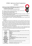
ETCR080D Large Caliber Clamp DC Current Sensor
User Manual
Thanks for your purchase of ETCR080D Large Caliber Clamp DC Current
Sensor of our company. For better use of the product, please make sure:
---to read this user manual in details.
---to abide by the safety regulations and precautions strictly.
u
u
u
u
Under any circumstance, it shall pay special attention on safety in use of this sensor.
Pay attention to words and symbols stick on the panel.
Keep the pliers clean, maintenance regularly.
Stop using the sensor when there is a rupture or break.
u Please don’t keep or store the sensor in the spot with high-temperature and moisture, or condensation,
and under direct daylight radiation for a long time.
u This sensor is only to be used, disassembled, and repaired by qualified personnel with authorization.
u When it may cause hazard by continuous use for the reason of the sensor itself, it shall immediately stop
using it and deposit it at once, leaving it for disposal by authorized agency.
u For risk of danger icon in manual
, users must perform safety operations strictly in compliance with the
manual content.
Ⅰ. Introduction
ETCR080D Large Caliber Clamp DC Current Sensor is used for measurement of high accuracy DC
current, leakage current. Adopt the latest CT technology and shielding technology. It is portable, clamp design,
no need to disconnect the measured circuits, non-contact, safe and fast, can be connected with industrial
control equipment, data recorder, oscilloscope, high precision digital multi-meter, etc. Widely applied in
electricity, communication, meteorology, railway, oilfield, construction, measurement, scientific and research
teaching unit, industrial and mining enterprises.
Ⅱ. Technical Specifications
Function
Measurement of DC current, leakage current
Test mode
Clamp CT
Power Supply
9V DC
Rated Power
2mW
Clamp Size
80mm×80mm
Range
0-10A DC
Resolution
10mA DC
±3.0%FS(50Hz/60Hz; 23℃±2℃, below 70%RH, keep the wire be in the
Accuracy
center of clamp)
Coils Turn
1: 800
Signal Output
2.5mV/10mA (0-10A/0-2.5V)
Red wire: positive power input; Yellow wire: ground; White wire: positive
Output Interface
signal output
Output Wire Length
2m
Measured Wire
Approximately in the geometric center of the clamp
Position
Line Voltage
Under 600VDC measurement
Dimension
194mm×145mm×40mm
Weight
780g
Working Environment -15℃-45℃; below 80%rh
Storage Environment -10℃-60℃; below 70%rh
Insulation Strength
AC3700V/rms (between core and shell)
Safety Rules
IEC1010-1, IEC1010-2-032, Pollution degree 2, CAT Ⅲ(600V)
-1-
Ⅲ. Principle and Structure
The sensor induced output a current I1, the current I1 generate voltage U on the external sampling load
resistance RL, so the measured current I can be calculated by measuring U. Output voltage 0-2.5V.
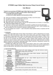
1. 1. Positive signal voltage output (white wire)
3. Positive power input (red wire)
5. Trigger (open and close the clamp)
7. Trigger (open and close the clamp)
2. Ground (yellow wire)
4. Output wire (2m)
6. Clamp
8. Power indicator
Clamp positive line or negative line separately to measure the DC current of
this line. (Note: single wire)
Clamp positive line and negative line together to measure leakage current of
this DC line. (Note: 2 wires)
Clamp earth wire of the DC system to measure the grounding line leakage
current. (Note: single wire)
Manufactured by
ETCR Electronic Technology Company
Address: F-3F, No.4 Pengshang Zhifu Road, Jiahe, Baiyun District, Guangzhou, Guangdong, China
Post Code: 510440
Tel: (86-20)62199556 62199553
Fax: (86-20)62199550
E-mail: [email protected]
Website: www.etcr.cc
-2-