1
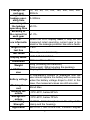
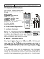
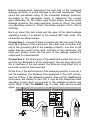
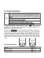
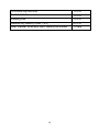
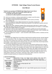
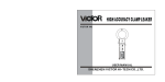
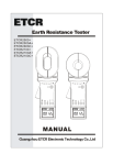
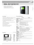
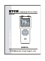
Content
Attention ...................................................................................................2
I. Brief introduction .................................................................................4
II. Electrical Symbol ...............................................................................4
III. Technical Specification .....................................................................4
IV. Instrument Structure .........................................................................6
V. Instrument Operation.........................................................................6
1. boot up, shutdown .........................................................................6
2. Manual / automatic switch ............................................................6
3. Switch the gear of rated operating current ....................................7
4. Reset..............................................................................................7
5. Measurement .................................................................................7
VI. Replacing Battery .............................................................................9
VII. Accessories ......................................................................................9
1
Attention
Thank you for purchasing ETCR8600 Leakage Protector Tester
of our company. In order to make better use of the product, please
be certain:
——To read this user manual carefully.
——To comply with the operating cautions presented in this
manual.
u Pay special attention to safety when using this instrument in any
case.
u Observe the text and symbols attached to the front and rear
panels of the instrument.
u Don not use the instrument to measure a line with a voltage
higher than 250V.
u Before measurement, disconnect the load fuse of the
measured leakage protector.
u L interface must connect to the fire wire, N interface must
connect to the ground wire.
u The Socket test line of the instrument is custom-made,
forbid to use other plug with cord instead of it.
u After measurement, removed the test wire from the measured
wire first.
u It is forbidden to use the instrument when neither rear cover of
the instrument nor the batter cover is in place.
u Never use the instrument when the instrument case or measuring wire is broken and therefore any metallic part is exposed.
u Don not place the instrument at a environment with high temperature, high humidity, condensation and direct sunshine for a
long time
u It is necessary to maintain the instrument periodically to keep it
clean. Don not wipe the instrument by using corrosive medium
or abrasive object.
u Please observe the correct polarity when replacing the battery.
Remove the battery from the instrument if you expect not to use
the instrument for a long time.
u Please replace the battery with a new one when the batter voltage is so low that the LCD display is dim.
2
u Operation, disassembly and maintenance of the instrument
must be carried out only by a authorized and qualified person.
u When there is an instrument fault, never use it because continual use may result in danger. In this case, isolate the instrument immediately and delivered to an authorized agency for
dealing with it.
u The user must follow the safety instructions preceded by
“ ”warning symbol on the instrument and manual.
u The user must strictly follow the instructions preceded by
“ ”danger symbol on the instrument and manual.
3
I. Brief introduction
ETCR8600 Leakage Protector Tester is well designed and manufactured for online measuring the leakage operating current,
leakage non-operating current, leakage operating time of the leakage protector; adopt 128dots×64dots displayed, it is convenient
and intuitive. The range of leakage current is 0~500mA(10 gears:
15, 30, 50, 75, 100, 150, 200, 250, 300, 500mA),range of the leakage operating time is 0~999ms. It is a product with high accuracy,
small size, light weight, exquisite appearance, easy to carry, is an
ideal tool for variety of leakage protector in site or in laboratory
testing.
II. Electrical Symbol
Extremely dangerous! The operators must keep to the
safety rules strictly, otherwise, electric shock will result in
death or injury.
Dangerous! The operators must keep to the safety rules
strictly, otherwise, electric shock will result in will result in
death or injury.
Warning! The operators must keep to the safety rules
strictly, otherwise, personal injury or equipment damage
will occur.
Double insulation.
Alternating current (AC).
Direct current (DC).
III. Technical Specification
Function
Power Supply
Test line Voltage
rated voltage
Measurement of leakage operating current,
leakage non-operating current, leakage operating time of the leakage protector.
DC6V alkaline batteries (LR6 1.5V×4).
Do not exceed AC 250V.
AC 220V.
4
Leakage current gear
range of the
leakage operating time
accuracy of
the leakage
operating time
accuracy of
the current for
each gear
Failure informatio
n
length of the
test line
Test mode
15, 30, 50, 75, 100, 150, 200, 250, 300,
500mA.
0~999ms.
±0.5%.
±1.0%.
When the LCD display fault, it may be the
measured rated operating current gear is too
small or the leakage protector has some faults.
1.8m.
Manually or automatically.
Display Mode
LCD: 128dots×64dots.
Dimension
170mm×75mm×30mm.
Weight
LCD Dimension
290g (including the batteries);
Total weight: 350g(including the packing).
Display field: 44mm×27mm.
A Low-Battery symbol is displayed and the
user should replace the battery with a new one
battery voltage
when the battery voltage drops to 4.8V. In this
case, the measured values are still accurate.
Working Cur40mA Max.
rent
Working Hu-10℃-40℃, below 80%rh.
miture
Storage Hu-10℃-60℃, below 70%rh.
miture
Insulating
≥100MΩ, AC2kV/rms(between the alloy of the
Strength
clamp and the housing).
Applicable
IEC1010-1, IEC1010-2-032, Pollution degree
5
safety rules
2, CAT III(600V) IEC61326(EMC standard).
IV. Instrument Structure
1. N interface (connect ground wire)
2. L interface (connect fire wire)
3. LCD
4. AT: auto key
5. RANGE+ key (gear up)
6. MT: manual key
7. RANGE- key(gear down)
8. RESET: reset key
9. POWER: (boot up, shutdown)
10. Crocodile clip test line
11. Probe test line
12. Socket test line
V. Instrument Operation
1. boot up, shutdown
Boot up the instrument by pressing the POWER key. The LCD will
light up. If the LCD display is dim, the battery voltage may be low. If
so, replace the battery with a new one. Press the POWER key
again to shutdown the instrument. This instrument will be shutdown automatically after starting 5 minutes.
2. Manual / automatic switch
This instrument has the manual (MT) and (AT) automatic test
mode. Press MT and AT key to switch to manual or automatic
mode. After boot up, it is default to the manual(MT) test mode. In
the manual mode, the top left corner of the LCD shows MT symbol,
in the automatic mode, the top left corner of the LCD shows MT
symbol.
In the automatic mode, start the measurement from the lowest
gear 15mA rated operating current. If the leakage protector does
not trip, the instrument will increase a gear automatically after 2
seconds. If the leakage protector also does not trip, the instrument
6
will increase a gear automatically again after 2 seconds, until the
trip breaking. At this time, the displayed gear on the button of LCD
screen is the actual leakage operating current value, the displayed
time is the leakage operating time.
3. Switch the gear of rated operating current
The rated operating current of the instrument from 0 to 500mA
were divided into ten gears: 15mA, 30mA, 50mA, 75mA, 100mA,
150mA, 200mA, 250mA, 300mA, 500mA. Press RANGE- or
RANGE+ to switch the gears. On the bottom of the LCD indicates
the current gear. After boot up, it is default to the lowest gear
(15mA) to start test.
4. Reset
After each test, press the RESET key to reset, the leakage operating time will be zero clearing, then can be tested again.
5. Measurement
Electric shock, dangerous! The instrument can be
operated only by the trained and authorized person.
The operators must keep to the safety rules strictly,
otherwise, electric shock will result in personal injury
or damage to the equipment.
Don not use the instrument to measure the lines with
a voltage of higher than 250V. Otherwise, electric
shock will result in personal injury or damage to the
equipment.
L interface must connect to the fire wire of the measured leakage protector, N interface must connect to
the ground wire of the measured leakage protector.
Otherwise, electric shock will result in damage to the
equipment.
The Socket test line of the instrument is custom-made, the red plug connect to the fire wire, the
black plug connect to the ground wire. Forbid to use
other plug with cord instead of it. Otherwise, electric
shock will result in personal injury or damage to the
equipment.
7
Before measurement, disconnect the load fuse of the measured
leakage protector to avoid damage to the load equipment. Then
check the nameplate rating of the measured leakage protector,
According to the nameplate rating to determine the current
gear.(Generally, for the indoor type single phase two-wire mode
leakage protector, the rated operating current is 30mA, the rated
non-operating current is 15mA, The break duration ≤0.1s, that is
≤100ms).
Boot up, select the test mode and the gear of the rated leakage
operating current, it is default to the manual (MT) test mode, The
connection as shown below:
Connection 1: one end of black crocodile clip test line insert to the
black N interface of the instrument, the other end (crocodile clip)
clip to the grounding pile of the leakage protector; one end of red
probe test line insert to the red L interface of the instrument, the
other end (probe) touch the fire wire of the leakage protector’s
output end to measurement.
Connection 2: the black plug of the dedicated socket test line insert into the N interface of the instrument, the red plug insert into
the L interface of the instrument, the three-pin plug insert into or
touch the socket to measurement.
At this time, if the performance of the leakage protector is normal, it
will trip breaking, the breaking time displayed in the LCD screen,
such as 075ms. If the leakage protector does not trip, fault failure
information will display in the LCD, it may be the measured rated
operating current gear is too small or the leakage protector has
some faults. Press the RESET key to reset, then can be tested
again.
8
VI. Replacing Battery
To avoid electric shock, when replacing the batteries, the test line must be pulled away from the instrument, and do not connect with the measured
wire.
Observe the correct battery polarity, otherwise, the
instrument will be damaged.
Replace the battery with a new one as soon as
possible when the battery voltage is low.
Do not mix the old and new battery together.
1. When the battery voltage drops to 4.8V, a
symbol will be
displayed on the instrument, indicating the battery voltage is low.
Replace the battery immediately.
2. Press the POWER key to shutdown the instrument. After confirming that the instrument has been shutdown f, open the battery
cover and replace with a new battery recommended by the manufacturer. Pay special attention to the correct battery polarity. Replace the battery cover, boot up the instrument and confirm that the
instrument can operate properly. (as shown in the following figures).
VII. Accessories
Tester
1 PCS
Shoulder bag
1 PCS
Probe test line
1 PCS
9
Crocodile clip test line
1 PCS
Socket test line
1 PCS
Packing box
1 PCS
Alkaline dry battery (AAA 1.5V)
4 PCS
User manual ,Warranty card ,Quality certificate
1 Copy
10
Manufactured by
ETCR Electronic Technology Company
Address: F-3F, No.4 Pengshang Zhifu Road, Jiahe, Baiyun
District, Guangzhou, Guangdong, China
Post Code: 510440
Tel: (86-20)62199556
Fax: (86-20)62199550
E-mail: [email protected]
Website: www.etcr.cc