1
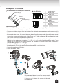
Waterproof Connector
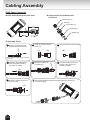
Components of the Waterproof Connector
Pin Definition
Screw Nut (A)
Seal (B)
Seals (C)
1 2 3 4 5 6 7 8
Housing (D)
Sealing Nut (E)
1
2
3
4
5
6
7
8
12V DC Output
Digital Output
Digital Input
Ground
AC 24V
AC 24V
RS485 +
RS485 -
1
2
3
4
Microphone In
Ground
Audio Out
Ground
1 2 3 4
Assembling Steps
1. Disassemble the components of the waterproof connector into part (A) ~ (E) as shown above.
2. Open the back cover of the Network Camera.
3. Remove the rubber stopper from the bottom of the Network Camera and secure the screw nut (A)
tightly.
4. If you need extra power for external devices, please feed the power cable through the wall mount
bracket and the waterproof connector (E --> D --> B --> A) as the illustration shows below. Then
connect the power cord to the socket. Note: There are 7 holes on the seal (B), and the widest hole
with a notch on the side is specific for power cord.
5. If you have external devices such as sensors and alarms, feed the cables through the wall mount
bracket and the waterproof connector (E --> D --> B --> A) as the illustration shown below. Then
refer to the pin definition to connect them to the general I/O terminal block. Note: The recommended cable gauge is 2.0 ~ 2.8 mm.
6. Push the seal (B) into the housing (D).
7. Insert the seals (C) into the empty holes on the seal (B) to avoid moisture.
8. Secure the sealing nut (E) tightly.
9. Clamp all cables, finally.
5
7
9
3
(B)
6
(A)
(C)
(D)
(B)
(D)
4
(E)
4
8
(E)
Note:
When using this waterproof connector, don't
use attached bracket to hook the camera to the
wall mount bracket. Since waterproof bracket
is big, you can't attach the camera to the wall
mount bracket.
13