1
UNDERSTANDING THE CODE
IIIT-D WSN Node having FLYPORT Module powered by Openpicus
(Thanks to Sneihil Gopal for preparing this document)
INTRODUCTION:
FLYPORT is a Ethernet / Wi-Fi module based on the open source platform openPICUS.
FLYPORT Wi-Fi is a compact module designed around the Microchip PIC 24FJ256GA106 processor (256K Flash,16K
Ram,16 Mips) and MRF24WB0MA/RM WI-FI Certified Transceiver.
FLYPORT is not simply a serial to Wi-Fi solution, but a smart module with no need of an external host processor as it
combines the processor power with the connectivity transceiver.
FLYPORT Ethernet is a wired LAN device embedding a Microchip PIC24FJ microcontroller and an Ethernet
transceiver. Plus the same 26 pin connector of Wi-Fi version, this module has a second 26 pin connector with the RJ45
signals and some I/Os.
A wide range of applications can be easily developed and run on FLYPORT with openPicus IDE. No Wi-Fi expertise is
needed. The IDE allows to focus on application as the openPicus framework handle the rest for you. It is based on
freeRTOS, manages the Wireless stack and its events.
FLYPORT provides the following services: Web server, TCP Socket, UDP Socket, SMTP Client, SNTP Client
GETTING STARTED :
Download and install the following free software to setup the complete environment to start your development on
FLYPORT modules:
C30 Microchip Compiler
Latest FLYPORT IDE
REFERENCE MANUALS :
Before moving on to Understanding the code, please download and read carefully the "FLYPORT Programmer's guide"
and "IDE User Manual":
FLYPORT programmer's guide The manual for FLYPORT functions
openPicus IDE 2.2 - User Manual The manual for openPicus IDE
To know about the IIIT-D WSN node please see Device Specifications.
ABOUT THE SENSORS :
The IIIT-D WSN node baseboard has three sensors:
Ambient Temperature Sensor DS18S20/DS18B20 :
The DS1820 Digital Thermometer provides 9–bit temperature readings which indicate the temperature of the
device. Information is sent to/from the DS1820 over a 1–Wire interface, so that only one wire (and ground) needs
to be connected from a central microprocessor to a DS1820. Power for reading, writing, and performing
temperature conversions can be derived from the data line itself with no need for an external power source.
Ambient Light Sensor APDS-9300
The APDS-9300 is a low-voltage Digital Ambient Light Photo Sensor that converts light intensity to digital signal
output capable of direct I2C interface. Each device consists of one broadband photodiode (visible plus infrared)
and one infrared photodiode. Two integrating ADCs convert the photodiode currents to a digital output that
represents the irradiance measured on each channel. This digital output can be input to a microprocessor where
illuminance (ambient light level) in lux is derived using an empirical formula to approximate the human-eye
response.
PIR Motion Sensor :
PIR sensors allow you to sense motion, almost always used to detect whether a human has moved in or out of the
sensors range. We use a digital PIR sensor which gives an output 1 if the motion is detected and 0 otherwise.
FIRMWARE ON IIIT-D WSN NODE :
The firmware on the IIIT-D WSN node is simple and easy to understand. It features an embedded Web Server that can be
modified and used for a number of purposes:
Sending parameters to the FLYPORT module at runtime.
Accessing the I/O ports at runtime.
Reading analog and digital sensor values in real time.
Connecting to a Wireless Network in infrastructure mode (allowing users to set SSID and access credentials
through their browser)
LOADING THE FIRMWARE :
The Firmware customized for IIIT-D WSN node can be check out at CODE FOR IIIT-D WSN NODE.
Install Tortoise SVN client to checkout latest code from http://iiitd-hostel
deployment.googlecode.com/svn/trunk
Correspondingly two folders named “Wi-Fi” (code folder for FLYPORT Wi-Fi) and “Eth” (code folder for
FLYPORT ETHERNET) will be checked out. You can check out the read-only version since you are not required
to commit back the code.
Now follow the steps mentioned at Load Firmware into IIIT-D WSN Node. (Note: Please skip the first two
steps as you have already checkout the code from the Google Code repository as described above).
FIRMWARE STRUCTURE:
As defined in the manual openPicus IDE 2.2 - User Manual The manual for openPicus IDE under the heading Project
Structure, the Firmware for IIIT-D WSN node has the following subfolders and files :
Project subfolders:
• Libs – contains the FLYPORT Framework libraries, the FreeRTOS files and the (optional) external libraries.
External Libs:
o
o
o
o
o
o
o
o
o
apds9300.c
clock.c
ds1820.c
generalfx.c
heap.s
pir.c
profile.c
rtcc.c
upload.c
FLYPORT Libs:
- for initialization of light sensor and determination of ambient light
- for initialization of RTCC based on SNTP
- for initialization of temperature sensor and determination of temp.
- for byte to decimal and decimal to byte conversions
- for correct compilation of the SNTP helper functions
- for initialization of PIR motion sensor and determination of motion
- for checking the network parameters to connect the FLYPORT
- for alarm time configuration
- for uploading the sensor data to the defined Server IP
o
o
o
o
o
o
o
o
o
o
ARPlib.c
FTP lib.c
HW lib.c
INT lib.c
ISRs.c
NET lib.c
Regs.c
SMTPlib.c
TCPlib.c
UDPlib.c
- provides the commands to manage ARP-IP association.
- provides Internet communication abilities
- Hardware library to manage the analog and digital IOs and UART
- Hardware library to manage the Interrupts
- for ISR (Interrupt Service routines)
- to manage Wifi and Ethernet modules and to change the network settings at runtime.
- for defining Registers
- to set the parameters for the SMTP connection, and to send emails from the FLYPORT
- contains all the command to manage the TCP sockets
- provides the commands to manage UDP connections
Free RTOS:
o
o
o
o
o
o
heap_2.c
- for memory management
list.c
- for list implementation used by the scheduler
port.c
- contains actual hardware-dependent code
portasm_PIC24.s – contains actual hardware-dependent code
queue.c
- handle FreeRTOS communication
tasks.c
- for creating, scheduling, and maintaining tasks.
•
Obj – contains the compiled files.
•
Web pages – contains the webpages of the webserver (optional). The webpages and all the related files
can be placed anywhere on the PC, but placing all the files inside this folder keep the complete project
easier to port, store and update.
•
Doc – contains the HTML documentation of the project. The first file that IDE will open should always be
named “index.html”.
Project files (in blue the files that can be edited by the user in the IDE):
• taskFLYPORT.c: the custom application source code (with related taskFLYPORT.h).
• HTTPApp.c: the code to manage the dynamic components of the webpages for the webserver
.
• WF_events.c: the file that manages all the WiFi events (and related WF_events.h). Those files are present
only in FLYPORT Wi-Fi projects.
• sensorwifi.conf / Ethernet.conf : it's the file used by the IDE to load the project and retrieve its information for
FLYPORT Wi-Fi and FLYPORT Ethernet respectively.
• HTTPPrint.h, HTTPPrint.idx, MPFSImg2.s (pic memory usage) or MPFSImg2.bin (external flash usage): these
files contain the webpages, the images (and all media) scripts, and all the information about dynamic variables of the
webserver. They are automatically generated during webpages import, user MUST NOT modify them manually.
• TCPIPConfig.h and WF_Config.h: the configuration files. These files are automatically modified by TCP wizard. User
should not modify them manually unless he doesn't know what he's doing. However, after manual changes (made outside
of the IDE), to take effect, a Recompile All command must be issued.
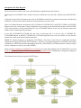
A schematic diagram of the flow of the firmware in IIIT-D WSN node is shown below:
FLOWCHART FOR UNDERSTANDING THE CODE:
Description of the Flow Diagram :
The first step in the execution of the code is the initialization of application specific hardware.
Following this, the FLYPORT Task is created. This task is dedicated to user code and is defined in the taskFLYPORT.c
file.
In this task, the basic Wi-Fi information, necessary for FLYPORT to know how to connect to the network is initialized by
ProfileInit ( ) function. This function checks the network parameters to connect with.
If the User Defined Network configuration (WF_CUSTOM for FLYPORT Wi-Fi and ETH_CUSTOM for FLYPORT
Ethernet) does exist, it means that a custom configuration was previously saved inside the flash memory of the FLYPORT
Wi-Fi microcontroller or in the External Memory in case of FLYPORT Ethernet. In this case, the firmware connects the
module to the customized network parameters.
In case WF_CUSTOM/ETH_CUSTOM does not exist it could mean that it is the first start of FLYPORT WiFi/FLYPORT Ethernet, or that WF_CUSTOM/ ETH_CUSTOM configuration was never saved. In this case, the firmware
connects the module to the default network parameters.
NOTE: The network parameters are changed by the HTTPApp.c file if the user provide a new configuration inside the
configuration webpage of FLYPORT Wi-Fi's/Ethernet’s web server. The function responsible of the handle of the update
of parameters is the HTTPExecutePost that changes all the WF_CUSTOM/ETH_CUSTOM parameters, and the saving of
the new configuration is done by the taskFLYPORT.c.
Please read Programming the FLYPORT-Core Concepts for a better understanding of the FLYPORT Web server and
Set WSN Node parameters for Node Server connection using P2P Client to understand the configuration webpage of
IIIT-D WSN node web server.
The schematic below shows the operation of HTTPApp.c :
The HTTPApp.c firstly provides for access protection to the FLYPORT Web page. In addition it supports for
both GET and POST requests made by the client and saves the customized network parameters.
NOTE: The SSID name, the Network Type ( Infrastructure or adhoc) and Security Configuration Parameters
(type and password) in the HTTPExecutePost are only for FLYPORT Wi-Fi projects.
After the customized Wi-Fi connection parameters are saved, the FLYPORT checks for Wi-Fi connection and displays a
message “FLYPORT connected… Hello World !!” for successful Wi-Fi connection and “Flyport ethernet connected to
the cable... hello world!” to indicate successful Ethernet connection on the UART.
Following a successful Wi-Fi connection, all the sensors on-board i.e. PIR motion sensor, Temperature sensor (DS18B20
/DS18S20) and the Light sensor (APDS 9300), connected to the FLYPORT are initialized in the same order.
The pir.c file in the external library of the Firmware consist of the PIRInit( ) for the initialization of the motion sensor.
The ds1820.c file in the external library has the DS1820Init( ) for the initialization of temperature sensor that is based
upon one-wire protocol.
The apds9300.c file in the external library of the Firmware consist of the APDSInit( ) for the initialization of the light
sensor and it also uses the I2C library.
Also initialization of RTCC based on SNTP and configuration of RTCC to raise an alarm every second is done in
ClockInit( ) that is in the External library file, clock.c.
In addition, a random delay using Random_Delay( ) is also added, which occur while initialization of the sensors.
If at the FLYPORT Web server page, client has enabled upload then the AppTask( ) function will also be executed. This
task is defined in the upload.c file include in the External library and enables the upload of sensor data into the server in
the form of JSON packets.
The function uses a variable alarmcount that is initially 0. At every initial value of alarmcount the timestamp
accompanying the data in the JSON packet is updated.
For alarmcount divisible by the Sampling Period i.e. by default 1 and leaving no remainder, another variable alarmread is
initialized to 1 and that commands the FLYPORT to read all the sensor’s data and store them in the respective arrays.
The DS1820Read( ), APDSRead( ) and PIRRead( ) functions are called to obtain temperature reading, light reading and
motion results respectively. All these functions are put in Critical Sections in order to avoid intermixing of sensor values.
This is done by using taskENTER_CRITICAL to enter the critical section and taskEXIT_CRITICAL to exit the same.
For alarmcount divisible by Publish Period i.e. by default 10 and leaving no remainder, the alarmupload is set to 1,
indicating that for each sensor the connection will now be established and data will be posted to the server port.
On alarmupload set to 1, the FLYPORT enters a loop to establish TCP connection and if connection is not established
even after maximum tries ( 10 in case of firmware for IIIT-D WSN node) a message “ Error Connecting to Server” is
displayed on the UART.
If the FLYPORT is able to establish a TCP connection before reaching the maximum number of tries, for each sensor the
Server Port at the defined Server IP is opened and a message “Connected to Server!!” is displayed on the UART.
After this the JSON packet for the respective sensor is made and pushed to the Server port. The port is then disconnected
and another message “ Disconnecting…” is displayed on the UART. The Server port is then closed and connection is
reestablished for the next sensor’s data.
On completion of data upload of all the three sensors i.e. PIR motion sensor, Temperature sensor and Light Sensor, the
message “END.” is displayed on the UART indicating successful posting of sensor data to the respective Server port of
the defined Server IP.
THE JSON PACKET :
What is JSON ??
JSON stands for JavaScript Object Notation
JSON is lightweight text-data interchange format
JSON is language independent *
JSON is "self-describing" and easy to understand
JSON is smaller than XML, and faster and easier to parse.
What is JSON object ??
The JSON object contains methods for parsing JSON and converting values to JSON. \
JSON object in the IIIT-D WSN node Firmware:
All the sensor data from the IIIT-D WSN node is uploaded to the Server Port of the defined Server IP in
the form of JSON packets. There is a predefined JSON format in which the data has to be sent.
The JSON object used in the IIIT-D WSN node Firmware is as shown below:
char *json_object[] = {
"{\"secretkey\":\"", profile.ApiKey,
"\",\"data\":",
"{\"loc\":\"", profile.Location,
"\",\"dname\":\"", profile.DeviceName,
"\",\"sname\":\"", sensorname,
"\",\"sid\":", sensorid,
",\"timestamp\":", timestamp,
",\"speriod\":", samplingperiod,
",\"channels\":",
"[{\"cname\":\"", channelname,
"\",\"unit\":\"", unit,
"\",\"readings\":[", sreadings,
"]}]}}\n"
};
An example of data received at the Server port for the three sensors viz. Motion, Light and Temperature, in the above
format is shown below:
{ "secretkey" : "45dc8ad8ecb7453a8989131d634637c8", "data" : { "loc" : "New Lab", "dname" : "dev20", "sname" :
"PIRSensor", "sid" : "1", "timestamp" : 1361698211, "channels" : [ { "cname" : "channel1", "unit" : "none",
"readings" : [ 0, 0, 0, 0, 0, 0, 0, 0, 0, 0 ] } ] } }
{ "secretkey" : "45dc8ad8ecb7453a8989131d634637c8", "data" : { "loc" : "New Lab", "dname" : "dev20", "sname" :
"LightSensor", "sid" : "1", "timestamp" : 1361698211, "channels" : [ { "cname" : "channel1", "unit" : "none",
"readings" : [ 8.9, 8.9, 8.9, 8.9, 8.9, 8.9, 8.9, 8.9, 8.9, 8.9, 8.9 ] } ] } }
{ "secretkey" : "45dc8ad8ecb7453a8989131d634637c8", "data" : { "loc" : "New Lab", "dname" : "dev20", "sname" :
"TemperatureSensor", "sid" : "1", "timestamp" : 1361698211, "channels" : [ { "cname" : "channel1", "unit" :
"celsius", "readings" : [ 23.3, 23.3, 23.3, 23.3, 23.4, 23.3, 23.3, 23.3, 23.3, 23.3 ] } ] } }
The data comprises of :
Secret Key or the API key that is given as input by the client at the configuration webpage of the FLYPORT web
server and saved by ProfileSave( ) in HTTPApp.c.
loc that is the location of the node given as input by the client at the configuration webpage of the FLYPORT web
server and saved by ProfileSave( ) in HTTPApp.c
dname is the device name given by the client to the node, at the webpage of FLYPORT webserver and saved by
ProfileSave( ) in HTTPApp.c
sname is the sensor name that is defined for each sensor in the switch case in makeJSON( ) in upload.c file and
executed in the PostTask( ) when TCP port is open.
sid is the sensor id that is defined in the upload.c file.
timestamp is obtained from the SNTP.
cname is the channel name defined in the upload.c file.
unit is the measuring unit of sensor data specified in the switch case in makeJSON( ) in upload.c file that is
Celsius for temperature and none for light and motion data.
readings are the sensor readings obtained by the DS1820read( ), APDSread( ) and PIRread( ) for the light,
temperature and motion data respectively in the AppTask( ) in upload.c file.
In case you wish to create your own JSON object, use the REST client available for different browsers to validate it.