1
Micriµm
Empowering Embedded Systems
µC/OS-II
µC/USB
µC/OS-View
for the
NXP LPC2888 CPU
(Using the Nohau LPC2800 Evaluation Board)
Application Note
AN-9888
www.Micrium.com
Micriµm
µC/OS-II, µC/OS-View and µC/USB for the
NXP LPC2888 CPU
Table Of Contents
1.00
1.01
1.02
Introduction
Directories and Files
IAR Embedded Workbench
2.00
2.01
2.02
Example Code
Example Code, app.c
Example Code, os_cfg.h
10
11
15
3.00
3.01
3.02
3.03
Board Support Package (BSP)
IAR-Specific BSP Files
BSP, bsp.c and bsp.h
LCD Display Control & Interface Functions
16
16
16
21
4.00
4.01
4.02
4.03
4.04
μC/USB
LPC2888 USB Considerations
LPC2888 μC/USB Driver Details
μC/USB-Bulk Example Enumeration
μC/USB-Bulk Example
25
25
27
35
36
5.00
µC/OS-View
37
3
4
8
Licensing
39
References
39
Contacts
39
2
Micriµm
µC/OS-II, µC/OS-View and µC/USB for the
NXP LPC2888 CPU
1.00
Introduction
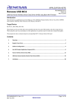
This document shows example code for using µC/OS-II, µC/OS-II and µC/USB on a Nohau
LPC2800 evaluation board, as shown in Figure 1, which employs NXP’s ARM7TDMI-based
LPC2888 microcontroller. This flexible, full-featured device includes interfaces for high-speed
USB 2.0, external SDRAM and Flash, MMC/SD memory cards, and various serial interfaces. In
addition to the processor’s internal memory—1 MB Flash, 64 kB SRAM, and 32 kB ROM—the
Nohau board is populated with one 128 Mb external SDRAM chip, one 64Mb external Flash chip
(with the capability for another to be inserted), and a MMC/SD memory card slot.
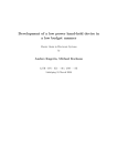
Uniquely, this processor may be powered from a single 1.5-volt AA battery, and though the
Nohau board includes a battery holder and jumpers to select this as the power supply, a more
usual source, a 5-volt DC adapter, was used as the power supply for all runs. The appropriate
jumper settings are shown in Figure 1-2 where the notation (
) superimposed on a jumper
location indicates that the two left pins will be connected. Note that the two left pins are not
necessarily pins 1 and 2, since pin 1 is designated as the pin beside the white triangle (.
).
LCD Display
MMC/SD Card
ADC1
USB Port
RS-232
Push button
switches
20-pin J-Tag
User LED
5V DC Power
Figure 1-1, Nohau LPC2800 board
3
Micriµm
µC/OS-II, µC/OS-View and µC/USB for the
NXP LPC2888 CPU
JP3: 2-3
JP4: 2-3
JP5: 2-3
JP20: 1-2
JP21: 2-3
JP22: 2-3
Figure 1.2, Jumper settings for 5V DC supply
1.01
Directories and Files
The code and documentation of the port are placed in directories in accordance with “AN-2002,
µC/OS-II Directory Structure”.
µC/OS-II:
\Micrium\Software\uCOS-II\Source
This directory contains the processor independent code for µC/OS-II. The version used
was 2.83.
\Micrium\Software\uCOS-II\Ports\ARM\Generic\IAR
This directory contains the standard processor-specific files for the generic µC/OS-II
ARM port assuming the IAR toolchain. These files could easily be modified to work with
other toolchains (i.e. compiler/assembler/linker/locator/debugger); however, you would
4
Micriµm
µC/OS-II, µC/OS-View and µC/USB for the
NXP LPC2888 CPU
place the modified files in a different directory. Specifically, this directory contains the
following files:
•
os_cpu.h
•
os_cpu_a.asm
•
os_cpu_c.c
•
os_dcc.c
•
os_dbg.c is included to provide additional information to Kernel Aware debuggers
like IAR’s C-Spy.
With this port, you can use µC/OS-II in either ARM or Thumb mode. Thumb mode,
which drastically reduces the size of the code, was used in this example, but compiler
settings may be switched to generate ARM-mode code without needing to change either
the port or the application code. The ARM/Thumb port is fully described in application
note AN-1014 which is available from the Micrium web site.
µC/OS-View:
\Micrium\Software\uCOSView\Source
This directory contains the processor independent code for µC/OS-View. The version
used was 1.20. This directory contains the following files:
•
os_view.c
•
os_view.h
\Micrium\Software\uCOSView\Ports\ARM7\LPC2888\IAR
This directory contains the LPC2888-specific port for µC/OS-View:
•
os_viewc.c
•
os_viewc.h
µC/USB:
\Micrium\Software\uC-USB-MSD\Firmware\USBBulk
This directory contains the source code for µC/USB-Bulk:
•
USB.h
•
USB_Main.c
•
USB_Private.h
•
USB_Read.c
•
USB_Setup.c
•
USB_Write.c
\Micrium\Software\uC-USB-MSD\Firmware\USBBulk
USB_X_uCOS-II.c, the µC/OS-II port for µC/USB-Bulk, is located in this directory.
5
Micriµm
µC/OS-II, µC/OS-View and µC/USB for the
NXP LPC2888 CPU
\Micrium\Software\uC-USB-Driver\LPC2888
The USB_hw.c file in this directory is the LPC2888-specific port for µC/USB-Bulk.
\Micrium\Software\EvalBoards\NXP\LPC2888\IAR\OS-View-USB
µC/USB-Bulk expects two configuration files:
•
USB_Descriptors.c provides definitions of the USB descriptors which will be
transmitted to the host during enumeration.
•
USB_Conf.h contains defines used to target the USB descriptors to the appropriate
driver or transmission protocol.
Application Code:
\Micrium\Software\EvalBoards\NXP\LPC2888\IAR\OS-View-USB
This directory contains the source code for the example application, composed of the
following files:
•
app.c contains the test code for the example application including the functions that
start µC/OS-II, register tasks with the operating system, and update the user
interface (the LEDs and LCD). The initialization functions of supplementary installed
modules, µC/OS-View and µC/USB, are called from this file as well. app_cfg.h
is a configuration file specifying stack sizes and priorities for all tasks and #defines
for important global application constants.
•
includes.h is a master include file used by the application.
•
os_cfg.h is the µC/OS-II configuration file.
•
LPC2888-OS-View-USB.* are the IAR Embedded Workbench project files.
\Micrium\Software\EvalBoards\NXP\LPC2888\IAR\BSP
This directory contains the Board Support Package for the Nohau LPC2800 board:
•
bsp.c contains the board support package which initializes critical processor
functions (e.g., the clock generation unit) and provides support for peripherals such
as the LCD display and the LED on the board. bsp.h contains prototypes for
functions that may be called by the user.
•
bsp_exceptions.c contains functions and variables for initializing interrupts,
installing handlers, and directing interrupts to the appropriate handlers. The
exception handler which will be called by the µC/OS-II ARM port when the OS
handles an interrupt is in this file.
•
LPC2888_RAM.xcl is an IAR linker file which contains information about the
placement of data and code segments in the processor’s memory map. The data,
code, and execution stacks are all mapped to RAM.
•
LPC2888_RAM.mac contains instructions that are executed prior to loading code
onto the processor. In this case, the processor is instructed to boot from RAM when
a warm reset occurs.
•
lpc2xxx_startup.s79
\Micrium\Software\uC-CPU\ARM\IAR
This directory contains processor-specific code intended to be used with the IAR
compiler for ARM processors.
6
Micriµm
µC/OS-II, µC/OS-View and µC/USB for the
NXP LPC2888 CPU
•
cpu_def.h, which is located directly in \Micrium\Software\uC-CPU, declares
#define constants for CPU alignment, endianness, and other generic declarations.
•
cpu.h defines the Micriµm portable data types for 8, 16, and 32-bit signed and
unsigned numbers (such as CPU_INT16U, which is a 16-bit unsigned type). These
allow code to be independent of processor and compiler word size definitions.
•
cpu_a.s contains generic assembly code for ARM7 or ARM9 processors which is
used to enable and disable interrupts within the operating system. This code is
called from C with OS_ENTER_CRITICAL() and OS_EXIT_CRITICAL().
\Micrium\Software\EvalBoards\NXP\LPC2888\Doc
This directory is the directory that contains the documentation for the Nohau LPC2800
board test code.
7
Micriµm
µC/OS-II, µC/OS-View and µC/USB for the
NXP LPC2888 CPU
1.02
IAR Embedded Workbench
We used the IAR Embedded Workbench (EW) V4.40a to test the example. Of course, µC/OS-II
can be used with other tools. Figure 1-3 shows the project configuration tree in the EW.
Figure 1-3, IAR EW Project Configuration
The test code works either in ARM or Thumb mode. In fact, if you switch between ARM and
Thumb Processor Mode in the settings dialog box (see Figure 1-4) and rebuild the project, your
code should run just as well. By selecting ‘Thumb’ and choosing to generate ‘Interwork’ code,
you can mix ARM and Thumb code in your application.
8
Micriµm
µC/OS-II, µC/OS-View and µC/USB for the
NXP LPC2888 CPU
Figure 1-4, IAR EWARM Options
The IAR Embedded Workbench works with Micrium’s µC/OS-II Kernel Awareness Plug-In which
allows you to examine µC/OS-II kernel objects in tabular format when running the IAR C-Spy
debugger.
Figure 1-5 shows all the tasks created in the example. For each task, you can see where the
current stack pointer is pointing, how much stack space is being used, and other properties. The
task names (which you may assign) are also listed.
The Kernel Awareness Plug-In provides a number of other useful information about µC/OS-II
(semaphore list, mailbox list, queue list, etc.).
Figure 1-5, µC/OS-II Kernel Awareness in C-Spy, Task List
9
Micriµm
µC/OS-II, µC/OS-View and µC/USB for the
NXP LPC2888 CPU
2.00
Example Code
When started, the example code displays on the LCD screen a summary of the current µC/OS-II
state (as shown in Figure 2-1). This summary includes the tick rate (i.e., number of ticks per
second), the CPU usage and clock speed, and two cumulative variables representing the total
number of ticks and the total number of context switches that have occurred since the application
was started.
Figure 2-1, μC/OS-II system information
Figure 2-2, Screen, Scrolled
The push buttons, which are polled 10 times per second, control the vertical “scrolling” of the
LCD. When push button #2 (labeled GPIO_3 on the board) is pushed, the text moves up and
wraps around to the bottom of the screen. Push button #1 has the opposite effect: when
pressed, the text moves down, toward the bottom of the screen, and wraps around to the top.
The information on the screen is refreshed five times per second.
10
Micriµm
µC/OS-II, µC/OS-View and µC/USB for the
NXP LPC2888 CPU
The left-hand potentiometer, immediately beneath the LCD—marked ADC1—can be used to
control the brightness of the display. If the knob is turned clockwise, then the display becomes
bright; when turned counterclockwise, the display dims. If the display is initially too dim or bright
to read, turn the knob to adjust the setting.
A simple demonstration of µC/USB-Bulk is provided as well. After initialization, this example
alternately reads from and writes to the USB port, incrementing the data byte between the read
and the write. The Nohau LPC2800 board resets when the USB cable is plugged in during
operation, moves through its boot sequence, and loads data from Flash. Because this overwrites
the code in RAM (whereto the data from the example project is written), the USB cable should be
inserted prior to programming the LPC2888.
2.01
Example Code, app.c
A limited set of the LPC2888 capabilities are exhibited by the application code in app.c. A few
tasks are created, one of which is dedicated to the user interface and update of the LCD.
Another, after initializing µC/USB-Bulk, alternately reads and writes from the USB port.
However, the power and convenience of both the µC/OS-II Kernel Awareness plug-in for C-Spy
and µC/OS-View are amply demonstrated with this small application.
As with most C programs, we assume that the compiler startup code brings the CPU to execute
main(). If you design an embedded application running out of Flash, we expect that you will
properly initialize the CPU (clocks, power management, memory management, chip selects, etc.)
and have your code call main().
Listing 2-1, main()
void
{
main (void)
CPU_INT08U
(1)
err;
BSP_IntDisAll();
(2)
OSInit();
(3)
OSTaskCreateExt(AppTask_Start,
(4)
(void *)0,
(OS_STK *)&AppTask_StartStk[APP_TASK_START_STK_SIZE - 1],
APP_TASK_START_PRIO,
APP_TASK_START_PRIO,
(OS_STK *)&AppTask_StartStk[0],
APP_TASK_START_STK_SIZE,
(void *)0,
OS_TASK_OPT_STK_CHK | OS_TASK_OPT_STK_CLR);
#if OS_TASK_NAME_SIZE > 13
OSTaskNameSet(APP_TASK_START_PRIO, "Start Task", &err);
#endif
OSStart();
(6)
}
L2-1(1)
(5)
As with most C applications, the code starts in main().
11
Micriµm
µC/OS-II, µC/OS-View and µC/USB for the
NXP LPC2888 CPU
L2-1(2)
All interrupts are disabled to make sure the application does not get interrupted until
it is fully initialized.
L2-1(3)
As with all µC/OS-II applications, OSInit() must be called before creating a task
or any other kernel object.
L2-1(4)
We then create at least one task (in this case, using OSTaskCreateExt() to obtain
additional information about your task). µC/OS-II creates either one or two internal
tasks in OSInit(). µC/OS-II always creates an idle task, OS_TaskIdle(), and
will create a statistics task, OS_TaskStat() if you set OS_TASK_STAT_EN to 1 in
OS_CFG.
L2-1(5)
As of V2.6x, you can now name µC/OS-II tasks (and other kernel objects) and
display task names at run-time or with a debugger. In this case, we name our first
task as well as the two internal µC/OS-II tasks. Because C-Spy can work with the
Kernel Awareness Plug-In available from Micrium, task names can be displayed
during debugging.
L2-1(6)
Finally, µC/OS-II is started by calling OSStart(). µC/OS-II will then begin
executing AppTask_Start() since that is the highest priority task created (both
OS_TaskStat() and OS_TaskIdle() have lower priorities).
Listing 2-2, AppStartTask()
static void AppStartTask (void *p_arg)
{
CPU_INT08U i;
CPU_INT08U j;
BOOLEAN
status1;
BOOLEAN
status2;
(void)p_arg;
BSP_Init();
(1)
#if OS_TASK_STAT_EN > 0
OSStatInit();
#endif
(2)
#if OS_VIEW_MODULE > 0
OSView_Init(38400);
OSView_TerminalRxSetCallback(AppTerminalRx);
OSView_RxIntEn();
#endif
#if uC_USB_BULK_MODULE > 0
AppInit_USB();
#endif
(3)
(4)
i = 0;
j = 0;
AppPrintPage();
adc_old = (ADC_GetStatus(1) >> 5) + 32;
while (DEF_TRUE) {
OSTimeDly(OS_TICKS_PER_SEC / 10);
j = (j + 1) % 2;
if (j == 0) {
AppUpdatePage();
}
(5)
(6)
(7)
status1 = PB_GetStatus(1);
12
Micriµm
µC/OS-II, µC/OS-View and µC/USB for the
NXP LPC2888 CPU
status2 = PB_GetStatus(2);
if ((status1 == DEF_TRUE) && (status2 == DEF_FALSE)) {
i = (i + 2) % 64;
LCD_SetStartLine(i);
LED_Toggle(1);
} else if ((status1 == DEF_FALSE) && status2 == DEF_TRUE) {
i = 63 - (65 - i) % 64;
LCD_SetStartLine(i);
LED_Toggle(1);
}
adc_new = (ADC_GetStatus(1) >> 5) + 32;
if (adc_new != adc_old) {
LCD_SetBrightness(adc_new);
adc_old = adc_new;
}
(8)
(9)
(10)
}
}
L2-2(1)
BSP_Init() initializes the Board Support Package—the I/Os, the tick interrupt, etc.
(See Section 3.0 for details.)
L2-2(2)
OSStatInit() is initializes µC/OS-II’s statistic task. This only occurs if you enable
the statistics task by setting OS_TASK_STAT_EN to 1 in OS_CFG.H. The statistics
task measures overall CPU usage (expressed as a percentage) and also performs
stack checking for all the tasks that have been created with OSTaskCreateExt()
with the stack checking option set.
L2-2(3)
OSView_Init() initializes the µC/ OS-View module, including the UART interface, for
which reason the baud rate of the RS-232C port connected to the Windows view is
specified as an argument. If you did not purchase µC/OS-View, please disable it
according to the instructions contained in Section 5.00.
L2-2(4)
AppInit_USB() creates a new task which will initialize the µC/USB-Bulk and
perform a simple test of the communications. See Listing 2-3.
L2-2(5)
The initial text is printed to the LCD. Also, in the next line, the initial brightness of the
display is set using the current value of ADC1, the left-hand variable resistor.
L2-2(6)
Any task managed by µC/OS-II must either enter an infinite loop ‘waiting’ for some
event to occur or terminate itself. In an infinite loop, the task polls the two user push
buttons, scrolling the screen if only one is pressed, and updates the LCD controller
RAM intermittently.
L2-2(7)
Five times per second the data in the LCD RAM is updated.
L2-2(8)
If push button #2 is pressed, then the text on the screen scrolls upwards, wrapping
around to the bottom of the screen.
L2-2(9)
If push button #1 is pressed, then the text on the screen scrolls downwards,
wrapping around to the top of the screen.
L2-2(10)
The current value of ADC1 is read and if this value is different than the old value, the
brightness of the LCD is changed accordingly. Due to the processing time necessary
for the A/D, the state of the display may lag behind the rotation of the ADC1 knob.
13
Micriµm
µC/OS-II, µC/OS-View and µC/USB for the
NXP LPC2888 CPU
Listing 2-3, AppTaskUSB()
static void AppTaskUSB(void *p_arg)
{
CPU_INT08U c;
(void)p_arg;
USB_Init();
USB_X_Init();
(1)
(2)
while (USB_IsConfigured() == 0) {
USB_X_Delay(150);
LED_Toggle(1);
}
(3)
LED_Toggle(1);
USB_X_Delay(500);
LED_Toggle(1);
USB_X_Delay(500);
LED_Toggle(1);
USB_X_Delay(500);
LED_Toggle(1);
USB_X_Delay(500);
(4)
while (DEF_TRUE) {
USB_Read(&c, 1);
(5)
LED_Toggle(1);
USB_X_Delay(50);
c++;
USB_Write(&c, 1);
}
}
This task is created by AppInit_USB(), called from AppStartTask(), to perform a simple test
of µC/USB-Bulk after initializing the stack and the LPC2888 USB controller. For further
information about the LPC2888 port, please refer to Section 4.00.
L2-3(1)
USB_Init() initializes the LPC2888 USB controller (see Section 4.00 for more
details).
L2-3(2)
USB_X_Init() initializes the structures, such as semaphores, provided by µC/OSII for µC/USB-Bulk.
L2-3(3)
While the USB configuration is incomplete, the task is delayed and a LED is toggled
between calls to USB_IsConfigured() to determine the current configuration
status.
L2-3(4)
The LED is toggled slowly four times to indicate that the USB controller is now
configured.
L2-3(5)
Within this infinite loop, a byte is read from the USB stack, incremented, and then
written back. Of course, this test will only work with a very specific application
running on the host, an example of which is provided directly under the Micriµm
directory in the zip file containing this document.
14
Micriµm
µC/OS-II, µC/OS-View and µC/USB for the
NXP LPC2888 CPU
2.02
Example Code, os_cfg.h
This file is used to configure µC/OS-II. Among the approximately 60 #defines in this file are
included variables defining the maximum number of tasks that your application can have, which
services will be enabled (semaphores, mailboxes, queues, etc.), and the size of the idle and
statistic task. Each entry is commented and additional information about the purpose of each
#define can be found in µC/OS-II, the Real-Time Kernel by Jean Labrosse. os_cfg.h
assumes you have µC/OS-II V2.83 or higher.
15
Micriµm
µC/OS-II, µC/OS-View and µC/USB for the
NXP LPC2888 CPU
3.00
Board Support Package (BSP)
The Board Support Package (BSP) provides functions to encapsulate common I/O access
functions and make porting your application code easier. Essentially, these files are the interface
between the application and the Nohau LCP2800 board. Though one file, bsp.c, contains some
functions which are intended to be called direcly by the user (all of which are prototyped in
bsp.h), the other files serve the compiler (as with lpc2xxx_cstartup.s79).
3.01
IAR-Specific BSP Files
The BSP includes three files intended specifically for use with IAR tools: LPC2888_RAM.xcl,
LPC2888_RAM.mac, and lpc2xxx_cstartup.s79. These serve to define the memory map
and initialize the processor prior to loading or executing code. If the example application is to be
used with other toolchains, the services provided by these files must be replicated as appropriate.
Before the processor memories can be programmed, the compiler must know where code and
data should be placed. To accomplish this, IAR requires a linker command file, such as
LPC2888_RAM.xcl, that provides directives to accomplish this. All code, data, and stack and
heap segments are placed in the 64kB internal RAM between 0x0000400040 and
0x0040FFFF. The first 64 bytes of RAM are reserved for the exception vector table.
The CSpy macro file LPC2888_RAM.mac declares routines which will be executed prior to
loading code on the processor and after a processor reset.
In lpc2xxx_cstartup.s79 is code which will be executed prior to calling main. One important
inclusion is the specification of the exception vector table (as required for ARM cores) and the
setup of various exception stacks. After executing, this function branches to the IAR-specific
?main function, in which the processor is further readied for entering application code.
3.02
BSP, bsp.c and bsp.h
We will not be discussing every aspect of the BSP but only cover topics that require special
attention.
bsp.c contains I/O control code as well as the code for handling the µC/OS-II tick interrupt.
Your application code needs to call BSP_Init() in order to properly initialize the services
provided by the file.
16
Micriµm
µC/OS-II, µC/OS-View and µC/USB for the
NXP LPC2888 CPU
Listing 3-1, BSP_Init()
void
{
BSP_Init (void)
BSP_Cache_Init();
BSP_CGU_Init();
BSP_Int_Init();
Tmr_TickInit();
(1)
(2)
(3)
(4)
LCD_Init();
LCD_ClrScr();
(5)
PB_Init();
}
L3-1(1)
This function maps the bottom portion of RAM—where the exception vectors are
located by specification within the linker command file—to 0x00000000, where ARMs
expect the exception vectors to be located. See Listing 3-2 for details.
L3-1(2)
The clock generation unit and the clocks used for peripheral chip functions are
initialized. See Listing 3-3 for details.
L3-1(3)
We then call a function which is responsible for initializing the Interrupt Controller.
See Listing 3-4 for details.
L3-1(4)
The µC/OS-II tick interrupt source is then initialized. See Listing 3-5 for details.
L3-1(5)
The LCD on the evaluation board is then initialized. See Listing 3-6 for details.
Listing 3-2, BSP_Cache_Init()
static void BSP_Cache_Init (void)
{
CACHE_SETTINGS = 0x00000001;
CACHE_SETTINGS = 0x00000000;
(1)
(2)
while ((CACHE_RST_STAT) & 0x00000001) {
;
}
(3)
CACHE_PAGE_CTRL = 0x00000001;
ADDRESS_PAGE_0 = (0x400000 >> 21);
CACHE_SETTINGS = 0x00000016;
(4)
(5)
(6)
}
L3-2(1)
The cache controller is reset.
L3-2(2)
The reset bit is de-asserted.
L3-2(3)
CACHE_RST_STAT is polled to determine whether the cache reset process, which
takes 128 clock cycles, has completed.
L3-2(4)
Caching is enabled for page 0, which covers the range between 0x00000000 and
0x001FFFFF.
L3-2(5)
The address range covered by page 0, 0x00000000 to 0x001FFFFF, will become the
virtual address range for the the 2 kB following 0x400000, which is the lower part of
RAM in the LPC2888. Thus, if the address location 0x0000001C is accessed, the
address 0x0040001C will be loaded.
17
Micriµm
µC/OS-II, µC/OS-View and µC/USB for the
NXP LPC2888 CPU
L3-2(6)
Caching is enabled for both data and instructions.
Listing 3-3, BSP_CGU_Init()
static void
{
LPPDN
LPFIN
LPMSEL
LPPSEL
LPPDN
BSP_CGU_Init (void)
=
=
=
=
=
0x00000001;
0x00000001;
0x00000003;
0x00000001;
0x00000000;
(1)
(2)
(3)
(4)
(5)
while (LPLOCK == 0x00000000) {
;
}
(6)
SYSFSR1
SYSSCR
APB0FSR1
APB0SCR
APB1FSR1
APB1SCR
UARTFSR1
UARTSCR
(7)
=
=
=
=
=
=
=
=
CGU_FSR_MAIN_PLL;
CGU_SCR_ENF1;
CGU_FSR_MAIN_PLL;
CGU_SCR_ENF1;
CGU_FSR_MAIN_PLL;
CGU_SCR_ENF1;
CGU_FSR_MAIN_PLL;
CGU_SCR_ENF1;
SYSFDCR1 &= ~CGU_FDCR_FDRUN;
(8)
SYSFDCR1
(9)
= ((BSP_SYSFSR2_MSUB << 11)
| (BSP_SYSFSR2_MADD << 3)
|
CGU_FDCR_FDSTRCH
|
CGU_FDCR_FDRES);
SYSFDCR1 &= ~CGU_FDCR_FDRES;
(10)
SYSFDCR1 |= CGU_FDCR_FDRUN;
(11)
AHB0ESR
USBESR0
LCDESR1
LCDESR0
=
=
=
=
CGU_ESR_SSCLOCK;
CGU_ESR_SSCLOCK;
CGU_ESR_FD1;
CGU_ESR_SSCLOCK;
(12)
T0ESR
T1ESR
= CGU_ESR_SSCLOCK;
= CGU_ESR_SSCLOCK;
(13)
UARTESR1
= CGU_ESR_SSCLOCK;
(14)
SYSBCR
= CGU_BCR_FDRUN;
(15)
}
L3-3(1)
The main PLL is powered down.
L3-3(2)
The main oscillator (12 MHz) is selected as the PLL’s input clock.
L3-3(3)
The output clock from the PLL will be CPLL = (LPMSEL + 1) x COSC = 48 MHz
L3-3(4)
The CCO frequency, which should be between 160 MHz and 320 MHz, is
CCO = COSC x 2LPPSEL + 1 = 48 MHz x 4 = 192 MHz.
L3-3(5)
The main PLL is powered up.
L3-3(6)
LPLOCK is polled until it holds a non-zero value, which indicates that the PLL has
locked.
L3-3(7)
The clocks are routed to devices via a hierarchical scheme. These four lines assign
the PLL output to four selection stages: the main system stage, the APB0 stage, the
18
Micriµm
µC/OS-II, µC/OS-View and µC/USB for the
NXP LPC2888 CPU
APB1 stage, and the UART stage. Later, in L3-3(12), the spreading stages will
distribute these (and clocks from the fractional dividers) to the various clocks used on
the processor.
L3-3(8)
The SYS selection stage’s fractional divider number 1 is stopped.
L3-3(9)
The SYS selection stage’s fractional divider number 1 is setup.
fractional divider is equal to
The output of the
C PLL × n C PLL × − M SUB
=
so M ADD = m − n , M SUB = − n
m
M ADD − M SUB
The output of the clock, which will be the LCD clock, should be equal to 6 MHz;
therefore, n = 16 = 0 x10 and m = 128 = 0 x80 is a solution. The proper values of
M ADD and M SUB will be 0x70 and 0x10 , respectively.
L3-3(10)
The reset bit of the SYS selection stage’s fractional divider number 1 is toggled off.
L3-3(11)
The SYS selection stage’s fractional divider number 1 is restarted.
L3-3(12)
The SYS selection stage clock is chosen as clock for the USB and LCD PCLK
selection stages. However, the output of SYS’s fractional divider number 1 is chosen
as the LCD bus clock.
L3-3(13)
The APB1 selection stage clock is chosen as the clock for the timer selection stages.
L3-3(14)
The UART selection stage clock is chosen asthe clock for the UART selection stage.
Listing 3-4, BSP_Int_Init()
static void BSP_Int_Init (void)
{
CGU_INT16U i;
for (i = 1; i < 29; i++) {
Int_Table[i] = (CGU_INT32U)BSP_Dummy_ISR_Handler;
}
(1)
}
L3-4(1)
The variable, Int_Table, is an array declared in bsp.c to hold the addresses of the
ISR handlers. The LPC2888 does not have registers to hold these values. Instead,
the LPC2888 expects these to be stored in memory and provides a register,
INT_VECTOR0, that may be loaded with the base address of a table in memory for
such a purpose. We chose an alternative approach, merely instantiating an array
and, in this function, initializing each ISR address to that of a dummy routine. As you
install other interrupts for your application, some of these locations will be replaced
by your own interrupt handlers.
19
Micriµm
µC/OS-II, µC/OS-View and µC/USB for the
NXP LPC2888 CPU
Listing 3-5, Tmr_TickInit()
static void Tmr_TickInit (void)
{
CGU_INT32U
clk_freq;
INT_REQ5
= ((1 << 27)
| (1 << 26)
| (1 << 16)
| (1 << 28)
|
0x1);
Int_Table[5]
/*
/*
/*
/*
/*
Target is stored in bit 8
Enable is stored in bit 16
Enable the interrupt
Value in 3:0 indicates the priority
Set priority to 1
= (CPU_INT32U)Tmr_TickISR_Handler;
*/
*/
*/
*/
*/
(1)
(2)
clk_freq = BSP_CPU_ClkFreq();
Tmr_ReloadCnts = (clk_freq * 1000) / OS_TICKS_PER_SEC ;
(3)
T0CTRL
T0LOAD
T0CTRL
(4)
(5)
= 0;
= Tmr_ReloadCnts;
= 0xC0;
}
L3-5(1)
The timer interrupt is enabled, a priority (which could be used by an IRQ handler) is
established, and the interrupt is set to trigger an IRQ rather than a FIQ.
L3-5(2)
The tick ISR handler location is stored in the Int_Table array (see Listing 3-3 for
more information).
L3-5(3)
The timer reload value is calculated.
L3-5(4)
The LPC2888 timers are count-down timers that trigger an interrupt when reaching
zero and, optionally, can be loaded with the value specified in the T0LOAD register.
L3-5(5)
The timer is configured to reload with the value in T0LOAD and is enabled.
Listing 3-6, LCD_Init()
static void
{
LCDCTRL
LCD_Init (void)
= 0x4000;
(1)
LCD_WrCmd(LCD_RESET_DISPLAY
);
LCD_WrCmd(LCD_BIAS_SET_1_9
);
LCD_WrCmd(LCD_ADC_SELECT_REVERSE
);
LCD_WrCmd(LCD_COMMON_OUTPUT_NORMAL );
LCD_WrCmd(LCD_V5_RESISTOR_RATIO
);
LCD_WrCmd(LCD_ELECTRONIC_VOLUME_SET );
LCD_WrCmd(LCD_ELECTRONIC_VOLUME_INIT);
LCD_WrCmd(LCD_POWER_CONTROL_SET |
LCD_VOLTAGE_REGULATOR |
LCD_VOLTAGE_FOLLOWER |
LCD_BOOSTER_CIRCUIT
);
LCD_WrCmd(LCD_DISPLAY_REVERSE
);
LCD_WrCmd(LCD_DISPLAY_ON
);
(2)
}
L3-6(1)
The LCD chip select pin, LCS, is programmed to be low-active.
L3-6(2)
A series of commands are transmitted to the LCD controller specifying the hardware
setup. After calling LCD_Init(), strings and characters can be written to the
display using the functions LCD_DispStr() and LCD_DispChar(). These
interface functions are described in section 3.1.
20
Micriµm
µC/OS-II, µC/OS-View and µC/USB for the
NXP LPC2888 CPU
3.03
LCD Display Control & Interface Functions
The LCD display used on the Nohau LPC2800 evaluation board is controlled with an Epson
S1D15605-series LCD driver. Unlike the Hitachi HD44780-compatible character-driven drivers
supported by µC/LCD, the Epson driver is pixel-driven and must be sent not a character’s ASCII
representation, but its dot-matrix representation. The BSP contains functions that define a
character-driven programming interface for the module; however, a more extensive set of display
functions, allowing individual pixels to be toggled or lines to be drawn, could be implemented.
The LPC2888 includes an LCD interface compatible with 8-bit data buses such as the Intel 8080
or the Motorola 6800. By using this interface, control lines between the LCD and the processor
are automatically set or cleared, and data or commands written to the appropriate register are
automatically placed into a FIFO and routed to the data bus.. That the Epson S1D115605 is
compatible with this interface greatly simplifies the code.
The Epson S1D115605 contains on-board RAM sufficient for storing the pixel data for the 65
pixel rows by 132 pixel columns of the screen. A write to the controller modifies not the LCD
output (which, of course, will change when updated) but the information in the RAM. This level of
abstraction allows for additional flexibility, in several ways:
1) The “start line” is modifiable. The row of data displayed topmost on the screen may
be set between 0 and 63, a functionality which may be accessed using
LCD_SetStartLine() (see Listing 3-11). When performed dynamically, a “scrolling” effect
may be achieved, as is demonstrated in the LPC2888 sample application, with almost no
processor usage and little programming effort.
2) The display may be reversed. Without rewriting data to the S1D115605 RAM, the
lit/unlit status of all LCD pixels may be reversed by writing a certain command to the
display.
3) Read/modify/write cycles are possible. The RAM may be read and a modified version
written back. If a specific set of sequential columns in a page need to be accessed and
changed repeatedly—as for a blinking cursor or character, for example—the load on the
S1D115605’s processing unit may be decreased with a special command sequence.
After an initial command to enter read/modify/write mode, only writes will cause the
accessed column to increment. When this mode is no longer required, an end command
is sent to the controller, and the column position is restored to the location when the
mode was entered.
The character-driven user interface is comprised of four functions:
LCD_DispChar()
LCD_DispStr()
LCD_DispClrLine()
LCD_ClrScr()
The first two functions store characters and strings, respectively, at specified locations
Epson controller’s RAM. The last two allow the entire contents and a single line
controller’s RAM, respectively, to be cleared (meaning, to be set all pixels
LCD_DispChar() is presented in Listing 3-7, and LCD_DispClrLine() is presented
3-8.
on the
of the
“off”).
Listing
Additionally, three functions are called by the interface functions to perform lower-level actions:
21
Micriµm
µC/OS-II, µC/OS-View and µC/USB for the
NXP LPC2888 CPU
LCD_WrCmd()
LCD_WrData()
LCD_SetBrightness()
LCD_SetPosition()
The first two functions LCD_WrCmd() and LCD_WrData(), write a command or a byte of data to
the driver (see Listing 3-10). The third function, LCD_SetBrightness(), sets the brightness of
the display to one of the 64 possible levels, as specified by its argument. The forth function,
LCD_SetPosition(), sets the position of the RAM to which data will be written (see Listing 39).
Listing 3-6, LCD_DispChar()
void
{
LCD_DispChar (CPU_INT08U line, CPU_INT08U col, CPU_INT08U c)
CPU_INT08U
i;
if (col < BSP_LCD_CHARACTERS_PER_LINE &&
line < BSP_LCD_NUMBER_OF_LINES) {
LCD_SetPosition(line, col);
for (i = 0; i < 8; i++) {
LCD_WrData(BSP_LCD_Charset[c-32][i]);
}
(1)
(2)
(3)
}
}
L3-7(1)
The validity of the function arguments, col and line, is checked.
L3-7(2)
The display position is set (see Listing 3-8).
L3-7(3)
A “font” is defined in bsp.c as the double-subscripted array BSP_LCD_Charset.
Each row in the array specifies a certain character, and each character is itself a list
of eight unsigned eight-bit integers specifying the eight columns in the character’s
dot-matrix representation (as shown in Figure 3-1 for ASCII character 0x40, “@”).
The integer 32 is subtracted from the c, the ASCII character code, because the first
row of the table defines character 0x20 (or 32 in decimal), the space. (See Listing 39 for a description of LCD_WrData()).
22
Micriµm
µC/OS-II, µC/OS-View and µC/USB for the
NXP LPC2888 CPU
Program Reference
BSP_LCD_Charset[64][0]
BSP_LCD_Charset[64][1]
BSP_LCD_Charset[64][2]
BSP_LCD_Charset[64][3]
BSP_LCD_Charset[64][4]
BSP_LCD_Charset[64][5]
BSP_LCD_Charset[64][6]
BSP_LCD_Charset[64][7]
Hexadecimal
Binary
{0x00,
0x00,
0x00,
0x32,
0x49,
0x79,
0x41,
0x3E}
00000000
00000000
00000000
00110010
01001001
01111001
01000001
00111110
Character Output
Figure 3-1. Coding of ASCII Character 0x40, “@”
Listing 3-8, LCD_DispClrLine()
void
{
LCD_DispClrLine (CPU_INT08U line)
CPU_INT08U c_pos;
CPU_INT08U i;
if (line < BSP_LCD_NUMBER_OF_LINES) {
LCD_SetPosition(line, 0);
for (c_pos = 0; c_pos < BSP_LCD_CHARACTERS_PER_LINE; c_pos++) {
for (i = 0; i < 8; i++) {
LCD_WrData(BSP_LCD_Charset[0][i]);
}
}
}
(1)
(2)
(3)
}
L3-8(1)
The validity of the function argument, line, is checked.
L3-8(2)
The display position is set (see Listing 3-8).
L3-8(3)
A space character is written to the position occupied by each of the characters in the
line.
LCD_ClrScr() loops through each line of the display, and for each line performs the same
operation LCD_DispClrLine() performs for its argument—writing space characters to each
character position.
Listing 3-9, LCD_SetPosition()
static void LCD_SetPosition (CPU_INT08U line, CPU_INT08U col)
{
CPU_INT08U nibble_upper;
CPU_INT08U nibble_lower;
nibble_upper = (col & 0x1E) >> 1;
nibble_lower = (col & 0x01) << 3;
(1)
LCD_WrCmd(LCD_PAGE_ADDRESS_SET + line
); (2)
23
Micriµm
µC/OS-II, µC/OS-View and µC/USB for the
NXP LPC2888 CPU
LCD_WrCmd(LCD_COLUMN_ADDRESS_UPPER_BIT_SET | nibble_upper); (3)
LCD_WrCmd(LCD_COLUMN_ADDRESS_LOWER_BIT_SET | nibble_lower);
}
L3-9(1)
The col argument passed to LCD_SetPosition is the character column on the
display; however, the actual pixel column must be passed to the LCD driver. The
pixel column is eight times the character column (there being eight columns of pixels
in each character), and the upper and lower halves of the value must be passed in
separate commands. This line and the next shift col left by three bits and extract
the upper four and lower four bits, respectively.
L3-9(2)
The LCD driver sets the “start line”, or the line in the LCD controller’s RAM which will
be the top line on the LCD display.
L3-9(3)
The desired page address of the display is sent to the driver. The RAM of the driver
is divided into eight pages, each of which is eight pixels high; conveniently, this is the
height of the font we defined. The page address coincides, consequently, with the
line number.
L3-9(4)
The upper and lower halves of the pixel column are passed to the LCD driver.
Listing 3-10, LCD_WrData()
static void LCD_WrData (INT8U data)
{
CPU_INT32U status;
status = (LCDSTAT >> 5) & 0x1F;
while (status >= 0x0E) {
status = (LCDSTAT >> 5) & 0x1F;
}
(1)
(2)
LCDDBYTE = data;
(3)
}
L3-10(1)
The number of bytes currently in the output FIFO is extracted from the LCDSTAT
register value.
L3-10(2)
The function waits until the number of bytes in the output FIFO (which can hold only
16 bytes) no longer exceeds 13.
L3-10(3)
The data passed to the function is placed into the LCDDBYTE register. The function
LCD_WrCmd(), which is used to write commands to the display, differs only by
writing its argument to the byte instruction register, LCDIBYTE.
Listing 3-11, LCD_SetStartLine()
void
{
LCD_SetStartLine(CPU_INT08U line)
LCD_WrCmd(LCD_START_LINE_SET + (line & 0x3F));
(1)
}
L3-11(1)
The LCD driver sets the “start line”, or the line of data in the LCD controller’s RAM
which will be the top line on the LCD display.
24
Micriµm
µC/OS-II, µC/OS-View and µC/USB for the
NXP LPC2888 CPU
4.00
μC/USB
USB (Universal Serial Bus) is a communications bus allowing the transfer of information between
one host and connected peripheral devices. The Nohau LPC2800 board includes a USB port
which is connected to the LPC2888 USB module. This module supports the high-speed USB
interface, whereby data transfer speeds of 480 Mb/s may be attained, but is backward compatible
with the full-speed and low-speed modes.
To take advantage of this hardware, μC/USB-Bulk, a USB bulk protocol stack, has been ported
to this board. μC/USB-Bulk utilizes bulk transfers, one of the three data transfer methods
between a host and its peripheral (the other two are isochronous and interrupt transfers). The
simplicity and speed of the bulk transfer protocol enables the stack to be easily ported, while
providing a logical transfer method for bursty or intermittent communications, as might be
expected on a mass storage device.
μC/USB-Bulk is independent of both hardware and the operating system, so two ports, one for
each of the hardware and OS, must be provided. The LPC2888-specific driver implemented (as
all hardware drivers must) the following functions:
4.01
Initialization function:
• USB_HW_Init()
Buffer control functions:
• USB_HW_BufferAvailable()
• USB_HW_FreeBuffer()
Input/output functions:
• USB_HW_Read()
• USB_HW_SendData()
Controller setup functions:
• USB_HW_Attach()
• USB_HW_UnloadEP0()
• USB_HW_StallEP0()
• USB_HW_SetAddress()
• USB_HW_EnableEp1()
• USB_HW_EP0_Send()
• USB_HW_ClearOutPacketReady()
• USB_HW_ClrSetupEnd()
Interrupt functions:
• USB_HW_DisableRxInterrupt()
• USB_HW_EnableRxInterrupt()
Other functions:
• USB_HW_memcpy()
• USB_HW_ForceConfiguredState()
LPC2888 USB Considerations
The most current NXP user manual for the LPC2888, Rev. 01 dating from September 5, 2006,
provides helpful information regarding the USB registers and covers the basic elements of the
general USB controller. The more fundamental function considerations regarding setup of the
endpoints and receipt of packets is more thoroughly covered in the documentation of NXP’s
25
Micriµm
µC/OS-II, µC/OS-View and µC/USB for the
NXP LPC2888 CPU
ISP1582/3 USB controller. The ISP1582/3 has essentially the same interface as the LPC2888
USB controller and, more importantly, the operation of the two devices may be judged (nearly)
identical given that the guidelines of the ISP1582/3 provided the necessary details for writing a
driver for the LPC2888. The following documents were consulted for the port:
the ISP1582 “Product Data” guide (revision 04);
the ISP1582 firmware programming guide, AN10046 (revision 03); and
the ISP1582 FAQs, NA 10046 (revision 05).
Where one of these documents provides justification for a particular coding decision, as covered
in the code listings below, citations will be given.
The LCP2888 includes 8 physical endpoints (EP0 through EP7) and 16 logical endpoints (IN and
OUT endpoints for each of EP0 through EP7). The host perspective is always considered when
terming an endpoint “IN” or “OUT”, implying that an IN endpoint sends data to the host and an
OUT endpoint receives data from the host. Four logical endpoints are used, two for the control
transfers (EP0 IN and EP0 OUT) and two for the bulk transfers (EP1 IN and EP2 OUT), but, from
a programming viewpoint, five endpoints are effectively considered. These are the four logical
endpoints plus an EP0 SETUP endpoint to which the EP0 setup packets are routed. Each of
these five has its own FIFO (accessed by the USBData register) and setup and control registers
(USBEType, USBECtrl, USBMaxSize, and USBDCnt). The particular set of endpoint registers
(such as that corresponding to EP1 IN) is selected by writing to the USBEIX (USB Index) register
prior to any attempted access.
USB control transfers are used during device enumeration, the process by which the host learns
the peripheral’s capabilities and sets up the peripheral prior to the transfer of actual data. Each
transfer involves three phases:
1) Setup phase. In this phase, the host informs the peripheral as to the type of transfer to
expect (i.e., whether data will be sent to the host or received from the host) and the data
which will be transferred.
2) Data phase. Data may be transferred from the peripheral to the host or from the host to
the peripheral. Control transfers which require no transfer of data lack this phase.
3) Status phase.
transfer.
In this phase, the peripheral indicates the result of the data phase
Interrupts will be received for the EP0 SETUP endpoint only when when the peripheral receives
the setup packet during the setup phase, and the EP0 SETUP endpoint registers and FIFO will
be used only when reading this packet (see Listing 4-3). The EP0 IN endpoint registers and
FIFO are used during the data phase of a control transfer when the peripheral will send packets
to the host (a data IN stage; see Listing 4-4). Similarly, the EP0 OUT endpoint registers and
FIFO are used during the data phase when the the host will send additional packets to the
peripheral (a data OUT stage; this type of transfer is not used in this driver). Interrupts are
received on the EP0 IN and EP0 OUT in response to ACKs (acknowledgements) from the host.
An IN ACK interrupt is received after the completion of the data phase on a control transfer with a
data IN stage; an OUT ACK interrupt initiates the reading of data from the EP0 OUT FIFO during
the data OUT stage of a control transfer.
26
Micriµm
µC/OS-II, µC/OS-View and µC/USB for the
NXP LPC2888 CPU
4.02
LPC2888 μC/USB Driver Details
The application must call the functions USB_Init() and USB_X_Init() before commencing
USB transfer. USB_Init() calls two functions from the hardware driver, USB_HW_Init() and
USB_Attach(). After the former, the USB controller should be prepared to receive a bus reset
interrupt. The latter should enable a pull-up on the DP pin, be it through the setting of an I/O pin
or some functionality internal to the controller, causing the host to detect the presence of the
device. The programmatic flow following this call is interrupt-driven, proceeding through
enumeration, until the device is brought into a configured state. Figure 4-1 presents a basic
flowchart of the USB control flow; portions of this diagram will be enlarged upon in later sections.
Note that while the two steps are initiated by the device (or its user), the last three are controlled
by the host.
Initialize
USB controller
USB_HW_Init()
USB_X_Init()
Attach to host
USB_HW_Attach()
Be enumerated
by host
(See Figure 4-2)
Transfer data
USB_Read()
USB_Write()
Figure 4-1. Basic steps of using a USB connection:
Flow (left); Function calls (right)
Listing 4-1, USB_HW_Init()
void
{
USB_HW_Init (void)
USBCLKEN
= USBCLKEN_CLKEN;
USBMODE
USBMODE
|= USBMODE_SOFTRESET;
&= ~USBMODE_SOFTRESET;
USBMODE
|= USBMODE_CLKAON;
(1)
(2)
USBDEVADR
= 0x00000000;
(3)
USBINTCFG
= 0x00000054;
(4)
USBINTCLR = USBINT_ALL;
USBEINTCLR = USBEINT_ALL;
USBINTE
= USBINT_BRESET;
27
Micriµm
µC/OS-II, µC/OS-View and µC/USB for the
NXP LPC2888 CPU
USB_IntInit();
(5)
USBMODE
(6)
|= USBMODE_GIE;
}
L4-1(1)
The USB controller clock is not enabled immediately after reset (contrary to what is
written in the LPC2888 documentation).
L4-1(2)
A soft reset is performed.
L4-1(3)
The device address is set to the default value, zero.
L4-1(4)
The interrupts are configured preparatory for a bus reset. First, the policy for
interrupt generation and the polarity and parity of the interrupt signal are set using
the USBINTCFG register. Second, all interrupts are cleared by writing the
USBINTCLR and USBEINTCLR registers. Third, the bus reset interrupts is enabled.
L4-1(5)
The USB_IntInit() function, defined in bsp.c, is called to initialize the USB vectors
within the LPC2888 interrupt controller and assign USB_ISR_Handler() as the
interrupt handler.
L4-1(6)
Interrupts within the USB controller are enabled.
Once the LPC2888 USB controller has been initialized and the pull-up on the DP pin has been
enabled (using the SoftConnect feature), the host procedes with enumeration. Figure 4-2
presents the flow through this phase. Listing 4-2 presents the code for USB_ISR_Handler(),
which receives all USB interrupts and routes each interrupt to the proper handler.
28
Micriµm
µC/OS-II, µC/OS-View and µC/USB for the
NXP LPC2888 CPU
Receive bus reset
interrupt; configure
controller to receive EP0
setup packets
USB_ISR_Reset()
Receive EP0
interrupt; read
setup packet
Data IN
phase?
USB_ISR_EP0_
Setup()
NO
YES
Move to data
phase
Move to
status
phase
Transfer data
Receive
IN ACK
interrupt;
move to
status phase
Receive
EP0 OUT
interrupt
NO
USB_HW_ClearOut
PacketReady()
USB_HW_UnloadEP0()
USB_ISR_EP0_Send()
Receive
IN ACK
interrupt
USB_ISR_EP0_IN()
USB_ISR_EP0_OUT()
Configured?
YES
Setup bulk
endpoints
USB_HW_EP1_
Enable()
Figure 4-1. Enumeration process:
Flow (left); Function calls (right)
29
USB_ISR_EP0_IN()
Micriµm
µC/OS-II, µC/OS-View and µC/USB for the
NXP LPC2888 CPU
Listing 4-2, USB_ISR_Handler()
void
{
USB_ISR_Handler (void)
USB_U32
USB_U32
USB_U32
USB_U32
USB_U32
int_status;
int_enable;
inte_status;
inte_enable;
pkt_size;
int_status
int_enable
inte_status
inte_enable
=
=
=
=
USBINTSTAT;
USBINTE;
USBEINTSTAT;
USBEINTE;
int_status &= int_enable;
inte_status &= inte_enable;
(1)
if (int_status & USBINT_EP0STAT) {
USB_ISR_EP0_Setup();
USBINTCLR
= USBINT_EP0STAT;
}
if (int_status & USBINT_BRESET) {
USB_ISR_Reset();
USBINTCLR
= USBINT_BRESET;
}
if (int_status & USBINT_SUSP) {
if (int_status & USBINT_RESUME) {
USBINTCLR = USBINT_SUSP | USBINT_RESUME;
} else {
USB_ISR_Suspend();
USBINTCLR = USBINT_SUSP;
}
} else if (int_status & USBINT_RESUME) {
USB_ISR_Resume();
USBINTCLR
= USBINT_RESUME;
}
(2)
if (inte_status & USBEINT_EP0_OUT) {
USB_ISR_EP0_OUT();
USBEINTCLR = USBEINT_EP0_OUT;
}
if (inte_status & USBEINT_EP0_IN) {
USB_ISR_EP0_IN();
USBEINTCLR = USBEINT_EP0_IN;
}
if (inte_status & USBEINT_EP1_IN) {
USB__OnTx();
USBEINTCLR = USBEINT_EP1_IN;
}
if (inte_status & USBEINT_EP2_OUT) {
USBEIX
= USBEIX_EP2_OUT;
pkt_size
= (USB_U32)USBDCNT;
USB__OnRx(pkt_size);
USBEINTCLR = USBEINT_EP2_OUT;
}
(5)
(3)
(4)
(6)
(7)
(8)
}
L4-2(1)
The currently triggered interrupts are ANDed with the currently enabled interrupts to
prevent any unenabled interrupts from being handled. The structure of the handler
function allows all enabled, triggered interrupts to be handled (assuming code has
been placed in the function for a particular interrupt).
L4-2(2)
The interrupt generated by the receipt of an EP0 setup packet is handled (by the call
to USB_ISR_EP0_Setup()) and then cleared. See Listings 4-4 and 4-5.
L4-2(3)
The interrupt generated by a bus reset is handled (by the call to USB_ISR_Reset())
and then cleared. See Listing 4-3.
30
Micriµm
µC/OS-II, µC/OS-View and µC/USB for the
NXP LPC2888 CPU
L4-2(4)
Suspend and resume from suspend interrupts are handled in the body of this if
structure and its connected else. As directed in the answer to question 2.4 in the
ISP1582 FAQ document (AN 10046), when both a suspend and resume interrupt
occur, neither is handled, but both are cleared. Otherwise, the received suspend or
resume from suspend interrupt is handled and cleared.
L4-2(5)
The EP0 OUT endpoint interrupt is handled and cleared. This interrupt is only
received following the movement to the status stage of a control transfer with a data
IN stage; however, according to the ISP1582 firmware programming guide (AN
10039), no interrupt should be generated in this circumstance.
L4-2(6)
The EP0 IN endpoint interrupt is handled and cleared. This interrupt is received
following the completion of the data stage of a control transfer with a data IN stage,
or following the movement to the status stage of a control transfer with no data stage.
According to the ISP1582 firmware programming guide (AN 10039), no interrupt
should be received in the latter circumstance.
L4-2(7)
The interrupt generated when the host wants to receive data is handled and cleared.
L4-2(8)
The interrupt generated when the host wants to transmit data is handled (after the
number of bytes to receive has been read from USBDCNT) and cleared.
Listing 4-3, USB_ISR_Reset()
static void USB_ISR_Reset (void)
{
USBDEVADR = USBDEVADR_DEVEN;
USBINTCFG = 0x00000054;
(1)
(2)
USBEIX
USBETYPE
= USBEIX_EP0;
= USBETYPE_ENABLE | USBETYPE_CTRL;
USBEIX
USBETYPE
= USBEIX_EP0_IN;
= USBETYPE_ENABLE | USBETYPE_CTRL;
USBEIX
USBETYPE
= USBEIX_EP0_OUT;
= USBETYPE_ENABLE | USBETYPE_CTRL;
USBINTE
= USBINT_BRESET | USBINT_EP0STAT
| USBINT_SUSP
| USBINT_RESUME;
= USBEINT_EP0_IN | USBEINT_EP0_OUT;
USBEINTE
(3)
(4)
}
L4-3(1)
The LPC2888’s USB controller is enabled at the default address (zero).
L4-3(2)
The policy for interrupt generation set.
L4-3(3)
The EP0 setup, EP0 IN, and EP0 OUT endpoints are enabled as control endpoints.
The maximum packet size will be set for the bulk endpoints, but, according to
question 2.5 in the ISP1582 FAQs (AN 10046), doing so for the control endpoints
could result in errors.
L4-3(4)
The interrupts and endpoint interrupts necessary for proceeding through enumeration
of the device are enabled.
31
Micriµm
µC/OS-II, µC/OS-View and µC/USB for the
NXP LPC2888 CPU
Listing 4-4, USB_HW_EP0_Setup()
static void USB_ISR_EP0_Setup (void)
{
USB_U32
rx_word;
USB_SETUP_PACKET pkt;
USB_U32
rx_size;
USBEIX
rx_size
= USBEIX_EP0;
= USBDCNT;
if (rx_size >= 8) {
rx_word
pkt.bmRequestType
pkt.bRequest
pkt.wValueLow
pkt.wValueHigh
=
=
=
=
=
USBDATA;
(USB_U8)( rx_word
&
(USB_U8)((rx_word >> 8) &
(USB_U8)((rx_word >> 16) &
(USB_U8)((rx_word >> 24) &
0x000000FF);
0x000000FF);
0x000000FF);
0x000000FF);
=
=
=
=
=
USBDATA;
(USB_U8)( rx_word
&
(USB_U8)((rx_word >> 8) &
(USB_U8)((rx_word >> 16) &
(USB_U8)((rx_word >> 24) &
0x000000FF);
0x000000FF);
0x000000FF);
0x000000FF);
rx_word
pkt.wIndexLow
pkt.wIndexHigh
pkt.wLengthLow
pkt.wLengthHigh
(1)
(2)
USB__HandleSetup(&pkt);
(3)
}
}
L4-4(1)
The EP0 setup endpoint is selected.
L4-4(2)
Though the verification is unnecessary, the packet size, which should be eight bytes,
is checked. The eight bytes are retrieved from the FIFO via the EP0 setup endpoint’s
USBDATA registered and stored in the packet passed to the function.
L4-4(3)
The µC/USB-Bulk function USB__HandleSetup() is called to determine the
nature of the setup packet and request the appropriate action. There are three
possible situations:
1)
2)
3)
The request involves a data IN stage.
In this case,
USB_HW_ClearOutPacketReady() will be called to move the transfer to
the data stage, and USB_HW_EP0_Send() will be called to transfer the data
(see Listing 4-5).
The
request
involves
no
data
stage.
In
this
case,
USB_HW_Unload_EP0() is called to moving the transfer directly to the
status stage (see Listing 4-5(4)).
The request is either unknown or unhandled. EP0 is stalled in this
situation.
A fourth possibility, a control request with a data OUT stage, is not encountered
during enumeration and, consequently, will not be handled by this document.
32
Micriµm
µC/OS-II, µC/OS-View and µC/USB for the
NXP LPC2888 CPU
Listing 4-5, USB_HW_EP0_Send()
void
USB_HW_EP0_Send (const unsigned char *p_data,
unsigned char nbytes,
char tx_null_pkt)
{
USB_U32
USB_U8
tx_word;
*p;
USBEIX = USBEIX_EP0_IN;
USBDCNT = nbytes;
(1)
p = (USB_U8 *)p_data;
if (nbytes != 0) {
if (nbytes >= 4)
do {
tx_word
tx_word
tx_word
tx_word
USBDATA
{
(2)
=
|=
|=
|=
*(p
*(p
*(p
*(p
+
+
+
+
0);
1) << 8;
2) << 16;
3) << 24;
= tx_word;
p
+= 4;
nbytes
-= 4;
} while (nbytes >= 4);
}
if (nbytes--) {
tx_word = *p++;
if (nbytes--) {
tx_word |= *p++ << 8;
if (nbytes--) {
tx_word |= *p++ << 16;
}
}
USBDATA = tx_word;
}
} else {
USBDCNT
= 0;
USBECTRL
= USBECTRL_STATUS;
}
(3)
(4)
}
L4-5(1)
The EP0 IN endpoint is selected, and the number of bytes to send is written to its
USBDCNT register.
L4-5(2)
The full four-byte words are written to the EP0 IN endpoint’s USBDATA register, one
by one.
L4-5(3)
If the total number of bytes to send was not a multiple of four, the final word of data is
assembled and written to the USBDCNT register.
L4-5(4)
If no bytes were to be sent, then the control transfer is moved to the status phase. In
this case, USB_HW_EP0_Send() will have proceeded identically to
USB_HW_Unload_EP0(), which moves a control transfer with no data phase to the
status phase.
33
Micriµm
µC/OS-II, µC/OS-View and µC/USB for the
NXP LPC2888 CPU
Listing 4-6, USB_HW_EnableEP1()
void
{
USB_HW_EnableEP1 (void)
USBEIX
USBETYPE
USBEIX
USBETYPE
USBEIX
USBETYPE
USBEIX
USBETYPE
=
=
=
=
=
=
=
=
USBEIX_EP1_IN;
0x00000000;
USBEIX_EP1_OUT;
0x00000000;
USBEIX_EP2_IN;
0x00000000;
USBEIX_EP2_OUT;
0x00000000;
(1)
USBEIX
USBMAXSIZE
USBEIX
USBMAXSIZE
USBEIX
USBMAXSIZE
USBEIX
USBMAXSIZE
=
=
=
=
=
=
=
=
USBEIX_EP1_IN;
0x00000040;
USBEIX_EP1_OUT;
0x00000040;
USBEIX_EP2_IN;
0x00000040;
USBEIX_EP2_OUT;
0x00000040;
(2)
USBEIX
USBETYPE
=
=
|
=
=
|
=
=
|
=
=
|
USBEIX_EP1_IN;
USBETYPE_BULK
USBETYPE_ENABLE;
USBEIX_EP1_OUT;
USBETYPE_BULK
USBETYPE_ENABLE;
USBEIX_EP2_IN;
USBETYPE_BULK
USBETYPE_ENABLE;
USBEIX_EP2_OUT;
USBETYPE_BULK
USBETYPE_ENABLE;
(3)
|= USBEINT_EP1_IN
| USBEINT_EP2_OUT;
(4)
USBEIX
USBETYPE
USBEIX
USBETYPE
USBEIX
USBETYPE
USBEINTE
}
L4-6(1)
The answer to ISP1582 FAQ 2.15 (AN 100046) provides clear directions for the
initialization of endpoints, which, when done improperly, may cause data corruption.
In the first step, all endpoints which will be used should be disabled. (The ISP1582
firmware programming guide provides one additional instruction: both the IN and the
OUT endpoint should be initialized for any logical endpoint number for which either
the IN or OUT endpoint is used. Consequently, the EP2 IN and EP1 OUT endpoints,
which are unused in this driver, are initialized by this function.)
L4-6(2)
The maximum packet size is set to 64 for each endpoint.
L4-6(3)
The endpoint type for each endpoint is selected, and the endpoints are enabled.
L4-6(4)
The interrupts for the endpoints which will be used are enabled.
34
Micriµm
µC/OS-II, µC/OS-View and µC/USB for the
NXP LPC2888 CPU
4.03
μC/USB-Bulk Example Enumeration
The sequence of interrupts during enumeration depends on the host and the device driver.
Figure 4-3 presents an example enumeration sequence which culminated in successful reads
and writes to the LPC2888 from a personal computer running Windows XP. As mentioned in the
previous sections, interrupts are received unexpectedly in two situations:
1) An EP0 IN interrupt is received following the movement to the status phase of a control
transfer with no data phase.
2) An EP0 OUT interrupt is received following the movement to the status phase of a control
transfer with a data IN phase.
Int. #
0
1
2
3
4
5
6
7
8
9
10
11*
14*
17*
20*
23*
26*
29*
32*
35*
38*
41
42
43
44
45
Setup Packet
Meaning
Request
Request Value
Index
Length
Type
0
0
0
0
0
Bus reset
0
0x80
0x06
0x0100 0x0000 0x0040 Get device descr.
EP0 setup
0
0
0
0
0
EP0 IN
0
0
0
0
0
0
EP0 OUT
0
0
0
0
0
0
Susp./Res.
0
0
0
0
0
0
Bus reset
0
0x00
0x05
0x0003 0x0000 0x0000 Set address
EP0 setup
0
0
0
0
0
EP0 IN
0
0x80
0x06
0x0100 0x0000 0x0012 Get device descr
EP0 setup
0
0
0
0
0
EP0 IN
0
0
0
0
0
0
EP0 OUT
0
0x80
0x06
0x0200 0x0000 0x0009 Get config. descr
EP0 setup
0x80
0x06
0x0300 0x0000 0x00FF Get language ID
EP0 setup
0x80
0x06
0x0303 0x0409 0x00FF Get serial num.
EP0 setup
0x80
0x06
0x0200 0x0000 0x00FF Get config. descr
EP0 setup
0x80
0x06
0x0300 0x0000 0x00FF Get language ID
EP0 setup
0x80
0x06
0x0302 0x0409 0x00FF Get product ID
EP0 setup
0x80
0x06
0x0300 0x0000 0x00FF Get language ID
EP0 setup
0x80
0x06
0x0302 0x0409 0x00FF Get product ID
EP0 setup
0x80
0x06
0x0100 0x0000 0x0012 Get device descr
EP0 setup
0x80
0x06
0x0200 0x0000 0x0009 Get config. descr
EP0 setup
0x80
0x06
0x0200 0x0000 0x0020 Get config. descr
EP0 setup
0
0
0
0
0
EP0 IN
0
0
0
0
0
0
EP0 OUT
0
0x00
0x09
0x0001 0x0000 0x0000 Set configuration
EP0 setup
0
0
0
0
0
EP0 IN
0
Interrupt
Figure 4-3. Example enumeration sequence.
* Each of these interrupts, like interrupts numbers 8 and 40, is
followed by an EP0 IN and an EP0 OUT interrupt.
35
Micriµm
µC/OS-II, µC/OS-View and µC/USB for the
NXP LPC2888 CPU
4.04
μC/USB-Bulk Example
µC/USB-Bulk includes a sample application which performs a simple test of the bulk
communication on the device. This application, which is located in
\Micrium\Software\uC-USB-Bulk\SampleApp
continuously alternates between writes to and reads from the device. The application expects
that the value it reads will be one greater than the value it previously wrote. Once Windows has
enumerated the device, run the application (by clicking on the executable, for instance). If the
device is properly connected (and continues to be connected), no message boxes should appear;
the output in the terminal window should merely indicate the input and output transfers as such
occur (as shown in Figure 4-4). However, if the application fails to connect to the device or if the
data read is otherwise than the expected value, a message box (like in Figure 4-5) should appear
with a warning. When this message box is closed, the application will exit.
Figure 4-4. Example Output from SampleApp
Figure 4-5. Message Box Indicating Error in SampleApp
36
Micriµm
µC/OS-II, µC/OS-View and µC/USB for the
NXP LPC2888 CPU
5.00
µC/OS-View
The application code described in this application note allows you to connect a Windows-based
PC to your target and display run-time information about your target in a Window as shown in
Figure 5-1. This is done via an add-on module called µC/OS-View.
Figure 5-1, µC/OS-View Windows’ ‘Viewer’
Note that you can ‘disable’ µC/OS-View by removing the µC/OS-View files from the build and
setting OS_VIEW_MODULE to 0 in os_cfg.h. You would need to do this is you didn’t purchase
µC/OS-View from Micriµm.
µC/OS-View is a combination of a Microsoft Windows application program and code that
resides in your target system (in this case, the LPC2888 Evaluation Board). The Windows
application connects to your system via an RS-232C serial port. The status of the tasks which
are managed by µC/OS-II can be viewed with the Windows application.
µC/OS-View allows you to view the following information from a µC/OS-II based product:
• The address of the TCB of each task (up to 63 tasks);
• The name of each task (up to 63 tasks);
• The status (e.g., ready, delayed, waiting on event) of each task;
• The number of ticks remaining for a timeout or if a task is delayed;
37
Micriµm
µC/OS-II, µC/OS-View and µC/USB for the
NXP LPC2888 CPU
• The amount of stack space used and left for each task;
• The percentage of CPU time each task relative to all the tasks;
• The number of times each task has been 'switched-in'; and
• The execution profile of each task.
µC/OS-View also allows you to send commands to your target and allow your target to reply
back and display information in a 'terminal window'.
µC/OS-View is licensed on a per-developer basis. In other words, you are allowed to install
µC/OS-View on multiple PCs as long as the PC is used by the same developer. If multiple
developers are using µC/OS-View then each needs to obtain his own copy. Contact Micriµm
for pricing information.
38
Micriµm
µC/OS-II, µC/OS-View and µC/USB for the
NXP LPC2888 CPU
Licensing
μC/OS-II is provided in source form for FREE evaluation, for educational use or for peaceful
research. If you plan on using μC/OS-II in a commercial product you need to contact Micriμm to
properly license its use in your product. We provide ALL the source code with this application
note for your convenience and to help you experience μC/OS-II. The fact that the source is
provided does NOT mean that you can use it without paying a licensing fee. Please help us
continue to provide the Embedded community with the finest software available. Your honesty is
greatly appreciated.
References
µC/OS-II, The Real-Time Kernel, 2nd Edition
Jean J. Labrosse
R&D Technical Books, 2002
ISBN 1-57820-103-9
Embedded Systems Building Blocks
Jean J. Labrosse
R&D Technical Books, 2000
ISBN 0-87930-604-1
Contacts
IAR Systems
Century Plaza
1065 E. Hillsdale Blvd
Foster City, CA 94404
USA
+1 650 287 4250
+1 650 287 4253 (FAX)
e-mail: [email protected]
WEB : www.IAR.com
CMP Books, Inc.
1601 W. 23rd St., Suite 200
Lawrence, KS 66046-9950
USA
+1 785 841 1631
+1 785 841 2624 (FAX)
e-mail: [email protected]
WEB: http://www.cmpbooks.com
Micriµm
949 Crestview Circle
Weston, FL 33327
USA
+1 954 217 2036
+1 954 217 2037 (FAX)
e-mail: [email protected]
WEB: www.Micrium.com
NXP
1110 Ringwood Court
San Jose, CA 95131
USA
+1 408 474 8142
WEB: www.nxp.com
39