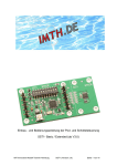
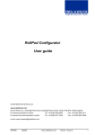
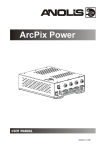
1
Installation guide and users-manual of the Pod- and Schottelsteering
SST1
IMT Innovative Modell Technik Hamburg
SST1 (Version 1.3)
Page 1 / 14
Thank you very much for choosing our Pod- and Schottelsteering SST1.
Please read the entire user’s manual carefully prior installing and using the device.
This user’s manual contains important safety instructions, detailed information about fitting,
parameterization and operation of the SST1 steering.
You will recognize even the steps are complicate in reading will work out pretty simple as we have
concentrated on practicality during engineering.
If you face any additional question about the initial installation, the parameterization or the operation
please view our videos at www.imth.de or contact us.
This user’s manual is part of the product. Please keep it safely and in case of forwarding the product to
a third party, please make sure the user´s manual goes with it.
Any non-observance of this user manual or the safety regulations will result in void of warranty.
Continuous improvement is driving our work. Therefore scope of delivery in form, function, design and
technical ability might be subject of change.
Please be aware that no claims can be derived out of any pictures, given information, descriptions and
drawings.
Delivery contents:
1 x user manual
1 x PCB SST1
1 x disc Magnet
Safety:
The SST1 PCB is designed to operate in models of ships and is only allowed to be used in that way.
Use this device only within the given specification (see table of specification).
Store and use the SST1 steering only in a dry environment.
Any mechanical- or electrical change to the steering or exceed of the specification will result in
immediate loss of any warranty against the manufacturer.
Any damage to the guarantee seal on the bottom result in immediate loss of warranty also.
Pay special attention of running in “Master-Slave” mode is more unsafe. You should only operate this
mode in a safe environment. More details are under “Master-Slave Mode” at page 11 of this manual.
Check the correct operation and function of the steering out of the water prior any ride.
Specification:
Voltage:
Operating Power:
Max. Power:
Impulse In:
Impulse Out:
Weight:
Size (BxTxH):
Operating Temperature:
Demanding Channels:
5,5 - 10,0 V
ca. 30 mA at 6,0 V
1,0 A
< 5,5 V
ca. 5,0 V
ca. 15g
80 x 40 x 12 mm
o
0 - 40 C
2
IMT Innovative Modell Technik Hamburg
SST1 (Version 1.3)
Page 2 / 14
Introduction:
Different ways of steering are common in navigation. Also one is named Pod-propulsion and offered
by different manufacturers.
All of them have one thing common: The Pods are able to run a full circle with no limit in turn.
As the direction to move the propeller keeps always the same, you only achieve a change of direction
by turning the propeller half a circle.
The benefits of such engines are not only the ability in exact maneuvering.
The available Servos and remote controls are not able to provide such realistic steering, because the
Servos are limited with no endless turn.
You overcome this boundary with your SST1 steering first time. Maneuvering your model ship
absolutely as real is now possible with standard model components.
After fitting the SST1 and accompanying mechanical and electrical adjustments, you need to align the
SST1 to your remote control and pod. This parameterization only need to be done once, as all settings
will be saved. The settings are available to upload at next restart.
Basic requirements to use the SST1:
To enable your ship for realistic steering with the SST1 your model needs to provide following two
basic properties:
1.) Your pods can show a 360° electrical turn without the given turn limit.
You have two options to achieve this requirement:
•
A speed control directs an engine in both directions. This engine is linked to a gear and
achieves an alternative turn of the pod.
•
You choose a Servo and remove the turn limitation. Doing so you achieve a single unit
including speed control, engine and gear in one housing.
The recommended 2nd option, to simply remove the turn limitation and keep using the professionally
built combination of speed control, engine and gear is shown in an example video on www.imth.de.
2.) The actual position of the pod needs to be recorded by a sensor, which is directly on the SST1
board.
The sensor uses a magnet to record the position of the pod without touching it. The magnet moves
analog to the pod above the sensor.
If the pod carries a full circle the magnet needs to do the same!
Right now it is uncritical if the direction of both turns are synchronic or opposite. Important is the
analogy of the two turns to provide a 1:1 balance of magnet to pod.
IMT Innovative Modell Technik Hamburg
SST1 (Version 1.3)
Page 3 / 14
Mechanical Installation:
As you already read the revolving magnet needs to be installed above the sensor.
The sensor is located in the middle of the SST1 in the smaller part of the pcb, which is separated from
the main part by the dotted line.
The magnet needs to be installed centered above the sensor with a distance of 0.5 to 1.5mm.
For your easier installation we have provided 4 holes around the sensor. The sensor is installed in the
center of these 4 holes. For further easy identification you will find a cross on the backside of the pcb,
which also identifies the center.
As better you place the magnet as more accurate the sensor will recognize the angle of the pod and
more exact you can run it.
If the SST1 dimensions are too big, you might separate the sensor part from the main pcb at this
dotted line and reconnect the two parts with 5 wires.
Connection 1 to connection 1 and so force of the row X3 and X4. The connection shouldn´t be longer
than 10 cm.
Attention: You will lose the warranty carrying out this action.
Of course we will service you if needed also in this case.
IMT Innovative Modell Technik Hamburg
SST1 (Version 1.3)
Page 4 / 14
Electrical Installation:
For a safe use the pcb needs unshielded DC of 5.5 – 10.0 Volts, which have to be connected to the
headers X1 and X2
Pay attention that all (+) connections within the SST1 are connected with each other as well as all
(-) connections.
With a DC of 5.5 to 10.0 Volts you should be able to connect the servo and the speed control to the
header X2 directly only if the power carries less than 1.0 Ampere. Pay attention to the max operating
Power.
In the case the DC is higher 6.0 V, normally most servos are not capable. In this case you have to
disconnect the (+) to the servo or the speed control and reconnect to a suitable power support.
On the pulse inputs it is allowed to have max 5V only.
This will normally be the case if you have a direct connection from the receiver to the SST1.
You can run the SST1 with 5V also. To do so, you have to place a solder bridge und cut a small trace.
Attention: Following the modification some safety precautions will be overridden and you will lose the
warranty.
Best if you use a BEC module providing 5.5 V to run the steering in this case. In any case the
operating power exceeds 5.5 V the steering will be destroyed.
If you still want to modify, cut the existing bridge at J1 between 2 +3 and solder a new fine bridge from
1 to 2.
IMT Innovative Modell Technik Hamburg
SST1 (Version 1.3)
Page 5 / 14
IMT Innovative Modell Technik Hamburg
SST1 (Version 1.3)
Page 6 / 14
First Use and parameterization:
Now the fun starts.
Prior the initial operation please double check again ports, right order of connections and mechanical
structure.
Start on the remote control to set the trim to zero as well as all DIP-switches to OFF on the SST1
steering with the exception of DIP 4, which you set to ON. This will restrain the tolerances of the
remote control slightly.
Best for switching the DIPs is using a small screw driver. When set to OFF the switches show to the
outside.
In case you are using a programmable remote control do not connect it during the
parameterization. You can connect the speed control after the parameterization and adjust separate.
The parameterization is carried out through the joystick only. Refer to the following table for the right
order. The determined results will be stored by the SST1 automatically and ready to use for the next
start. The parameterization has only be done once or when changes have been applied to any
components.
Prior you have to know the direction of the pod in relation to the magnet. Is it running the same or
opposite direction?
In case the direction is synchronic to the magnet please remember “right“ otherwise “left”, which you
will need in step 3.
Any mistake during the parameterization will be shown by the LED flashing for 3 seconds. The
process will be canceled. Various occasions might cause this. Please read the section “Faults and
possible reasons” further to the end of the manual.
Switch on the remote control, receiver and all necessary power supplies. If you start the
parameterization the first time, neither the pod nor the engine should move.
Now we really start:
Step 1:
Place the joystick to the middle or neutral position. Press the button for 3
seconds until the LED starts flashing slowly.
Keep the joystick in the neutral position until the LED accelerates the flash
and proceed with step 2.
_________________________________________________________________________________
Step 2:
Push the joystick to the straight drive position. You might choose a different
position as shown but only in 90° raster.
Keep the joystick in this position until the LED slows down again and move
on to step 3.
_________________________________________________________________________________
Step 3:
Now you will decide the direction of your pods turn. If you remember “right”,
move the joystick to the right, place and keep it in the position shown until
the LED flashes quicker again.
For models with direction “left” you need to move and keep the joystick in
the upper left hand corner, which is the opposite as shown.
IMT Innovative Modell Technik Hamburg
SST1 (Version 1.3)
Page 7 / 14
Step 4:
Run through every single endpoint of the joystick within 5 seconds. It
doesn’t matter if you take this action clockwise or counterclockwise.
Once finished let the joystick go back and stay in neutral position.
_________________________________________________________________________________
Step 5:
During this step the LED is on constantly. The steering detects some
settings of the Pod automatically. In case your speed control is connected
the propeller might start turning.
After the settings have been detected the Pod speed goes close to zero
(related to the servo).
When the LED goes back flashing quicker again the step is finished and
you can proceed to step 6.
_________________________________________________________________________________
Step 6:
Now you have to stop the Pod / Servo by using the joystick. To do so you
have to move the joystick in one of the 90 degree positions. While doing this
you will recognize the Pod is going faster or slower. In case the Pod goes
faster you need to move the joystick to the opposite position.
Once the servo is not turning and also not changing the position of the Pod
(the Servo is also not allowed to make a noise), press the button and
continue with the next step, please.
_________________________________________________________________________________
Step 7:
The LED flashes slowly now.
In case the speed control is connected you need to stop the propeller using
the joystick. Refer to step 6 to control the speed using your joystick. Once
achieved a full stop of the propeller press the button and continue.
If you want to parameterize your speed control at a later stage overtake the
settings.
____________________________________________________________
Step 8:
Now we start to adjust the Pod to run straight.
The LED is flashing slowly. Refer to step 6 and bring the Pod to run straight
using the joystick. Alternatively you might use your hand to turn the Pod to
straight drive position.
Once the Pod is in straight position, press the button shortly please.
The LED stops flashing now and the propeller confirm the successful
parameterization showing a short run.
You have now achieved all steps of the initial parameterization and might
try out the steering and check out further settings using the DIP-switches.
IMT Innovative Modell Technik Hamburg
SST1 (Version 1.3)
Page 8 / 14
DIP-Switch:
The SST1 includes 10 DIP-switches, which you might use to set the steering towards your personal
favor. The following table shows an overview of the potential settings. Before we like to take the
opportunity to describe the single parameters in detail:
Turnout speed:
Using DIP 1and 2 you can change the turnout speed of the Pods.
Straight:
With DIP 3 you can set if the Pod goes automatically in the degree for straight
drive in case the joystick is in neutral position - or it stays in the degree lastly
set by the joystick.
Zero-position:
With DIP 4 and 5 you are able to choose 1 out of 4 different sized areas
around the neutral position of the joystick just to allow smaller movements of
the joystick will not affect the Pod and suppressing minor fluctuations of the
remote control signal. This is shown as (N) in the drawing.
Turn without drive:
Here again you have an area of tolerance (D), which you can choose out of 4
scales. Within this area the Pod will be able to turn without the Pod starts
driving. The propeller starts driving when the joystick gets out of area N and
D, only.
In this area of tolerance you have to pay attention to following:
As larger you make this area as smaller gets the remaining way from starting
to reach full speed. With a smaller way the speed is harder to adjust.
Drive speed:
Again you have 4 options using DIP 8 and 9 to reduce the maximum speed of
the propeller.
Reversal of direction:
In case your Pods thrust forces the wrong direction do not use your soldering
iron, just switch DIP 10 and here you go with your Pod is reversing the
direction.
IMT Innovative Modell Technik Hamburg
SST1 (Version 1.3)
Page 9 / 14
IMT Innovative Modell Technik Hamburg
SST1 (Version 1.3)
Page 10 / 14
Master-Slave Mode:
In case you are using two of the SST1 steering, you have the option to handover the settings of the
Master to the slave. To enable both steering have to parameterize first.
In Master-Slave-Mode the slave will try to align the Pod analog to the Master. You will run the master
and the slave with the same joystick.
This mode is useful if you do not need to maneuver exactly or run your model by one joystick only.
The unused joystick you might use for other functions simultaneously.
You have to consider the negative side of this mode first:
The Master is sending data to the slave by a wire. Normally this causes no issues and the slave
receives the data safely. Due to the way of transfer external influences might cause disruption and
create data mismatch resulting in unexpected reactions of your model. Please operate in MasterSlave-Mode when any danger can be excluded, only.
Enter in Master-Slave-Mode only when master and slave have been connected with the data transfer
wire and both have been operating at least 5 seconds without relation.
In case data transmission gets lost in Master-Slave-Mode the slave will hold and keep the data
received latest – the failsafe function is disabled in this mode. It might occur that your model keeps
going with full power.
Run in Master-Slave-Mode only when you are able to exclude any danger or damage.
For data transmission a wire from Master (X1 / 9) to Slave (X2 / 2) needs to be maintained. The
Master-Slave-Mode will be switched on through the connection (X2/ 1) using a wire, which is
connected to ground (-).
In case the slave moves opposite to the master, exchange the 2 wires between the receiver and the
master and parameterize the Master again.
Wire to switch on the
Master-Slave-Mode
Data transmission wire
l
IMT Innovative Modell Technik Hamburg
SST1 (Version 1.3)
Page 11 / 14
Failures and possible root causes:
LED is flashing during parameterization
Magnet is not close enough to sensor
Remote control were not detected
The Joystick is not set correctly
LED flashes inconsistent
Magnet is not close enough tot he sensor.
The Pod turns in the wrong direction
after parameterization
The direction has been set incorrect during
(see Step 3).
The Pod turns slowly in 1 direction
Potentially during Step 6 you have set the servo not precise
enough for the turning – the servo is not allowed to give
any noise (even hum or buzz) nor trying to find another
position.
Firmware Update:
Constantly we are working on improvements of our products. This might result in enhancements of the
software, i.e. to integrate new functions or even safer operation.
Always we will deliver product with the latest software.
In case your steering carries older software, feel free to send it to us for an update. You will find further
information for available updates at www.imth.de or contact us at [email protected] or
+49 (40) 67 38 05 27
IMT Innovative Modell Technik Hamburg
Jürgen Hartwig e.K.
Pezolddamm 127a
D-22175 Hamburg
Environment:
This symbol shown on the product states that it is not allowed wasting the product
through standard waste systems.
You have to return it for recycling at a collecting point for electrical and electronical
devices. Materials are signed to be reusable. Recycling will provide an important impact o
safe the environment. Please contact your local community to learn about the collecting
point.
IMT Innovative Modell Technik Hamburg
SST1 (Version 1.3)
Page 12 / 14
Problems with hacked Servo:
-
BSM-620MG / Fa. Conrad (the servo is jerky)
IMT Innovative Modell Technik Hamburg
SST1 (Version 1.3)
Page 13 / 14
IMT Innovative Modell Technik Hamburg
SST1 (Version 1.3)
Page 14 / 14