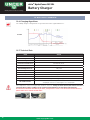
1
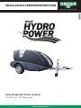
Installation & Operating Instructions
ENGLISH
Quality Tools for Smart Cleaning
Fully Integrated Trailer System
with RO Filter + 750l Water Tank
Status: June 2014
www.ungerglobal.com
1
nLite® HydroPower RO XXL
Quality Tools for Smart Cleaning
Table of contents
TABLE OF CONTENT
Introduction..................................................................................3
Copyright UNGER GmbH..............................................................3
Marking through attention symbols...........................................4
Guarantee.....................................................................................5
1. Safety - General warnings.......................................................6
2. Before bring in use...................................................................8
2.1. Accomplish water supply and water outlet....................8
2.1.1. Accomplish water supply......................................8
2.1.2. Carry away water..................................................8
2.1.3. Anti- legionella bacterium measure.....................8
3. Operation..................................................................................9
3.1. General............................................................................9
3.2. Visual perception..........................................................91
3.3. Component review........................................................10
4. Operation Control Box...........................................................12
4.1. Control box - general info.............................................12
4.2. Operating left/right flow...............................................12
4.3. Operating RO- system...................................................13
4.4. Alarm/display messages..............................................13
4.5. Trailer............................................................................14
5. Turn off...................................................................................16
5.1. Spray equipment...........................................................16
5.2. Cleaner..........................................................................16
5.3. Water outlet...................................................................16
5.4. Put away cleaner...........................................................16
5.5. Transport.......................................................................16
5.5.1. General................................................................16
5.5.2. Storage at freezing temperatures......................16
6. Service....................................................................................17
6.1. General..........................................................................17
6.2. Maintenance diagram...................................................17
6.2.1 General.................................................................17
6.2.2. Periodic maintenance.........................................17
6.2.3. Ion exchange resin filter (DI) changing resin bag(s).........................................18
6.2.4. Changing osmosis membrane (RO)....................18
6.2.5. Adding membrane preservative medium...........18
6.2.6. Carbon water filter..............................................18
6.2.7. Maintenance of the trailer..................................18
6.2.8. Maintenance at expense of technicians..............19
6.3 Description daily control................................................20
6.3.1. Trailer..................................................................20
6.3.2. Valves + manometer............................................20
6.3.3. Machine parts.....................................................20
6.3.4. Spray equipment.................................................20
6.3.5. Electrical parts....................................................20
6.3.6. Water tank...........................................................20
6.3.7. Ion exchange resin filter.....................................20
6.3.8. Osmosis filter membrane...................................20
7. Malfunction table...................................................................21
7.1. Malfunctioning table.....................................................21
7.2. Troubleshooting diaphragm pump...............................22
8. Technical data.........................................................................23
8.1. General..........................................................................23
8.1.1. Machine statement.............................................23
8.2. General data..................................................................23
8.3. Accessories...................................................................23
8.4. Technical data trailer....................................................24
Technical Data Overview......................................................25
Technical Data Diaphragm pump........................................26
9. After care................................................................................28
9.1. Storing the cleaner.......................................................28
9.2. No - activity during long period....................................28
9.3. Remove installation environment friendly...................28
10. Battery Charger...................................................................29
10.1. Before charging...........................................................29
10.2. General........................................................................29
10.3. Installation..................................................................29
10.4. Function.......................................................................29
10.5. Trouble shooting and service......................................29
10.6. Charging Algorithms...................................................30
10.7. Technical Data.............................................................30
Read this original instructions manual attentively before operating the Pure Water filter system. Take all safety instructions in mind!
2
www.ungerglobal.com
nLite® HydroPower RO XXL
Introduction
INTRODUCTION
When choosing the Unger nLite® HydroPower RO XXL pure water filter system, you have decided in favour of a high
quality product.
In this system two desalination filters are working. The minerals responsible for producing hardness and the
conductivity (TDS value) are removed from the water. First the main quantity of minerals is filtered out by a reverse
osmosis membrane (RO). After that a deionisation filter (DI) filters the rest to achieve a 100% pure water result.
ENGLISH
Quality Tools for Smart Cleaning
Complete desalination is based on the principle of reverse osmosis, supported by ion exchange in this system.
The application of this treatment has the following advantages:
• A water fed pole and a brush are all that is needed for glass cleaning.
• Prior to system installation and start-up it is essential that you observe the safety
regulations & instructions for installation and maintenance contained in these instructions.
• The manufacturer is not liable for the function of the device:
• When handling is not in compliance with regular use.
• When used for applications not mentioned in the manual (use other than intended),
• When failing to comply with safety regulations.
The points mentioned beneath have a risk of damage:
• Operating and installation errors.
• Wrong usage of loose resin (Overfill, expansion of resin).
• Parts of the system are opened incorrectly.
• Replacing spare parts that are not included in the official Unger spare parts price list.
• Performing unauthorized modifications to the design.
• Non- compliance with safety regulations (e.g. anti-freeze protection).
• Use of chemical additives.
• Insufficient maintenance.
© Copyright UNGER GmbH
Nothing from this expenditure can be multiplied and/or made public by means of print, photocopy, microfilm or by
what means, without preceding written authorisation of UNGER Germany GmbH.
This also applies to the accompanying pictures, drawings and diagrams.
UNGER Germany GmbH preserve themselves the right to modify components at each desired moment, without
preceding or direct announcement to the consumer.
The contents of this expenditure can be also modified without preceding warning.
For information concerning adjustments, maintenance activities or repairing where there it is not referred in this
expenditure, you are requested to get in touch with your supplier.
This expenditure has been composed with all possible care.
UNGER Germany GmbH does not take any responsibility for possible errors in this expenditure or for the impact of it.
Date of issue: June 2014.
www.ungerglobal.com
3
nLite® HydroPower RO XXL
Quality Tools for Smart Cleaning
Attention Symbols
MARKING THROUGH ATTENTION SYMBOLS
In this user guide and on the machine some areas can be emphasised with attention symbols.
These attention symbols indicate on a possible danger or point of interest.
Ignoring such indications can lead to physical wounds, machine - or company damage.
User guide:
Before you take the cleaner in operation you must always go through this user guide attentively and keep
him within hand range.
Please note:
If not (or not exact) follow up of these work - and/or service instructions can lead to serious personal
injury, deadly accident, damaged machine - or company damage.
Electric tension:
These instructions indicate the correct handling with electric components of the machine.
The areas on the machine, marked with this symbol, containing electric components and can never be
opened or adapted by unauthorized person.
Toxic substances:
When the machine has equipped to work with chemical products, ignoring these points of interest can
lead to irritations, wounds to even deadly result. Follow the product instructions always conscientiously.
Fire danger:
These instructions indicate on operations which can cause fire, which can lead to serious damage and
personal wounds.
Heat danger:
These instructions indicate on dangers for heat and hot surfaces, which can cause personal wounds.
Marked areas on the machine can be never touched or approached when the machine is in operation and
even at an eliminated machine attentiveness remain necessary.
Indication:
These instructions contain information or recommendations which ensure the simplified functioning and
a safe use.
4
www.ungerglobal.com
nLite® HydroPower RO XXL
Guarantee
GUARANTEE
Guarantee period: see supplied guarantee proof.
ENGLISH
Quality Tools for Smart Cleaning
Included:
General components which has gone perceptible failure as a result of material errors, production errors or poor labour performance.
Electric components which falls under this provision.
Guarantee period:
Have delivering person confirm any damages to the packing.
Reports of shipping damages that have not been confirmed by the transport company cannot be accepted.
Damage detected only after start-up must be reported to the dealer without undue delay, at the latest, however,
6 months after purchase. The dealer‘s invoice is absolutely necessary to confirm the date of purchase.
In addition, the general terms and conditions of Unger apply.
Failures are exclusively covered by guarantee if an entirely filled in and signed guarantee proof is sent to UNGER Germany GmbH:
UNGER Germany GmbH
Piepersberg 44
42653 Solingen,
Deutschland
For an application to guarantee you must contact immediately your supplier.
A guarantee application which is too late communicated, is no longer handled.
Guarantee attribution:
• The guarantee attribution occurs by repairing to the faulty component.
• The shipping costs are always at the expense of the customer.
• The replaced faulty components become property of UNGER.
Not included in the guarantee:
• Indirect arisen damage.
• Normal wear.
• Damages arise of failure or incompetently use.
• Damage incurred during loading, unloading or transport.
• Damage by freezing.
• Damage which is too late reported.
• Costs of repairing by third parties.
Guarantee expires:
• At change of owner.
• At modifications/repairing by a not recognised UNGER repairer.
Liability:
UNGER Germany GmbH as a manufacturer cannot become responsible for personal lesion, damage to properties of third parties,
company damage, production loss, capital loss, loss of goods and such, which has arisen by poor or too late supply of sold article,
irrespective of the cause of this.
UNGER Germany GmbH cannot also become responsible for the possible detrimental impact of chemical cleaning products which are
added.
The trailer is designed in such a way to be safe to use and maintain.
This applies to the uses, circumstances and guidelines described in this documentation.
Everybody who works with or on the trailer must therefore read this documentation and follow the instructions it
contains. In the event that the trailer is used by the employees of a company in the course of their work, their employer is responsible
for ensuring that they are familiar with and follow the instructions in this documentation.
Additional safety measures related mainly to working conditions may be in force in the company or country in which this trailer is used.
This documentation does not describe how these measures must be complied with.
It does, however, contain all the information you will need about the actual trailer.
If you have any doubts, ask the respective government official or your safety officer.
Conversions and modifications to the device:
Due to safety reasons, unauthorized modifications are not allowed. Original parts and accessories are specifically designed for this device.
Any liability by the manufacturer for damages resulting from modifications to the device or from using parts other than original parts is
excluded.
www.ungerglobal.com
5
nLite® HydroPower RO XXL
Quality Tools for Smart Cleaning
General Warnings
1. SAFETY - GENERAL WARNINGS
General:
Please observe the applicable rules and regulations, as well as the effective accident prevention regulations.
UNGER is not liable for any occurring water damage. Make sure that the area of application has sufficient water
drainage. Close feed valve in case of prolonged shut-down times (e.g. weekends).
The nLite® HydroPower RO XXL can be exclusively used by trained and qualified persons who have been instructed in the service of it and explicitly with the service of it have been charged.
For this reason a complete knowledge of this guide is necessary to avoid damage to yourself, third parties,
objects or to the machine self. The nLite® HydroPower RO XXL is not suitable for use by children or young people! Not instructed personnel or persons with limited psychical, physical skills may not use the machine.
If the machine is used by other persons than you must as an owner inform the user of the safety regulations. The
use of the nLite® HydroPower RO XXL falls under the applying national provisions. Beside the instructions for
use and in the country where the machine is used applying binding regulations concerning accidents prevention,
also the recognised technical rules for safely and judicious work must be observed.
Each working method which can be dangerous for safety matters must be avoided.
Hoses:
Hoses, fittings and joints are important for the safety of the machine.
Use only by the manufacturer approved parts! Do not use the hose as a draft cable.
Look out for tripping hazard when the hose is unrolled from the reel.
Please note: block the hose reel with the locking handle and hook, couple the left/right flow reel hoses to the
RO- connections at transporting the trailer (so the hoses are locked & could not unroll!)
Uncouple the hoses again (after transport) from the RO- connections when using the reels of the cleaner!
Spraying:
The water hose may not be aimed on yourself, persons, animals, installations under electric tension or at the
machine itself.
Never spray electric installations with water: danger for persons, short circuit danger.
Carry safety clothing, safety optical device, if necessary!
During the use keep all protective coverings and doors (cap) of the machine closed!
Any surface that becomes wet must be identified with appropriate signage to direct pedestrians and workers
away from work area. During wintertime, it is important to avoid water pooling, which could freeze, creating a
dangerous slip hazard. Do not clean sensitive parts with the jet.
Never spray water from an unstable duty station/place (ladder, small boat, wharf...).
Spray equipment:
Stop the machine, if spraying equipment need to be exchanged. Fix the spray equipment correctly.
Take the necessary safety precautions when spraying!
Machine:
Never take the nLite® HydroPower RO XXL in use without water. Even a brief lack of water can lead to
damages! When the machine is connected to the drinking water supply, the existing regulations about that must
be observed (EN 1717). The machine must stand on a stable horizontal base & with the trailer in braked position!
Working at artificial light: if daylight offers not sufficient visibility during the use, the use of adapted
impermeable lighting armature(s) stretches to recommendation. In spaces provide with standard lighting these
must remain on wide distance of the water jet. Never work outdoors during a storm or bad weather.
Fixed adjustments of the machine may not be modified under no circumstances.
The nLite® HydroPower RO XXL has been made in running order and tested by UNGER according the safety
standards. When the machine is in use these can never be left behind unattended.
Do not spray materials containing asbestos or other health-hazardous substances.
Water outlet:
Take care for a sound and smooth water outlet of the concentrate.
Traffic:
Protect piping and cables with protective boards/plates when they are lying on a roadway.
6
www.ungerglobal.com
nLite® HydroPower RO XXL
General Warnings
1. SAFETY - GENERAL WARNINGS
DI Ion exchange resin filter:
Transportation: ensure that the DI tank is properly secured to the related moulding in the trailer.
This device may cause danger if it is improperly installed, not regularly maintained or not used as intended.
Use this device only for water treatment to reach an optimal water quality for glass cleaning. Any other use,
especially water treatment for food production (e.g. beverages) is considered as non- intended and not allowed.
When operating with water other than from drinking water system, e.g. from a well, a water analysis must be
performed prior to application to determine if the water is suitable.
Excess impurities in the water may have an adverse effect on system performance and cleaning result.
Resin can cause skin irritation. Avoid skin contact.
If you use loose resin: Pay attention to not overfill the vessel. Only use new, saturated wet resin. Never use dry
resin as this will expand a lot and can destroy the system.
ENGLISH
Quality Tools for Smart Cleaning
Possible failures at spraying activities:
• Trip hazard to the general public when using trailing hoses.
• Slip hazard presented from wet pathways.
• Slip hazard for operator when concentrating on work.
• Falls from height when working on flat roofs.
• Electrocution from poles coming into contact with overhead power source.
• Injuries to others from falling poles or fabric of the building that may be dislodged.
• Injury to others from falling poles caused by incorrect handling or failure of pole.
• Injury through incorrect manual handling of poles and other equipment.
• Spread of legionella disease through poor maintenance of system.
• Hazards from carrying tanks, systems and equipment that are overloaded, unstable, unsecured or incorrectly
installed within a vehicle.
Personal safety measurements:
Do not drink the water produced by this system.
Water produced by the machine is too pure and will rob the body of vital minerals and nutrients if imbibed in
quantity.
When operating with a tap waterline, it must be assured that the connected water hose is equipped with a nonreturn valve to prevent water flowing back into drink water line!
Trailer:
We recommend to transport the trailer without water, a filled water tank could affect the riding behavior of the
trailer. Do not climb on the trailer if it is not connected to a towing vehicle. No permitted use as a lifting device
for either people or animals! None of the safety devices may be removed or put out of operation.
Ensure that nobody can become trapped, do not exceed the maximum load/maximum permitted ball thrust (see
type plate). A valid driving licence is obviously required for driving with the trailer.
Your trailer should ALWAYS be provided with good readable, official license plate according to your country
regulations. Place the plate on the back side of the trailer and make sure it is properly illuminated by the license
plate light! Also note on a good tire pressure!
Pay attention to the risk that the trailer might skid or swerve, you should also adjust your driving speed
depending on road conditions and the load you are pulling.
This applies especially to bends, notice that your car reacts differently with the trailer coupled! In runs with a
brake, trailer loaded, it is important that you limit the speed for handling and manageability of your combination.
Do not handle this speed limit as striving but as absolute maximum!
Hand brake:
Pay attention to risk of accident due to failure of the hand brake! If the trailer is to be uncoupled from the
towing vehicle, the hand brake must be applied and the trailer must be secured by means of two additional
wheel blocks. At parking or placing of the whole combination, tighten also the hand brake!
Danger - risk of injury! The trailer may roll back before the full braking force is applied!
Ensure that there is sufficient space when parking the trailer.
Breakaway cable:
Always route the breakaway cable through the breakaway cable guide ring!
See photo beneath.
Attach the breakaway cable in such a way that cornering is not impeded.
The breakaway cable must not be wrapped around the jockey wheel.
Observe country specific regulations when attaching the breakaway cable.
Danger due to uncoupling of the trailer!
Jockey wheel/ support arm: Ensure that the jockey wheel is seated securely
and that the support arm is secured, before driving on the road!
www.ungerglobal.com
7
nLite® HydroPower RO XXL
Quality Tools for Smart Cleaning
Before use
2. BEFORE USE
For each start up all substantial parts of the nLite® HydroPower RO XXL must be checked by taking them in
consideration like for example: all the cleaning equipment is still fixed firmly, check hoses and electric wiring on
damages. Persuade yourself of the safety regulations from previous chapter.
Before starting, check the nLite® HydroPower DI on cracks. Be sure the cover is in locked position.
Keep discharge line open and hold yellow lever down to remove trapped air from system.
For use only with drinking water.
2.1. Accomplish water supply and water outlet
2.1.1. Accomplish water supply
The water supply pipe can be connected (towards circumstances) on their own water supplies
(under pressure) or on a drinking water supply with a water barge. When the machine is connected to the
drinking water supply, the existing regulations about that must be observed ( EN 1717 ).
Water supply under pressure:
Maximum hose length 50 m (160 ft), minimum hose diameter (inside) 12.7 mm (1/2”).
Check the water pressure using a water meter.
2.1.2. Concentrate water
Check that all water outlets have been correctly connected.
Take the necessary measurements so that the water concentrate is suitable enough to drain.
2.1.3. Anti- legionella bacterium measure
If the machine has stood still some time, the water in the machine must be drained above an evacuation.
Stationary water that becomes hot (between 20 - 55°C) can cause the legionella bacterium.
• Clean therefore piping and tanks on a yearly base.
• Remove possible sediment.
• Rinse periodically.
8
www.ungerglobal.com
nLite® HydroPower RO XXL
Operation
ENGLISH
Quality Tools for Smart Cleaning
3. OPERATION
3.1. General
Please make yourself familiar with all the components of nLite® HydroPower RO XXL before you start to work.
See below description: All the technical data you can retrieve at the end of the manual.
3.2. Visual perception
Control box
Hose reelS
nLite® HydroPower DI
3
4
2
Water tank
Ion exchange
resin filter (DI)
nLite® HydroPower DI
(DI24T)
Reverse osmosis filter (RO)
5
Carbon PRE-filter
2
4
4
Pneumatic
spring
7
6
1
1.
2.
3.
4.
Pressure gauge
Diaphragm pump
Battery
space
Storage area FOR
WATER FED POLES
www.ungerglobal.com
Battery charge
connection
Water IN connection
Water OUT connection
FastLock™ opening lever
Handles to carry and
open the vessel.
5. TDS-Meter
6. Vessel
7. QuickChange™ Resin Bag
9
nLite® HydroPower RO XXL
Quality Tools for Smart Cleaning
Operation
3. OPERATION
3.3. Component review
Battery
The type of battery is a sealed gel block battery with specs: 12V - 210Ah.
Pressure gauge
On the manometer you can read the pressure of the incoming water, before the RO-system.
The pressure must be below 5 Bar at all times!
Trailer
The complete water filter systems ands the water tank are build on a trailer.
Water tank
The water tank provides a buffer of pure water and prevents that there may appear pressure impulses
in the water system. The water tank has a volume of approx 750 Litres. Below the water tank there’s a
drain valve provided to drain the water from the tank (see picture right). At the back side of the trailer
there’s a cap which can only be used to check the water level of the water tank or for any maintenance
activities in the tank.
Note: the cap on the water tank can NOT be used to fill the tank. Filling through the cap may in no
case be done, the supplied water will not pass through the RO & DI and so it is no pure water.
Unger is not responsible for possible damage caused by improper use of the cap.
Please also add no other products (such as chemical products, ...) in the water tank through the cap!
Water Pre-filter
The water supply will be filtered with the carbon water filter and ensures the durability of the osmosis
CONCENTRATE
membrane.
Osmosis system
Reverse Osmosis is a separation process in which feed water
permeates a selective membrane. Dissolved as well as undissolved
materials are rejected by the membrane and carried away in the
concentrate water stream. The purified water contains only a fraction
of these materials, with TDS - total dissolved solids (a measure of the
salt content in water) of the original feed water concentration.
Containing salts are rejected by the
membrane and do not enter the product
tube. The concentrate water exits on the
side of the element opposite to the feed.
TAB WATER FEED
enters into membrane layers.
Applied pressure forces raw
water across the membrane
into the product tube.
PURE WATER
collects in the product tube and
can be output from either end
of the membrane element.
PRODUCT TUBE
Here the filtered water
flows into the tank.
Ion exchange resin filter
The ion exchange resin filter is usually a stand alone solution to purify water. In the nLite® HydroPower RO XXL
it works behind the RO-membrane as a polisher to filter out the final minerals out of the water and to deliver
100% pure water (0 ppm).
Hose reels
The nLite® HydroPower RO XXL is standard equipped with 2 reels with each 100m.
Always secure/block the reel(s) after use and before transporting the trailer.
Disconnecting the reel coupling: pull the plastic coupling to loosen from the RO- connection, unroll the hose reel
loosening the reel lever (see photo).
Connecting the reel coupling: couple the flow reel hose coupling(s) to the RO- connection by clicking/pushing the
plastic coupling to the connection.
Secure the hose also by the reel lever so the hoses are locked & could not unroll!
Note: uncouple the hoses again (after transport) from the RO- connections when using the reels of the nLite®
HydroPower RO XXL!
The green bumpers protect the connectors when the hose is rolled back.
COUPLINGS
10
HOSE REEL
www.ungerglobal.com
nLite® HydroPower RO XXL
Operation
3. OPERATION
Support arm
The support arm is mounted at the back, underneath the trailer on the light bar.
Watch out for the crossover point of the support arm at a filled/unfilled water tank.
Pulling out the support arm can be done by the red handle, the support arm folds now, set the support arm fixed
to the ground by the central bolt and with help of a wheel bolt/crank.
Pull back the red handle and push the support arm upwards to return to fold.
Pay also attention to compensation of the spring on the axles. If the supports are lowered completely, they will
take the entire weight of the load and can become damaged.
On soft ground, suitable sheet/plate material has to be laid under the supports. To balance the position of the
trailer, the supportarm length can be adjusted with a 19mm key at the screw behind the red handle. The standard
key for car tires should fit.
ENGLISH
Quality Tools for Smart Cleaning
19mm screw
to adjust length of
the support arm
Diaphragm pumps
The machine is equipped with 3 diaphragm pumps.
Two pumps are used to supply the flow to the hose reels (left /right flow).
The other pump is used to feed the RO- system water supply.
Type of pumps: 8030 series : 4.5 GPM - 5.7 ltr/min
Note: restrictions on the inlet may cause vacuum levels to reach the fluid vapour pressure, causing cavitation,
degassing, vapour lock and a loss in performance. Inlet pressure must not exceed max. 2,1 bar
(30 psi).
Cover cap
The cover cap could be opened/closed easily by means of 1 lock below the control box
(see picture). !! Keep the cover cap closed during/starting the cleaning activities !!
Pay attention: make sure that the cap closes properly in the closing mechanism before you drive
on the road.
Battery charger
The battery charger is located in the provided space in the trailer.
Mount the charger with LED’s facing up and cable downwards. This will
maintain an efficient cooling and a maximum output current during the
whole charging cycle. Do not extend charging cables. That may affect the charging result. Connect to battery
loader (output) to the electric connector indicated in the pictures.
Connect the input 230 V AC cable to your power supply. Please follow the safety measurements!
TDS meter
The TDS meter is situated in the trailer against the water tank and beside the DI- filter.
The meter measures the TDS value at the water tank, if the alarm value is reached the control box will
indicate a TDS alarm, see chapter 6 - maintenance for solutions on this alarm message.
RO- input valve
This valve opens the water supply to the RO- system at filling (see picture left).
The input valve is situated after the RO- water supply connection and below the water carbon filter.
www.ungerglobal.com
11
nLite® HydroPower RO XXL
Quality Tools for Smart Cleaning
Operation
4. OPERATION CONTROL BOX
4.1. Control box - Overview
The UNGER Control Unit provides a simple operation of the two water
pumps, which deliver the pure water and the RO filling unit, which fills
the tank with purified water.
LEFT FLOW = Controls the pump for the left hose reel.
RIGHT FLOW = Controls the pump for the right hose reel.
RO FILLING = Controls the filling of the tank with purified water.
With the remote controls the left and right pump can be controlled from
a distance and you can switch between “wash” and “rinse” mode.
The remote control works on a distance of max. 100m in open area. If
buildings or plants are between the operator and the trailer, the reach
can be reduced.
Control Unit
4.2. Operating the left/right flow
1. Switch on the desired pump (left/right) by pressing the UP-button
.
2. Adjust the desired water output on the control box using the UP/DOWN-buttons
.
• The controller also provides an indication of flow rate (range: 0-99).
• The difference between wash and rinse mode is set by default at 30. This value can be changed
(see below “Rinse Speed Mode”)
• Appropriate wash speed adjustment : min. 40 - 70 max.
• Default recommended speed: 50 (washing) = 80 (rinsing).
3. If you press ENTER
again, you see the battery voltage. Example: BAT, 12.4
Note: At 14,0 ithe battery is fully charged, at 10,5 it shuts off.
4. When you press ENTER
once more, you are back to the flow rate FLO
.
5. To switch off the controller, press and hold ENTER
Remote Control
4.2.1 Remote Control
It’s also possible to use the remote control to switch the related pump (left or right) on/off or to change
between wash and rinse mode. The remote control allows you to change the flow from the place where you
are working (max. 100m in open areas).
WASH MODE (to select a normal flowrate for standard cleaning):
button on the remote control
• Push the W
RINSE MODE (to select a higher flowrate for rinsing the surface):
button on the remote control.
• Push the R
• ‘RIN’ appears in the control box display and the diaphragm pump delivers more flow boost.
The rinsing value is by default always 30 higher than the wash value, but max. 99.
(or according the set value in Rinse Speed Mode).
On the backside of the remote
control you can read if it is for
the left or right hose reel.
Please also note the channel
of each control for the case you
lose it. Example here: „Ch. 01“
FOR EXPERTS:
Calibration Mode:
In calibration mode it is defined when the system shuts off at “dead end” situations (e.g. interrupted waterflow, air in the line etc.). Pay attention: The default setting of 79 should NOT be changed. A higher value could damage the system as it shuts off possibly to late. A lower value
could cause that the system shuts off too early.
, you are entering in the CAL mode (calibration) - if that happened accidentally go
• When pushing both UP&DOWN buttons
back by pushing the ENTER button
button!
• This is a WATER PUMP controller: it will not work with air in the system. Air could cause false dead-end detection.
• Always prime your system before starting work.
• Repeated false dead-end detection (dE) indicates that the CAL value should be increased (less sensitive). But don’t set the CAL
value too high as this could cause damage to the pump.
+
to enter the CAL mode, press DOWN
to start
• There is as well an “AutoCalibration” function. Press UP+ENTER button
the “AutoCal”-mode (AUt). After some seconds the calibration value will be displayed and has to be confirmed with ENTER
Rinse Speed Mode:
The rinse water flow is always in same relation higher than wash flow. Default setting value: 30
longer, you are entering the setting mode for the rinse speed.
• If you push both UP&DOWN buttons
. The entered number is added to the washing speed when you activate
• You can change this value with the UP/DOWN buttons
rinsing. (Example: if you change value to 50: if wash is 40 then rinse is 90)
.
• Return to previous mode with the ENTER button
• ‘SET’ is displayed now on the display to confirm the new value.
12
www.ungerglobal.com
nLite® HydroPower RO XXL
Operation
ENGLISH
Quality Tools for Smart Cleaning
4. OPERATION CONTROL BOX
4.3. Filling the tank - producing pure water
The production of pure water works with the integrated RO- and DI-Filter. The produced
water is stored in the tank and led with the two pumps to the left and/or right hose reel.
So it is forwared into your water fed pole. Connect your water supply hose to the left
connection. Connect the concentrate water drain hose to the right connection and lead it
away from working area, so that it can drain. (Hose is not kinked, no adapter at end).
WATER SUPPLY (TAP)
CONCENTRATE
The lower control unit (RO FILLING) powers the RO booster pump.
until you read FIL in the
1. To start filling the tank, simply press and hold the UP&DOWN buttons
display.
ATTENTION: If you press the two keys too long, you get into the tdS mode. In this case return with the
button. (see description of this mode below)
2. The filling process starts until the float switch detects, that the tank is full.
3. While the solenoid valve is on and the tank is filling the FIL message flashes.
4. When the tank is filled, the diaphragm pump will stop and the battery tension will appear again in the
RO-FILLING display.
again.
5. To manually stop the tank filling, press and briefly hold the UP&DOWN buttons
The display will stop showing the FIL message.
Note: The solenoid valve will be turned off if the unit detects a low battery situation (below 10.5V).
FOR EXPERTS:
TDS Auto-Cut-Off
The unit monitors water purity in TDS (Total Dissolved Solids) in ppm (parts per million).
For a good cleaning result this should be 10 ppm or below. The unit can be configured with a TDS cut-off if this value gets too high.
By measuring the mineral content with the TDS- Meter you can determine the water quality.
The TDS-meter has a maximum reading of 50ppm.
• To monitor the water temperature (°C) press ENTER
until you read for example tP, 17C
• Press ENTER
again to monitor TDS reading in ppm: Example: tdS, _20 (a TDS higher than 50 is displayed with HI)
• When the TDS value rises above the TDS cut-off setting, the pump will be stopped. The display will show: tdS, StP
•
Note: When the controller is first turned on, the TDS cut-off is disabled for app. 60 seconds to allow any dirty water to be pumped out
buttons longer, you are entering the setting mode for the auto TDS value (tdS).
•
Note: if you push both the
Do not change this value! Return to previous mode with the
key.
4.4. Alarm/display messages
On the display different alarm messages can appear like described below:
ALARM
MESSAGE
CLARIFICATION
bAt
This message will start to flash when the battery tension is to low.
If battery is below 10.5V the pump will be disabled to protect the battery (unless low battery
cutoff is disabled). Connect the battery charger to charge the battery.
dE
Dead end detection, water flow is restricted (i.e. when the pole has been disconnected from the
hose, you stand on the hose or air is in the system).
Unroll the hose & check if these is not bend, reconnect the pole.
PS
Pressure switch activated or motor disconnected.
TDS HI
MAX. TDS value reached, replace the resin bags of the DI-filter
TDS StP
When the TDS value rises above the TDS cut-off setting the pump will be stopped.
The controller will display the left alarm message.
DISPLAY
MESSAGE
CLARIFICATION
FOB StP
Stop function activated of remote control
tP
Temperature indication
FIL
The RO- system is filling the tank with pure water
FUL
The tank is completely filled the with pure water
www.ungerglobal.com
13
nLite® HydroPower RO XXL
Quality Tools for Smart Cleaning
Operation
4. OPERATION TRAILER
4.5. Trailer
4.5.1. Coupling the tow ball coupling:
1. Manoeuvre the ball coupling over the trailer device.
2. Open and hold the ball coupling.
3. Turn the jockey wheel handle clockwise until the ball coupling locks in place.
4. Continue to turn the jockey wheel handle until the wheel is fully retracted.
The support shoe must be firmly engaged in the recess in the outer tube.
Caution: only permissible with DIN 5299 snap hooks - min. 70 (fire brigade snap hooks).
5. Open the clamp.
6. Pull the jockey wheel upwards as far as possible.
7. Tighten the clamp.
8. Connect the power cable to the towing vehicle.
9. Route the breakaway cable through the breakaway cable guide ring and loop it around the ball plate (see photos - see also the applicable country regulations for potential possibilities through coupling!).
Caution: lock the tow ball coupling correctly/safely to your riding vehicle in case you want to use a removable
coupling. Pay attention for possible loosening of the trailer, follow your national rules applicable on this subject!
See possible pictures for indication below.
10. Release the hand-brake lever.
11. Remove wheel blocks.
Note: The ball coupling consists of safety indicator 1 (these checks if the coupling is secured, the green cylinder
is visible when installed correctly) and wear-indicator 2 (these controls the wear limit of the ball coupling, at red
colour area replace immediately, the ball joint can hang out. The green colour is within acceptable range).
4.5.3. Operating the hand brake (see photo):
Applying: pull the hand-brake lever beyond the noticeable dead-centre position.
Releasing: press the locking button and keep it pressed. Push the hand-brake lever back through the dead-centre position to its original position. Always pull the hand-brake lever fully!
14
www.ungerglobal.com
nLite® HydroPower RO XXL
Operation Control Box
ENGLISH
Quality Tools for Smart Cleaning
4. OPERATION TRAILER
Checklist - Coupling and uncoupling the trailer:
COUPLING:
• Safely coupled?
• Hitch securely locked, visual control - noise control (clack!)
• Breakaway cable attached?
• Handbrake opened?
• Jockey wheel turned up and clamped?
• Electrical connection, do all the lights work?
• Support arm up completely and locked?
• Forgot any loose parts on or in the trailer?
• Tire visual inspection
• Wheel blocks
DISCOUPLING:
• Trailer saved from rolling away, hand brake, wheel chocks!
• Disconnect the electrical connection!
• Uncoupling!
• Lose Breakaway lose cable!
• Extend support arm!
Technical check:
• Mirror adjustment and clear visual from the car?
• Check the cable guide of the trailer
• Perform lighting test
• Check ball joint lubrication
• Perform air pressure check the tires on the trailer
10 basic rules
1. The vehicle to move to the trailer when coupling.
2. Build electrical connections between towing vehicle and trailer.
3. Place or attach brake away cable to the trailer tow ball.
4. Always pull the jockey wheel up to the stop and arrest.
5. Release hand brake of the trailer before starting
6. Trailer is wider than the towing vehicle: What “fits” at the front does not automatically “fit” in the rear..
7. You’re not driving a car - it’s now longer, wider and engine power is different.
8. If the trailer is yawing: No accelerator pedal, clutch pedal, keep steering straight.
9. At crosswind think (overtaking trucks, drive over bridges, clearings)
10. The directing person is pointing in the direction in which is driven and is not in the in the direction where to steer .
He must be seen in the mirrors.
#
COLOUR
NAME
1
yellow
left indicator
2
blue
fog lamp
3
white
mass
4
green
right indicator
5
brown
right rear indicator
6
red
left and right brake lights
7
black
left rear brake
8
grey
reversing light
white/black
mass (for poles 9-12)
9
10
11
12
13
www.ungerglobal.com
15
nLite® HydroPower RO XXL
Quality Tools for Smart Cleaning
Turn off
5. TURN OFF
5. Turn off
When you interrupt or stop the cleaning activities, be sure to bear in mind the following instructions in order to be
able to switch off the nLite® HydroPower RO XXL in the right way.
5.1. Cleaning equipment
Disconnect your pole, brush, or other equipment and put it away. Make sure, the machine is powerless.
Close the water supply. Roll up the hoses.
5.2. System
Drain the water from the supply tank (by means of a drain off valve beneath the trailer).
Slightly clean the nLite® HydroPower RO XXL. Close the protection cover and bolt the locks.
Guard the manual and other information data sheets within reach.
5.3. Water outlet
See point 1 - safety & point 2.1.2.
5.4. Storage of nLite® HydroPower RO XXL
Store the trailer in a dry and frost-free place at a horizontal and stable subsoil.
Pull the trailer brake. Turn the jockey wheel downwards and bolt it.
Untie the safety cable as well as the electricity wire from the trailer. Uncouple the trailer from the pole.
5.5. Transport
5.5.1. General
Close the protection cover. Check the pressure of the tires (ca. 4 bar) and profile depth.
Couple the trailer and make sure that the shaft is connected firmly.
By pulling the shaft powerful up you can check if the coupling is put on firmly.
Turn the jockey wheel and lock it.
Caution, make sure the jockey wheel is turned into the driving direction.
Please also ensure that the nose wheel will not touch the brake system.
Set the jockey wheel like shown in picture on the left.
Attach the breakaway cable carefully on the towing hook eye it’s meant for.
This cable is a safety precaution and is used as an emergency break, when suddenly the coupling gets loose
during driving. Attach the electrical cable for the lighting, and check it.
Unlock the hand brake (if present) and remove the wheel blocks. The machine must always be provided with
a good readable, official registration plate, according to the applicable regulations to your country.
The plate must be attached properly on the back and the lighting lights the complete plate.
5.5.2. Storage at freezing temperatures
Frozen water in the cleaner could damage parts of the nLite® HydroPower RO XXL.
Remove the water from the tank at frost temperatures, turn the jockey wheel of trailer completely down and
open the drain valve on the bottom of the front of the trailer.
16
www.ungerglobal.com
nLite® HydroPower RO XXL
Service
ENGLISH
Quality Tools for Smart Cleaning
6. SERVICE
6.1. General
All maintenance activities must happen at an disconnected machine and hoses without pressure.
Checking the electric components can happen exclusively by an expert. Exclusively accessories and replacement
components which have been approved by the manufacturer can be used. Directly after the activities all
securities- and protection parts must be assembled, before the machine is put in functioning.
“a golden rule” that contributes to a perfectly working machine with few problems, is well the following:
A DAILY CONTROL AND CLEANING OF THE MACHINE FREQUENTLY PROLONG THE LIFECYCLE!
To ensure a perfectly working and reliable system, you have to assure a regular thorough maintenance by
experienced technicians. Best would be to sign a maintenance contract.
6.2. Maintenance diagram
6.2.1 General
Check the trailer system daily by means of the maintenance diagram. You find the maintenance plan on the
following pages. If this is not, then you need to consult the proper maintenance technicians.
PAY ATTENTION: Always secure the trailer with wheel blocks before starting any maintenance works!
6.2.2. Periodic maintenance
Check all the cables, hoses, brushes & couplings.
Check the wheel bolts/ ball clutch/plug/lights/good tyre pressure of the trailer.
Periodically inspect the nLite® HydroPower DI system during use. Ensure hoses are
properly attached. Inspect system for leaks and proper fit of top cap assembly.
After each use.
Changing osmosis membrane
if TDS value is above 10 and can
not be lowered by changing the
resin
Changing resin bags
If the displayed TDS value is
displayed higher than 10 on the
control box display.
Changing carbon filter cartridge
3 times per year
Lubricate or oil all sliding or jointed parts of the overrun device.
Check on possible wear of the wheel brakes/ bearings/brake lining.
yearly
6.2.3. Ion exchange resin filter (DI) - changing resin (bags)
Instructions:
Shut off tap water supply and open pole tubing line (on top). Drain the water from the DI.
Open the vessel by the big yellow lever. This includes a pressure valve, so pressure can be released easily
before opening. In one movement you can press the top cap slightly down and use a counter-clockwise 1/8
turn to release top cap assembly; remove and set aside. Reach into housing and remove exhausted resin
bag(s) by hand, discard according to local regulations. Now, simply remove the used bag and insert a new
one! Be sure to seat bags with zip-tie facing up and sewing in parallel to vessel ledge.
Otherwise resin capacity will not completely be used and ppm value is too high. Each bag is made from a
water permeable material and contains a pre- proportioned amount of Unger High Capacity Premium Grade
Virgin Mixed Bed resin. Re-install DI System & test TDS system.
Resin Change:
You have to change the resin bags if a message appears on the control box display if the TDS adjusted limit
is reached, fill the DI with new resin bag. Since the DI resin filter is used at different filling points with various degrees of hardness, the available quantity of completely desalinated water differs.
The QuickChange™ resin bag or the loose resin must be replaced.
Raw water quality can be determined in various ways.
a) Information from responsible water works (indication of overall hardness).
b) By measuring the mineral content with Unger TDS- Meter (on the steering display)
Note: Unger does not recommend the use of bulk resin with nLite®HydroPower DI systems. The use of bulk
resin, with widely varying properties, may cause damage to the system due to excessive expansion when
water is introduced. Overfilling the systems will also cause damage. Dry resin expands more than wet.
www.ungerglobal.com
17
nLite® HydroPower RO XXL
Quality Tools for Smart Cleaning
Service
6. SERVICE
6.2.4. Changing osmosis membrane (RO)
Determine experimentally if the osmosis membrane, rather then the DI, need to be
changed when the TDS value is reached. If the water flow rate significantly
decreases, you have to replace the membrane.
To change the osmosis membrane you have to drain the water from the osmosis
system. Make sure the system is pressureless before exchanging the membrane!
You can change the membrane only at the side like indicated on the picture left,
loosen the bolts and uncouple/unscrew the piping. Remove the membrane by pulling out.
Place a new membrane, connect piping and lock the membrane housing.
Note: be aware, the water flow rate also decreases at lower temperatures!
Avoid any abrupt pressure or cross-flow variations on the spiral elements during maintenance or other
sequences to prevent possible membrane damage.
6.2.5. Adding membrane preservative fluid
When the system, e.g. in winter, is stored unused for long periods of time, there is a risk of blockage of the
membrane and thus damage to the filter and no good filter results. For this reason, a special care agent
must be filled in order to avoid this blocking.
6.2.6. Carbon pre-filter
The carbon prefilter ensures the durability of the osmosis membrane.
Replace the filter cartridge (5 µ) of the carbon water filter 3 times per year.
Before dismantling the bowl (cartridge filter) you should first release the pressure.
The red button on the carbon filter need to be pushed to purge the filter.
Drain the water from the filter bowl before replacing the cartridge.
Loosen the bowl by the special filter tool. Replace the filter cartridge and every damaged parts (O-ring, ...) to
ensure good performance and water- tightness of the whole filter.
6.2.7. Maintenance of the trailer
Lubricate or oil all sliding or jointed parts of the overrun device every 12 months (see photo).
Lubricant Type: multi-purpose grease conform to DIN 51825
Check regularly for dirt, corrosion or damages.
Check regularly the ball clutch on good operation, potential cleaning and greasing.
Check after the first time the wheel bolts of the trailer and, if necessary, fasten the wheel bolts.
Follow the good torque moments (see also technical data 8.4). Repeat this always when a wheel is loosened,
for example if a tyre is changed (tighten wheel bolts crosswise). White rust on hot-dip galvanized vehicle
parts does not affect safety and can be reduced by means of the following measures:
- Ensure good ventilation when parking or storing hot-dip galvanized parts.
- After winter operation, wash the hot-dip galvanized surfaces with clean water.
18
www.ungerglobal.com
nLite® HydroPower RO XXL
Service
6. SERVICE
6.2.8. Maintenance at expense of technicians
ENGLISH
Quality Tools for Smart Cleaning
For further maintenance we advise to contact your distributor concerning a maintenance contract.
The maintenance applies to normal company circumstances. At heavy circumstances you can communicate this so this can
be taken into account.
It is recommended to carry out the preventive maintenance by a competent service technician according to this
maintenance diagram, to be able to remain use of the machine up to maximum and also to be able to claim the guarantee
conditions. To be able to guarantee a good and regular maintenance, we advise the owner/user at strongest to make an
appointment concerning a maintenance turn.
www.ungerglobal.com
19
nLite® HydroPower RO XXL
Quality Tools for Smart Cleaning
Service
6. SERVICE
6.3 Daily control
6.3.1. Trailer
GENERAL: Check the trailer entirely for screws coming loose, cracks and/or breakages of the welded joints.
Keep the machine as clean as possible to avoid dirt, water, oil and spilled fuel having a unfavourable effect.
Double check the tire pressure, brakes, closing of the cap, lights ...
This is necessary for your own good and other peoples safety on the road.
6.3.2. Valves + manometer
At switched off machine, the manometer must reflect 0 bar.
At a maximum performing machine, this means operated at full load working engine, the manometer can
not indicate more than the maximum pressure indicated for your machine.
6.3.3. Machine parts
Check the hoses, piping, DI, RO and connections on external damages and leaks.
If damaged or leaks these must be immediately replaced.
6.3.4. Cleaning equipment
Check poles, brushes, adapters etc. on leaks, external damages and hair cracks.
If damaged or at leaks, these must be immediately replaced.
6.3.5. Electrical parts
Check visible electric wiring and components on external visible damages.
If damaged, replace the concerning parts.
Note: pay attention when replacing the battery when damaged.
The weight of the battery is 67 kg, use lifting equipment or raise the battery with two people.
6.3.6. Water tank
Check the water tank on external damages and leaks.
Check when the tank is filling if the float system works properly.
6.3.7. Ion exchange resin filter
Periodically inspect the nLite® HydroPower DI system during use. Ensure hoses are properly attached.
Inspect system for leaks and proper fit of top cap assembly.
Take care when working to ensure there is enough slack in water fed pole tubing.
This tubing is connected to the top of the unit, and excessive tugging may cause the system to tip over.
6.3.8. Osmosis filter membrane (RO)
Daily inspect the functioning of the osmosis system through determine the water flow rate quality.
Change the membrane if necessary. Check the system on possible leaks and visible damages.
20
www.ungerglobal.com
nLite® HydroPower RO XXL
Malfunction table
7. MALFUNCTION TABLE
At a possible malfunction one can consult the table mentioned below and if you obtain on this basis no solution, we advise to
contact a DiBO- technician and/or a recognized DiBO- representative.
ENGLISH
Quality Tools for Smart Cleaning
7.1. Malfunctioning table
Malfunction
Machine does not start
Cause
Solution
Battery insufficient
Recharge and/or replace battery
Control box switched off
Switch on the control box
Rest malfunctions
Consult an expert
Carbon filter blocked
Replace filter cartridge
Air in water supply (leaks in water
supply)
Put power off!
Repair leaks in supply.
Spray equipment blocked.
Clean or replace
RO- input valve defective at filling
Consult an expert
Closing mechanism fault of cap
Key contact and/or closing
mechanism defective
Push the locking pin to open and replace
if necessary
Insufficient braking of trailer
Excessive friction losses or
corrosion on the drawbar
Remove dirt/corrosion from transmission
system + remove brake and then check
that the system operates smoothly
Consult an expert
Instable and to weak pressure
Damage caused by impact during
manoeuvring
Overheating of the brakes of trailer
Hand brake not released
Jockey wheel blocking linkage
Release hand brake
Release jockey wheel and move into the
correct position
Jerky motion or braking/trailer brakes
when towing vehicle stops accelerating/
overrun device makes noise.
Shock absorber defective.
Replace shock absorber.
Trailer brakes during reverse travel.
Corrosion and/or lack of wheel brake
lubrication.
Remove any dirt and corrosion + lubricate
again.
Arrange for worn brake shoes to be
replaced.
Hand brake too weak to stop trailer moving backwards.
Too much air in the transmission system. Braking system adjusted by an expert.
Brake pads worn.
Consult an expert.
www.ungerglobal.com
21
nLite® HydroPower RO XXL
Quality Tools for Smart Cleaning
Malfunction table
7. MALFUNCTION TABLE
7.2. Troubleshooting diaphragm pump
Malfunction
Pump will not start
Reasons
• Fuse or breaker
• For correct voltage (+/-10) and electrical connections
• Pressure switch operation and correct voltage at switch or
motor wires (as equipped)
• Rectifier or motor for open grounded circuit
• For locked drive assembly
Will not prime
(no discharge/motor runs)
• Out of product
• Strainer for devris
• Inlet tubing/plumbing; severe vacuum leak
• Inlet/Outlet tube severely restricted (kinked)
• Debris in pump inlet/outlet vlaves
Leaks from pump head or switch
• For loose screws at switch or pump head
• Switch diagraphm ruptured or pinched
• For punctured diapgragm if fluid is present at bottom drain holes
Pump will not shut off
• Output line closed and no leaks
• For air trapped in outlet line or pump head
• Inlet/outlet valves for debris or swelling
• For loose drive assist assembly or pump head screws
• Pressure switch operation/adjustment incorrect refer to
S/B #1031 for differential and pressure adjustment procedure
Noisy/rough operation
• Mounting feet that are compressed to tight
• For loose pump head or drives screws
• Does the mounting surface multiply noise (flexible)
• Is the pump plumbed with rigid pipe causing noise to transmit.
22
www.ungerglobal.com
nLite® HydroPower RO XXL
Technical Data
8. TECHNICAL DATA
8.1. General data
ENGLISH
Quality Tools for Smart Cleaning
- Maximum reactive force of the sprinklers:....................................................... <60N
- Minimum water pressure.................................................................................. 200 kPa (2 bar, 29 PSI)
- Maximum water pressure................................................................................. 800 kPa (10 bar, 150 PSI)
- Minimum water temperature............................................................................ 4°C
- Maximum water temperature........................................................................... See technical data
- Sufficient water supply at drinking water quality (Directive 98/83/EG).
- Depending on the composition of the raw water, the treated water is more or less aggressive.
Thus, the parts getting in contact with the treated water must be made of suitable material.
8.2. Accessories
1 x user manual
1x Quickstart Manual (in door of control box)
1x Battery charger with cable
www.ungerglobal.com
23
nLite® HydroPower RO XXL
Technical Data
Quality Tools for Smart Cleaning
8. TECHNICAL DATA
8.4. Technical data trailer
- Tyres: use only the 175/65 R14 tyres on the trailer.
- Tyre pressure: 4 - till 4.4 Bar maximum for max. load.
- Maximum weight of the shaft = +- 1350 kg, the minimal load per tyre has to be min. 675 kg.
- The trailer is only available as a single shaft, braked version.
You are obliged to register the trailer.
- Ambient temperature when in operation: -25 to + 40 ° C, during transport/storage: -25 to + 55° C.
- Relative humidity (RH): 30% to 95%, not condensing
- Torque moments wheel bolts: first check the thread and the bolt quality, see column below.
Thread
M4
Bolt quality
4.6
5.6
8.8
10.9
12.9
1 Nm
1.37 Nm
3 Nm
4.4 Nm
5.1 Nm
M5
2 Nm
2.7 Nm
5.9 Nm
8.7 Nm
10 Nm
M6
3.5 Nm
4 Nm
10 Nm
15 Nm
18 Nm
M8
8.4 Nm
11 Nm
25 Nm
36 Nm
43 Nm
M 10
17 Nm
22 Nm
49 Nm
72 Nm
84 Nm
M 12
29 Nm
39 Nm
85 Nm
125 Nm
145 Nm
M 14
133 Nm
195 Nm
229 Nm
M 16
206 Nm
302 Nm
354 Nm
M 18
71 Nm
95 Nm
210 Nm
310 Nm
365 Nm
M 20
138 Nm
184 Nm
425 Nm
610 Nm
710 Nm
M 24
235 Nm
315 Nm
730 Nm
1050 Nm
1220 Nm
M 30
475 Nm
635 Nm
1450 Nm
2100 Nm
2450 Nm
- The trailer is equipped with a certificate of conformity by applicable law of the Directive 2007/46/EC and the
corresponding part guidelines in the European Union. With this certificate, it is possible to register the trailer
easily as final customer. Please note that each Member State maintains its own procedures for registrations.
The trailer has a plate (mounted in front) with the following information:
MANUFACTURER
VEHICLE TYPE APPROVAL NUMBER
SERIAL NUMBER
MAX. TOTAL WEIGHT
(Maximum allowed weight when completely loaded)
MAX. VERTICAL LOAD COUPLING
(Maximum allowed weight of vertical load on coupling
point)
MAX. AXLE LOAD
(Maximum allowed weight on the axle)
24
www.ungerglobal.com
nLite® HydroPower RO XXL
Technical Data
ENGLISH
Quality Tools for Smart Cleaning
8. TECHNICAL DATA
Item
Value
PART NUMBER
TRLR1
TYPE
UNGER® nLite® HydroPower RO XXL
STANDARD ACCESSORIES
Battery charger 30A - 12V (output), 230V (input)
BATTERY DRIVEN
12V DC - 210A, Gel battery
OPERATING PRESSURE
max. 10 bar (150 psi)
WATER FLOW RATE
max. 250l/h
MAX WATER IN TEMPERATURE
4°C
WATER OUT TEMPERATURE
30°C
NOISE LEVEL
75 dB
DIMENSIONS (LxWxH)
3500x1750x1600 mm
WEIGHT
1350 kg (water tank filled)
WATER TANK CAPACITY
750 l volume (fits 650l water)
HOSE REEL
2x 100m
PURE WATER FILTER
Carbon Pre-Filter; Reverse-Osmosis Membrane; De-Ionisation resin Polisher
PUMP
8030-813-239
www.ungerglobal.com
25
www.PumpAgents.com
PumpAgents.com
- Click here
Pricing/Ordering
nLite® HydroPower
ROforXXL
Quality Tools for Smart Cleaning
SPECIFICATIONS:
Technical Data
PRODUCT DATA SHEET
MODEL: 8030-813-239
8. TECHNICAL DATA DIAPHRAGM PUMP
Specification
Value
MODEL NUMBER:
8030-813-239
8030
813
239
Positive Displacement 3 Chamber Diaphragm Pump
PUMP CHECK
DESIGN VALVE: (2-Way Op.) Prevents
Positive
Displacement
Chamber
Reverse
Flow & 63 Ft.
HeadDiaphragm
Forward Pump
Flow
CHECKCAM:
VALVE 3.0 Degree
/2 way op.) prevents reverse flow & 6 fr. head forward flow
CAM MOTOR:
3.0 degree Thermally Protected
Permanent Magnet, P/N 11-227-00,
MOTORVOLTAGE: 12 VDC Nominal
Permanent magnet, P/N 11-227-00. Thermally protected
PRESSURE SWITCH: Adjustable Shut-Off
VOLTAGE
12V DC (Range
nominal 140-160 PSI)
Factory Set @ 150
PSI,
Turn
On(Range
115 PSI
Adjustable
shut-off
9,6 - 11 bar; 140-160 psi)
PRESSURE SWITCH
LIQUID TEMPERATURE: 180 Degrees
Fahrenheit
(82(150psi).
DegreesTurn
Centigrade)
Max.
Factory
Set at 10 bar
on 8 bar (115
psi)
PRIME:
Self-Priming
Up
To
6
Ft.
Vertical,
LIQUID TEMPERATURE
max. 82 °C (180°F)
Max. Inlet Pressure 30 PSI (2.1 Bar)
Self priming up to 6 fr. vertical
PRIMEPORTS: 3/8"-18 NPT Female
Max. inlet pressure 2,1 bar (30 psi)
MATERIAL OF CONSTRUCTION:
PORTS
3/8”-18 NPT female
PLASTICS- Nylon
MATERIAL OF CONSTRUCTION:
VALVES- Viton
PLASTIC
DIAPHRAGM- Santoprene Nylon
VALVES
FASTENERS- Zinc Plated SteelViton
DIAPHRAGM
Santoprene
NET WEIGHT: 5.9 Lbs (2.7 Kg)
FASTENERS
Zinc platedRise
steelChart)
DUTY CYCLE: Intermittent (See Temperature
NET WEIGHT
2,7 kg
(5,9 lbs)
TYPICAL APPLICATIONS: Agricultural
Spraying
MODELPUMP
NUMBER
DESIGN:
DUTY CYCLE
Intermittent (see temperature rise chart)
TYPICAL APPLICATIONS
FIlling a water fed pole, agricultural spaying
DIMENSIONS:
DIMENSIONS
1.58
(40)
3/8 - 18
PIPE THD
(F)
1.64
(42)
REF
3.28
(83)
4.09
(104)
2.12
(54)
.188
(4.8)
4 PLACES
2.25
(57)
3.18
(81)
3.56
(90)
4.00
(102)
9.48
(241)
FILE # 8030-813-239
26
REVISED: 11/02
www.ungerglobal.com
PumpAgents.com
- buy pumps and parts online
ISSUED: 8/13/98
nLite® HydroPower RO XXL
Technical Data
Quality Tools for Smart Cleaning
www.PumpAgents.com
8. TECHNICAL
DATA DIAPHRAGM PUMP
www.PumpAgents.com
MODEL: 8030-813-23
PumpAgents.com - Click here for Pricing/Ordering
TEMPERATURE RISEMODEL:
TEMPERATURE RISE
TEMPERATURE RISE
F ( C)
275 (135)
F ( C)
o
225 (107)
o
225 (107)
TEMP. OF MOTOR CASE
150PSI
150PSI
TEMP. OF MOTOR CASE
TEMP OF MOTOR CASE °F (°C)
8030-813-239
275 (135)
o
o
ENGLISH
PumpAgents.com - Click here for Pricing/Ordering
175175
(80) (80)
125PSI
125PSI
100PSI
100PSI
125 (52)
125 (52)
75 (24)
0
75 (24)
10
20
0
10
30
20
40
50
60
TIME
30 (MINUTES)
40
70
50
80
60
90
70
80
90
TIME
(MINUTES)
TIMEON
(MINUTES)
THIS GRAPH IS FOR USE AS A DESIGN GUIDE. IT IS BASED
RUNNING CONTINUOUSLY WITH
o
AN
AMBIENT
TEMPERATURE
OF
75
F
IN
STILL
AIR.
THE
THERMAL
BREAKER
WILL OPEN
This graph is for use as a design guide. It is based on running continuously
with an ambient
temperature
of 24°C (75°F) in still air.
o
THE
CASE
REACHES
205
F. 96°CIT
THIS
GRAPH
IS FOR
A DESIGN
GUIDE.
IS BASED ON RUNNING CONTINUOUSLY WITH
The thermalWHEN
breaker
will
open TEMPERATURE
when
theUSE
case AS
temperature
reaches
(205°F).
ANpoint
AMBIENT
TEMPERATURE
OF 75 o F IN STILL AIR. THE THERMAL BREAKER WILL OPEN
----------- = Trip
of thermal
protector
WHEN THE CASE TEMPERATURE REACHES 205 o F.
[- - - - - - TRIP POINT OF THERMAL PROTECTOR]
TYPICAL PERFORMANCE
TYPICAL PERFORMANCE
[- - - - - - TRIP POINT OF THERMAL PROTECTOR]
PRESSURE
140
(9.7)
OPEN
RPM
1.66/6.3
2265/2310
10
PRESSURE
FLOW
1.62/6.1
2245/2275
(PSI)
(GPM/LIT)
20
1.55/5.9
2215/2230
30
1.49/5.6
2180/2200
120
(8.3)
80
40
1.43/5.4
2145/2160
50
1.37/5.2
2115/2130
100
60
120
(8.3)
140
(9.7)
100
(6.9)
PRESSURE P.S.I. (BAR)
PRESSURE P.S.I. (BAR)
PRESSURE PSI (BAR)
FLOW
(PSI)PERFORMANCE
(GPM/LIT)
MIN/MAX
TYPICAL
(5.5)
60(6.9)
(4.1)
40 80
(2.8)
(5.5)
2060
(1.4)
(4.1)
0
40
(2.8)
0.5
(1.9)
1.0
(3.8)
1.5
(5.7)
2.0
(7.6)
FLOWGALLONS
MIN. ((LITERS
LITERSPER
PER
MIN:)
FLOW
- GALLONS
PERPER
MINUTE
MINUTE)
20
(1.4)
OPEN
10
1.66/6.3
4.5
VOLTAGE
(VOLTS)
12 VDC
RPM
4.9
"
MIN/MAX
5.5
"
6.2
"
6.8
"
7.4
"
2265/2310
1.62/6.1
2245/2275
1.55/5.9
2215/2230
30
1.31/5.0
1.49/5.6
2080/2095
2180/2200
8.0
80
40
1.20/4.5
2010/2040
1.43/5.4
100
1.10/4.2
50
1955/1980
1.37/5.2
120
1.00/3.8
1895/1930
140
0.88/3.3
1840/1875
150
0.83/3.1
1815/1865
CURRENT
(AMPS)
VO
(
4.5
12
4.9
"
5.5
"
"
6.2
"
9.1
2145/2160
"
6.8
"
10.1
2115/2130
"
7.4
"
10.9
"
8.0
"
11.7
"
12.0
"
9.1
"
10.1
"
1895/1930
120
1.00/3.8
10.9
Specifications subject to change without notice
All data based on
testing with0.88/3.3
water at ambient
temperature. 11.7
1840/1875
140
"
20
60
80
100
1.31/5.0
2080/2095
1.20/4.5
2010/2040
1.10/4.2
1955/1980
-SPECIFICATIONS SUBJECT TO CHANGE WITHOUT NOTICE.
-ALL DATA BASED ON TESTING WITH
WATER AT AMBIENT TEMPERATURE.
0.83/3.1
150
www.ungerglobal.com
0
CURRENT
(AMPS)
1815/1865
12.0
"
27
"
nLite® HydroPower RO XXL
Quality Tools for Smart Cleaning
Maintenance
9. MAINTENANCE
9.1. Storing the cleaner
The trailer must be protected against frost.
The temperatures in the service room must be at least 4°C. The water temperature may not exceed 30°C.
Follow the directives concerning switching off of the machine, such as described under chapter 4.
Take the necessary safety regulations comply with transport and storage of the machine.
Repair any damages directly. Keep the manual within hand range.
9.2. No - activity during long period
Near a long no - active period of the machine one check:
* If all the supply cables are disconnected.
* If all the fluids are removed from of the tank.
* If the parts are protected against accumulation of dust.
* If all hoses, cables,... are put away safe.
9.3. Remove installation environment friendly
After a number of faithful years of service irrevocable the life span of each installation is exceeded.
Used electric and electronic machines must be processed separately according to the law of the processing,
re- use and recycling of the product. The national governments supply sanctions against persons who dispose
garbage of electrically or electronically material or leave behind illegitimately.
The machine must then be removed as ecologically sound as possible. The possibilities those are open:
- Exchange on a new machine.
- Hand in at an waste treatment company.
- Outside the E.U. you contact best the local government for information for the correct disposal.
Disposal of your old appliance
1. When this crossed-out wheeled bin symbol is attached to a product it means the product is covered by the
European Directive 2002/96/EC.
2. All electrical and electronic products should be disposed of separately from the municipal waste stream via
designated collection facilities appointed by the government or the local authorities.
3. The correct disposal of your old appliance will help prevent potential negative consequences for the environment and human health.
4. For more detailed information about disposal of your old appliance, please contact your city office, waste
disposal service or the shop where you purchased the product.
Disposal of all nLiteHydroPower™ DI units
The used ion exchange resin may be disposed of as regular household waste or general commercial waste in
industrial applications, provided that resin had previously come into contact with drinking water only as defined
by the German and European Drinking Water Directive.
In all cases prior consultation with a local waste disposal company is recommended to ensure compliance with
national or local regulations.
Following, waste key numbers are recommended according to European waste inventory:
19 09 05 Saturated or used ion exchange resin
15 01 06 Mixed packagingnational or local regulations.
Read more information in the product safety data sheet of the resin.
You also find that on our website: www.ungerglobal.com
28
www.ungerglobal.com
nLite® HydroPower RO XXL
Battery Charger
10. BATTERY CHARGER
10.1. Before charging
•
•
•
•
•
•
ENGLISH
Quality Tools for Smart Cleaning
Read instructions.
Keep this manual within easy reach for the user of this battery charger
Hydrogen gas will be produced when charging lead-acid batteries and
hydrogen gas is explosive.
Open flames and sparks should be kept away from batteries
they may produce explosions.
This charger is designed for cyclic applications also with
parallel load.
Do not cut the minus cable without taking necessary
action, see end of page!
10.2. General
The chAmp Charger is suitable both for Freely Ventilated- (Wet) and Valve Regulated- (Dry) lead/acid batteries.
The charger is small and very compact and can therefore easily be fitted close to the battery.
The charger operates in high frequency and should be connected to a standard 230V mains connections. The
built in micro controller controls the charging process according to the charging algorithm.
During charging the charging progress is displayed with status indicator LED on the front panel. The micro-controller is also controlling the charging progress with regards to temperature in the charger and time.
10.3. Installation
The chAmp Charger is suited for indoor and outdoor use.
It can be used positioned horizontally on a table or a shelf, hang on a wall or as a built-in charger in the vehicle
or machinery. The charger can be with fixed connection to the battery or with conventional connectors.
Position the charger in such a way that the air supply will not be obstructed.
When the charger is fitted on a wall or mounted in a vehicle it should be vertical mounted for optimal cooling.
The battery charger metal housing will exceed 41 degrees on the surface. If installed on board a wheelchair it
shall be installed out of reach or with a complementary cover.
10.4. Function
Check that the polarity between the charger and the battery is right. Positive + to positive + and negative – to
negative -. Red cable is plus and black cable is minus.
• The charging starts and the status indicator, Yellow LED, is lit up.
• Yellow LED remains on until the battery is fully charged.
• When only green LED is on the charger is kept in maintenance charger and ready to be used.
• Maintenance charging will continue as long as the battery is connected.
• The charger will be reset as soon as the charger is switched off and on, or if the battery is disconnected.
• The charging time depends on the size of battery and the depth of discharge.
• The temperature sensor is integrated in the black connector. Charging is temperature compensated to
provide proper charge and the maximum life of your batteries.
10.5. Trouble shooting and service
Yellow
Green
Red
Error
Low battery voltage or no battery connected
Battery temperature > 50°C
Time error
Faulty connected battery polarity
LED Indication
yellow
green
red
www.ungerglobal.com
29
nLite® HydroPower RO XXL
Battery Charger
Quality Tools for Smart Cleaning
10. BATTERY CHARGER
10.6. Charging Algorithms
The chAmp charger is designed for freely ventilated or valve regulated batteries.
Gel AGM
10.7. Technical Data
ITEM
VALUE
Measurements
98x198x47
Weight
1,7 kg
Ambient Temperature
-25°C - +40°C
Mains Voltage
230 Volt AC, 50 Hz
(<200V will mean limited effect)
Rated Voltage/Current
12V / 30A
Input
1x230V 50Hz max 3A
Output
12V 30A DC GEL
Main Cable
1,6M full length. 3 x 1,0 mm2
Protection
IP 65
General
Protected against wrong polarity and short circuit
CE and Euronorms
In accordance with the Low Voltage Directive 72/245/EEC and 2004/104/EC,
2005/83/EC and the CE marking directive 2006/95/EC
The temperature sensor is integrated in the black connector. Cutting the minus (black) will void this function. If
cutting the black cable a 10k NTC resistor shall be mounted between the thin black lead and minus.
Do not connect thin black lead directly to minus, if temperature sensor is cut off and not intend to be in use,
please make sure to isolate the thin cable!
30
www.ungerglobal.com
nLite® HydroPower RO XXL
Notes
ENGLISH
Quality Tools for Smart Cleaning
www.ungerglobal.com
31
Unger Germany GmbH
Piepersberg 44
D-42653 Solingen
GERMANY
Tel.: (49) 0212 / 22 07–0
Fax: (49) 0212 / 22 07–222
[email protected]
32
Unger UK Ltd.
9 Planetary Ind. Est.
Willenhall, WV13 3XA
United Kingdom
Tel.: (44) 01902 306 633
Fax: (44) 01902 306 644
[email protected]
www.ungerglobal.com
Unger Enterprises Inc.
425 Asylum Street
Bridgeport, CT 06610
USA
Tel.: (1) 800.431.2324
Fax: (1) 800.367.1988
[email protected]
VK429E
Quality Tools for Smart Cleaning