1
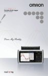
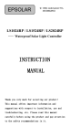
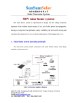
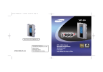
SL-02A Series Solar Power Intelligent Controller
INSTRUCTION MANUAL
VER1.1
Main features
1.
2.
3.
4.
5.
6.
7.
8.
9.
10.
Intelligent control is realized by using microprocessor and dedicated control calculation.
Four load working modes: Pure lighting control, lighting control & timing control, hand operation and
debug mode.
Scientific management of battery: as it is overcharged, the battery will get booster tension charge. As
a result compulsory maintenance is available for the battery. In normal working state, the direct charge
and floating charge are both available, so that the battery life-span is increased. Besides, the adoption
of high precision temperature compensation makes the charging more accurate.
Comparing with the charging loops using diodes, the one that adopts double MOS series circuit
control makes the voltage loss dropped by 50%. With the PWM fuzzy control in charging, the charge
efficiency is improved a lot.
LED screen shows the working state of solar battery, storage battery and load. LED shows the
adjusted parameter. In this way, users can learn the operation state in ream time. Besides, there are
various choices for parameter; users can select the proper working mode based on the different
conditions.
Various protections include over-charge, over-discharge and over-load, as well as unique electron
short circuit protection and connection-reverse protection. All the protections are harmless to any parts
and fuse. fuse only as the end protection of a controller itself to protect the amount of
internal short circuit damage. Non wire jumpers design improves the reliability and durability of the
products.
Industrial-grade chips and precision components are adopted for all the controls. Therefore, the
controller performs well in very low and high temperature, as well as humid environment. At the same
time, with the use of crystal timing control, the timing function of controller is much more reliable.
Using large-diameter wire terminal, can fix the wire which max size is 6mm²
parameter is set to power-down save function, the system model and control parameters, and other
important data are stored inside the chip, after power is not lost, to make the adjustment more
convenient, more reliable system.
Using 2 digital LEDs display and settings, one-button operation to complete all of the settings, intuitive
and easy to use..
Outside view of the controller (WINCONG)
System description (WINCONG)
Our controllers are specially designed for solar power DC supply system, solar power DC street lamp
system and mini solar power station system. Intelligent control is realized by using dedicated computer chips.
The controllers can be used in hard environment, since its adoption of technical grade chips. To the
controllers with 12V/24V automatic identification function, 12V and 24V Battery Auto sensing.
The short circuit, over-load, connection-reverse protection, as well as over-charge, over-discharge
protection are available. Besides, the complete indications are usable, including indications for states of
charge, storage battery and faults.
Through the computer chips, the controllers take samples from the parameters of storage battery voltage,
photo battery, discharge current and environment temperature, and then use the dedicated control mode
calculation to control the discharge rate and make it matched with the characters of storage battery, realize
the high accurate temperature compensation. PWM fuzzy charge mode and 7 phase voltage control are
available for the storage battery, so that storage battery is always in the perfect working state .The various
working modes of controllers can meet customers’ different requirements.
System main circuit diagram (WINCONG)
Installment and use (WINCONG)
1.
The controller must be well fixed. The dimension of the controller is
as following:
Outside dimension: 133×70×25 (mm); installation dimension:
126×50 (mm)
2.
Wire preparation: It is recommended to use multi-strand
insulated copper wire. Firstly, make sure the length of the
cord, secondly, ensure the installation location in the
circumstances, thirdly, try to minimize the connection length to reduce power consumption.
According to not more than 4A/mm ² in accordance with the current density of selected
cross-sectional area of copper wire, the controller side of the first strip 5mm of insulation
should be shucked off.
3.
Firstly, connect battery termination to the controller, and then connect to the other ends of
the battery. Pay attention to +, -, do not be reverse. If the connection is correct, (BAT)
indicator light should be lighted, according to buttons to check. Otherwise, the need to
check the connection.
4.
Photovoltaic cells’ wires connected, connect solar panels termination to the controller, and
then the other ends connected to solar panels. Pay attention to +, -, do not be reverse. If it is a sunny
day, (SUN) indicator light should be bright. Otherwise, there is need to check the connection.
5.
Load connected: connect the wire of load to the controller output, pay attention to +, -, do not be
reverse. Otherwise, it would burn appliances out.
6.
NOTE: Connecting photovoltaic cells and the load wires as followings:remain a curvature along the
wire to prevent the controller from rain water. (WINCONG)
WARNING: The combination of different error conditions may cause damage to the controller. Do not use
any other power supply instead of solar panels. ,otherwise may cause damage to the controller.
Operation procedure
A. Working state indication:
①. Solar panel state indication: the solar indicator light is flashes, as the input voltage of solar battery
panel reaches a certain point. The indicator light is on continually, as sunny and can charge the storage
battery, The indicator light is off, as disconnected solar cells or without enough sun, charge off;
②. Storage battery state and charge indication: when the storage battery is charging in
progress, , indicator light is on Green flashs;when the storage battery is fully charged, indicator light is
on Green continually; when the battery power is in the middle, indicator light is on red continually;when
the storage battery is over-discharged, the indicator light red flashs slowly and the load is off. In normal
working state, the indicator light is be bright.
③. Load indication: when the load is in normal working state, indicator light is on continually. when the
load is off state, indicator light is off continually. In over current or short circuit, the load is off at once and
the indicator light flashs. Then need to be adjusted. Then press wait 30 seconds, it will restart to work.
B. Setting methods:
To press the button for 3 seconds, the LED flashes and the system of the device is under mode of
regulation. After releasing the key, the data
in the LED changes along with every key-press till matches with the model designated by customers.
To finish the setting, please wait 30 seconds until the LED is OFF. Or just press the button for 3 seconds.
Check mode and output:when the LEDs is OFF, press the key for a Shorter time,the LEDs be
lighted and output is on,
C. Modes description
①.Lighting control: without sunshine the light intensity decreases to start point. Then the controller
recognizes the start signal after 30 seconds. Based on the parameter, the load is on. While under sunshine,
the light intensity increase to start point, and then the controller recognizes the close signal after 30 seconds.
The load is off.
② Time control: The starting procedure is the same with that of pure lighting control. Timing control
is dual period control; hence the double load can be regulated respectively. The load-on and load-off are
alternated till the load is off in daytime. The time for the load-on and load-off can be adjusted to realize the
different control effect. If the time for load-on is zero, the load will be off at night till the time for load-off is past.
If the time for load-off is zero, the control effect will be the same with that of pure lighting control.
③Manual mode: Regardless of the daytime or night, users can control the load-on and load-off by
key-press under this mode. This mode is used for some special load or Load ON all times(24 hours).
NOTE: when the storage battery is over-discharged and Load trouble ,the load of controller will be off.
④Test mode: this mode is designed for system regulation. It is almost the same with pure optical
mode except that the cancelation of 30 seconds delay (Please refer to pure lighting control). The load is on
with optical signal. In reverse, without optical signal, the load is off. This feature makes it easier to check the
system installation.
Working mode setting table
LED
DISPLAY
0
1
2
3
4
5
6
7
8
Work Mode
Dusk-to-Dawn, light is on all
light
1 hours light is turn on after
sundown
2 hours light is turn on after
sundown
3 hours light is turn on after
sundown
4 hours light is turn on after
sundown
5 hours light is turn on after
sundown
6 hours light is turn on after
sundown
7 hours light is turn on after
sundown
8 hours light is turn on after
sundown
LED
DISPLAY
Work Mode
9
9 hours light is turn on after sundown
10
10 hours light is turn on after sundown
11
11 hours light is turn on after sundown
12
12 hours light is turn on after sundown
13
13hours light is turn on after sundown
14
14 hours light is turn on after sundown
15
14 hours light is turn on after sundown
16
Manual mode
17
Test mode, lights on after it detects no
light, lights off after it detects light.
Parameter Description (WINCONG)
Type
rated charge
current
Rated load
current
Work Voltage
Over-load and short
circuit protection
No load losses
current
Charging circuit
voltage drop
Load circuit voltage
drop
Over voltage
protection
boost charge voltage
Direct charge
voltage
Float charge voltage
Charge recover
voltage
Over discharge
recover voltage
Lower voltage
indication
Over discharge
voltage
Temperature
compensation
Control method
Working
temperature
Circuit protection
SL02A-10A
SL02A-20A
SL02A-30A
10A
20A
30A
10A
20A
30A
□12V/24V Auto sensing/ auto switch
Over-load protection: when the current of controller is 1.25 times of the rated current, the
controller works for 30 seconds; 1.5 times of rated current, works for 5 seconds
Short circuit
protection: when the current of controller is more than or equal to 3 times of rated current, the
protection starts.
5mA-20mA(Only when digital LEDs be lighted)
<= 0.26V
<= 0.15V
14.8V;×2/24V;
14.6V; ×2/24V (time of duration: 10 minutes)
14.4V;×2/24V (time of duration: 10 minutes)
13.6V;×2/24V
13.2V;×2/24V
12.6V;×2/24V
12.0V;×2/24V
11.1V;×2/24V (no load)real-time modified voltage by the discharge rate
-4.0mV/℃/2V(boost voltage, direct charge, float charge and charge return voltage
compensation)
PWM Pulse-duration modulation charge mode
Industry stage: -35℃ to +55℃
Over-charge, over-discharge, short circuit and over-load
protection
Anti- connection-reverse protection for solar battery and storage battery.
All the protections are
harmless to any parts and
fuse of controller
FAQ
phenomenon
Under the sunshine, the indicator light
(NO.1) of solar panel is off
The indicator light (NO.2) of storage battery
is off
The indicator light (NO.2) of storage battery
Red flashes slowly without output.
The indicator light (NO.3) of load flashes
without output.
The indicator light (NO.3) is on continually
without output.
Others
solution
Please check the line connected to photocell and make sure the proper
connection
Please check whether the storage battery is well connected.
The storage battery is over-discharged. low voltage protection of battery
starts.
The load power is higher than the rated power or load is short circuit and
need to be adjusted. Then press wait 30 seconds, it will restart to work.
Please check whether the equipment which consumes power is well
connected.
Please check the connection,
Liability Exclusion
The manufacturer shall not be liable for damages, especially on the battery, caused by use other than
as intended or as mentionedin this manual or if the recommendations of the battery manufacturer are
neglected. The manufacturer shall not be liable for damages,unusual use, wrong installation, or bad system
design.
SL-02A micro computer solar charge controller
Complementary instruction for adjustable parameters of
upgraded version (VER1.2)
■ Upgrading instruction :
Upgrading SL-02A series of solar power controller has more Compatibility with a variety of storage
batteries such as opening lead-acid battery ,VRLA battery , gelled electrolyte (GEL)Battery, 3.2V*4
iron-phosphate-based lithium battery 3.2V*8 iron- phosphate-based lithium battery ,3.7V*3 lithium
battery,3.7V*6 lithium battery, and 3.7V*4 lithium battery. User can set the model of battery randomly .For
your further satisfaction, additional 4 groups of Voltage fine-adjustment parameters are available in the
controller, which allows user to conduct personalized adjustment of the parameters for the selected battery.
For example, we can set the battery parameters as the ones which help prolong the service life, also old
battery’s parameters can be adjusted to the favorable ones for long discharge time, parameters can be
changed into favorable ones according to various environments. And what’s more, the adjustment function
is up to the strict discharging requirements of some battery manufacturer, these characters enable user to
operate freely compared with the previous ones without this function. And voltage difference, resulting from
the wires connecting controller with storage batteries, can be offset by adjustment of controller
parameters .The controller has the parameters for adjusting controlling light sensitivity , by using the
parameters, users can control the time of lighting on in the evening or lighting off at dawn, or for street lamp
engineering, it can decrease the time difference result from the asynchronous on or off for multi- optical
control switches.
■ Parameters setting(WINCONG)
Digital
LED
display
parameters
default
Range of
Function
Function detail
setting
0-17
b1-b6
H0-H9,
H0.-H9.
o0-o9 ,
o0.-o9.
c0-c9 ,
c0.-c9.
L0-L9 ,
L0.-L9.
U1-U9
Work model
Setting
0=optical control(in the evening on or daytime off),1-15=turning on only at
night with duration 1-15hours, 16= for random turn on or off, 17=
debugging model(see previous instruction for more)
Selection of
storage battery
type
b1=opening battery ,b2=VRLA battery,b3=GEL battery,b4=3.2V*4 or
3.2V*8 LiFePO4 battery ,b5=3.7V*3 or 3.7V*6 lithium battery,b6=3.7V*4
lithium battery
Adjustment of
Maximum Charge
Voltage
H0 and H0.= no need adjustment , H1= Plus +0.1V, and the like
H9=Plus+0.9V; H1.=reduce -0.1V, and so on H9.=reduce -0.9V
Adjustment of
float Charge
Voltage
o0 and o0.= no need adjustment , o1= Plus +0.1V, and the like
o9=Plus+0.9V; o1.=reduce -0.1V, and so on o9.=reduce -0.9V
Adjustment of
Over discharge
recover voltage
c0 and c0.= no need adjustment , c1= Plus +0.1V, and the like
c9=Plus+0.9V; c1.=reduce -0.1V, and so on c9.=reduce -0.9V
Adjustment of
Over discharge
voltage
L0 and L0.= no need adjustment , L1= Plus +0.1V, and the like
L9=Plus+0.9V; L1.=reduce -0.1V, and so on L9.=reduce -0.9V
llight Sensitivity
adjustment of
optical control
Total 9 gears available for adjustment from U1-U9, U1= turning on or off in
very dark light .U9= turning on or off in very bright light.
■ Key setting operation:
When digital screen doesn’t work , please keep pressing 【KEY】( don’t stop pressing when number 0-17
shown on the screen) before the code of adjustment parameters shown on the screen , then adjustment can
be proceeded by pressing 【KEY】briefly. The number will be increased by one for each pressing, the cycle
will be automatically resume with minimum number when the number hits the maximum. After the
adjustment, we can enter into the second adjustment of parameters by keep pressing 【KEY】again . The
setting parameters can be preserved by pressing 【KEY】 until the light of number on the screen is off . Or
no operation of the controller for 30 seconds, the set parameter will be stored automatically.
Checking operation :when screen doesn’t work , keep pressing 【KEY】 ,the screen will show each code
in order, and loosen it when the light off . the code in order as below : 【Showing nothing】
【0】【b2】【H0】
【c0】【o0】【L0】【U4】【Showing nothing】. The whole process takes 10 seconds to keep pressing.
Please firstly choose battery type by setting code b1-b6.if you think the system default data is not okay,
please make further correction by the four parameters of H, o, c and L. For 12Voltage , its adjustment ranges
between ±0.9V,( for 24 Voltage the system will automatically multiply x2, and get ±1.8V). The system
default parameters for H, o, and c,L are Zero, which can not be revised.
■ Attentions(WINCONG)
1、 All final adjusted Voltage should always meet the law of 【Max Charging Voltage】>【 Floating
Charging Voltage】>【Over discharge recover Voltage 】>【Over discharge Voltage for Protective】
, or else the controller may not work properly. In addition, adjustment of these voltage parameters should be
conducted as per the charge acceptance capability of batteries, or improper adjustment may shorten the
battery service life or cause other serious consequences.
2、 We recommend that 12V battery should be connected to the solar power panels with Voltage rating
18V, and 36V solar power panes for 24V batteries, as the controller can recognize the two setting and
conduct the best operation automatically, but the two should not be mixed, if not, it may not work irregularly.
3. Some users, with no knowledge of these adjustable parameters and often utilization of
lead-acid storage batteries, can directly enter into previous operation setting and set 0-16 work
model, ignoring this manual .this is a simple way. Please don’t enter into the adjustment interface for
the parameters. If some parameters are revised without caution, please directly adjust back to the
【b2】【H0】【c0】【o0】【L0】【U4】 as per operational method .
default value 【0】