1
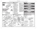
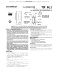
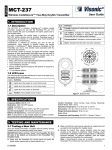
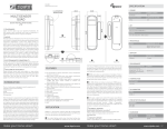
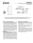
PRINTER’S INSTRUCTIONS:
INSTR,INSTL,WADWAZ-1; LINEAR P/N: P2067 X1; INK: BLACK; MATERIAL: 20# MEAD BOND; SIZE: 8.500” x 11.000”; SCALE: 1-1; PAGE 1 OF 2
WADWAZ-1
Radio Frequency Controlled
Wireless Door / Window Sensor
NOTE: This unit must be “included in the Network” only where it will be permanently installed. The proper operation of this node in the
mesh network is dependent on it knowing its location with respect to other nodes. You cannot “test bench” configure this module, then install.
For “Inclusion” to (adding to) a network:
Refer to your Controller operating instructions to add this module under the
command of the Wireless Controller.
WADWAZ-1 WIRELESS DOOR / WINDOW SENSOR
Linear’s family of Z-Wave™ certified wireless lighting controls (switches,
dimmers, outlets and plug-in modules) and Security devices (alert sounder,
passive infrared sensor and door/window transmitter) brings a new level of
intelligent wireless capability to commercial and residential environments.
1. Unscrew the screw fastening the rear cover and slide the rear cover down.
2. Insert a CR123A battery into the battery compartment and LED will start to flash
slowly, which means the sensor has not yet performed “inclusion” with the Controller.
3. Prepare the Controller to include a unit to the network by adding it to a group (method
of adding a node to the network). Refer to the Controller instructions.
4. If your Controller supports Network Wide Inclusion (NWI) locate the WADWAZ-1 near
the proposed installation location. If not skip to Step 6.
5. With your Controller in Inclusion mode, you should see an indication on your
Controller that the “device was included” in the network. It should display binary
switch / Linear. The LED will stop blinking. Skip to Step 9.
If the LED does not stop blinking, relocate the WADWAZ-1 to within 100 feet (line of
sight) of a Z-Wave device or your hub and repeat Step 5. If the LED continues to blink,
your Controller does not support NWI and continue with Step 6.
6. Place the WADWAZ-1 within 3 feet of the Controller.
7. With your Controller in Inclusion mode, depress the Program switch for 1 second
then release.
8. You should see an indication on your Controller that the “device was included” in the
network. It should display binary switch / Linear. The LED will stop blinking.
9. The device will appear in the list of Switches.
✓ NOTE: If you have trouble adding the WADWAZ-1 to a group it may be that the Home
ID and Node ID were not cleared from it after testing. You must first “RESET UNIT”
with your Controller to remove it from the network. Although adding it to a group
includes it in the network, removing it from a group does not remove it from the
network. If removed from a group, it functions as a repeater (only). “RESET UNIT”
removes it completely from the network.
The Z-Wave wireless protocol is an international wireless standard for remote
home automation, security and other applications. Embedded in each device,
the Z-Wave smart chip enables two-way RF communication among hundreds
of Z-Wave enabled devices, allowing products and services from multiple
manufacturers to work seamlessly.
Linear Z-Wave products are easy to install, and allow dealers to create an
integrated wireless network with nearly limitless expansion and interoperability
with security and health monitoring systems, energy management, home
entertainment, appliances, and more.
The WADWAZ-1 sensor monitors a door or window and sends Z-Wave
signals when the door is opened or closed. As part of a Z-Wave network,
the WADWAZ-1 will also act as a wireless repeater to insure that commands
intended for another device in the network are received. This is useful when
the device would otherwise be out of the radio range of the wireless controller.
For indoor use only. Retain instructions for future use.
INSTALLATION
If installing an entire Z-Wave system for the first time, refer to the installation
guide of the Z-Wave Interface Controller before installing the door/window
sensor.
For “Association” with another device:
The door/window sensor supports one association group with up to 5 nodes.
1. Set up the Z-Wave™ Interface Controller into “association” mode, and following its
instruction to associate the WADWAZ-1 with another device.
2. Open the door/window sensor case to “wake” the unit. In the Controller, associate the
sensor with the other device.
3. Close the door/window sensor case.
M
AL AGN
IGN ET
ME
NT
For “Exclusion” from (removing from) a network:
1. Set up the Z-Wave™ Interface Controller into “exclusion” mode, and following its
instruction to delete the WADWAZ-1 from the Controller.
2. Press the Program switch of WADWAZ-1 for 1 second and release to be excluded.
The LED light will flash continuously when the sensor is in the Exclusion condition.
3/4”
MAXIMUM
Magnet Gap Distance
1
PRINTER’S INSTRUCTIONS:
INSTR,INSTL,WADWAZ-1; LINEAR P/N: P2067 X1; INK: BLACK; MATERIAL: 20# MEAD BOND; SIZE: 8.500” x 11.000”; SCALE: 1-1; PAGE 2 OF 2
Mounting
INTEROPERABILITY WITH Z-WAVE DEVICES
1. Use the screws or adhesive tape to attach the rear cover to the frame along the
opening edge of the door or window.
2. Attach the magnet to the door or window adjacent to the marks on the sensor (see
illustration) BE SURE THE MAGNET IS NO FURTHER THAN 3/4” FROM THE
SENSOR WHEN THE DOOR OR WINDOW IS CLOSED.
A Z-Wave network can integrate devices of various classes, and these devices
can be made by different manufacturers, just as the WADWAZ-1 can be
incorporated into existing Z-Wave networks.
PACKAGE CONTENTS
•
•
•
•
•
•
WADWAZ-1 sensor with mounting bracket
Magnet with mounting bracket
Double-sided mounting tape
CR123A Battery
4x Screws for mounting
Installation Manual
REGULATORY INFORMATION
The WADWAZ-1 is certified to comply with applicable FCC and IC rules and regulations governing RF
and EMI emissions.
External Contact
To monitor an additional opening, an external normally closed switch contact
can be connected to the sensor’s external input terminals.
This device complies with Part 15 of the FCC Rules. Operation is subject to the following two conditions:
(1) This device may not cause harmful interference, and (2) This device must accept any interference
received, including interference received that may cause undesired operation.
1. To allow clearance for the external contact wires, break out the thin plastic wall of the
sensor case near the terminals.
2. Loosen the two terminal screws, insert the wires from the external contact into the two
terminals and tighten the two screws.
FCC Notice
This equipment has been tested and found to comply with the limits for a Class B digital device,
pursuant to Part 15 of the FCC Rules. These limits are designed to provide reasonable protection
against harmful interference in a residential installation.
This equipment generates, uses, and can radiate radio frequency energy and, if not installed and used
in accordance with the instructions may cause harmful interference to radio communications. However,
there is no guarantee that interference will not occur in a particular installation. If this equipment does
cause harmful interference to radio or television reception, which can be determined by turning the
equipment off and on, the user is encouraged to try to correct the interference by one or more of the
following measures:
• Reorient or relocate the receiving antenna.
• Increase the separation between the equipment and receiver
• Connect the equipment into an outlet on a circuit different from that to which the receiver is
connected
• Consult the dealer or an experienced radio/TV technician to help.
• Changes or modifications not expressly approved by the party responsible for compliance could
void the user’s authority to operate the equipment
Terminal Screws
IC Notice
This Class B digital apparatus complies with Canadian ICES-003
BASIC OPERATION
Cet appareil numérique de la classe B est conforme à la norme NMB-003 du Canada. Le présent
appareil est conforme aux CNR d’Industrie Canada applicables aux appareils radio exempts de
licence. L’exploitation est autorisée aux deux conditions suivantes : (1) l’appareil ne doit pas produire
de brouillage, et (2) l’utilisateur de l’appareil doit accepter tout brouillage radioélectrique subi, même si
le brouillage est susceptible d’en compromettre le fonctionnement.
• During normal operation with the door or window closed, the detector’s red
LED will be off.
• When the magnet moves away from the sensor as the door or window
opens, the sensor will send an alarm signal to any associated nodes and
the red LED will flash once.
• When the magnet moves back towards the sensor as the door or window
closes, the sensor will send a restore signal to any associated nodes and
the red LED will flash once.
• The sensor is equipped with a tamper switch. If the sensor is removed from
the mounting plate, it will send a tamper alarm signal and the red LED will
light constant.
See the table below for the alarm signal types and values.
Alarm Type
Alarm Event
Alarm Level
Internal Switch
Tamper Switch
External Switch
Internal Switch
Tamper Switch
External Switch
Internal Switch
Tamper Switch
External Switch
Cet appareil numérique de la classe B est conforme à la norme NMB-003 du Canada. Operation is
subject to the following two conditions: (1) this device may not cause interference, and (2) this device
must accept any interference, including interference that may cause undesired operation of the device.
WARRANTY
This Linear product is warranted against defects in material and workmanship for twelve (12) months.
This warranty extends only to wholesale customers who buy direct from Linear or through Linear’s
normal distribution channels. Linear does not warrant this product to consumers. Consumers should
inquire from their selling dealer as to the nature of the dealer’s warranty, if any. There are no obligations
or liabilities on the part of Linear Corporation for consequential damages arising out of or in
connection with use or performance of this product or other indirect damages with respect to
loss of property, revenue, or profit, or cost of removal, installation, or reinstallation. All implied
warranties, including implied warranties for merchantability and implied warranties for fitness, are valid
only until Warranty Expiration Date as labeled on the product. This Linear LLC Warranty is in lieu of
all other warranties express or implied. All products returned for warranty service require a Return
Product Authorization Number (RPA#). Contact Linear Returns at 1-855-546-3351 for an RPA# and
other important details.
0x07
0x02
0x03
0xFE
Close: 0x00; Open 0xFF
0xFF
Close: 0x00; Open 0xFF
IMPORTANT !!!
Linear radio controls provide a reliable communications link and fill an important need in portable
wireless signaling. However, there are some limitations which must be observed.
• For U.S. installations only: The radios are required to comply with FCC Rules and Regulations as
Part 15 devices. As such, they have limited transmitter power and therefore limited range.
• A receiver cannot respond to more than one transmitted signal at a time and may be blocked by
radio signals that occur on or near their operating frequencies, regardless of code settings.
SPECIFICATIONS
Battery
Frequency
Operating Temp
Repeater
Range
Copyright © 2014 Linear LLC
• Changes or modifications to the device may void FCC compliance.
• Infrequently used radio links should be tested regularly to protect against undetected interference
or fault.
CR123A Lithium Battery
908.42 MHz
5°F~140°F / -15°C~ 60°C
Yes
Up to 100 feet line of sight between the Z-Wave
Controller and/or the closest Z-Wave Repeater
• A general knowledge of radio and its vagaries should be gained prior to acting as a wholesale
distributor or dealer, and these facts should be communicated to the ultimate users.
2
P2067 X1