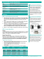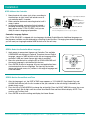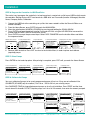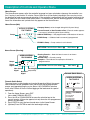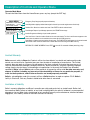
1
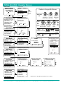
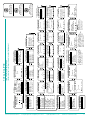
Total Eclipse Chemical Management System
Reference Manual Total Eclipse
Online and downloadable
Product Manuals and Quick Start
Guides are available at
www.HydroSystemsCo.com
Please check online for the latest
version of this Reference Manual.
!
WARNING:
The Total Eclipse controller
is intended to be installed by
experienced installers, in
accordance with all applicable
electrical and plumbing codes.
Preface
This manual has been written and illustrated to present the basic
installation, operation and servicing instructions of the Total Eclipse
Chemical Management System. Guidelines will be suggested in
reference to the preferred method of installation, however, the variety
of equipment and the surrounding environment will dictate the actual
installation of the Total Eclipse.
P/N 20-09130-00 Rev. E
© Hydro Systems Company, Inc. 2014
HydroSystemsCo.com
Toll Free: 1.800.543.7184
1
Table of Contents
1 Contoller Specifications........................................................................................................................ 3
2Installation.............................................................................................................................................. 3
3
Description of Controls and Operator Menu....................................................................................... 6
Warranty............................................................................................................................................ 7
4
Operator Menus..................................................................................................................................... 8
P/N 20-09130-00 Rev. E
© Hydro Systems Company, Inc. 2014
HydroSystemsCo.com
Toll Free: 1.800.543.7184
2
TOTAL ECLIPSE Controller Specifications
Size5'25" W x 4.0" H x 2.5" D (13.4 cm W x 10.2 cm H x 6.4 cm D)
Weight
0.65 lb. (0.30 kg)
Power Rating
SELV — Power source is pumpstand
Data Input Field Size 15 characters maximum input for custom names
Pump Capacity
99.99 oz. (2999 ml.) 8 pump (with 3 amount settings per pump) maximum
Environmental
IP Rating – 44
Pollution Category – 2
Installation Category – II
Temperature
10° to 49° C (50° to 120° F) maximum
Humidity
95% relative humidity, maximum
Indoor Installation
Approved for indoor use only. Must not be installed outdoors.
Altitude
Install at or below 6,500 ft.
Installation
STEP 1: Install the Machine Interface (MI)
1. Route MI signal wires through 1/2 inch knock-out on washer (within
the wiring area). Secure MI to washer with lock nut (provided). Signal
wires are to be connected according to instructions in step two
below.
2. Plug J2 cable into MI. Bundle excess J2 cable outside washer and
connect other end to J2 connector on rear of Controller.
3. Connect J1 cable from pump module to J1 connector on Controller.
The maximum length of J cables should not exceed 75 ft. (22.9 m.)
unless using a break out box and hard wiring. Contact Hydro
Systems for additional cables, a coupler or detailed instructions.
4. Secure J1 and J2 cables to controller tie-down posts with tie wraps.
!
WARNING/ADVERTENCIA:
Disconnect all power to the pumpstand during
installation, service, and/or any time pump
cabinet is opened. The TOTAL ECLIPSE
should be installed by a qualified technician
only, in accordance with all applicable
electrical and plumbing codes.
Desconecte toda la corriente eléctrica al
dosificador durante la instalación, servicio y / o
siempre que se abra el gabinete de la bomba.
El equipo TOTAL ECLIPSE debe ser instalado
sólo por técnicos calificados y de acuerdo con
todas las normas de plomería y electricidad
que apliquen.
!
WARNING/ADVERTENCIA:
Keep MI and communication J cables away
from high voltage wires and relays. NEVER
parallel the J cables with high voltage lines.
Mantenga M.I. y los cables J de comunicación
separados de los cables de alta tensión y
relés. NUNCA instale el cable J paralelo con
las líneas de alta tensión.
STEP 2: Connect Signal Wires
Voltage
The Machine Interface will work with any signal voltage between 24 – 240VAC
or 22 – 24VDC. With DC signals, polarity must be observed. Common is
negative. The signals should be positive voltages.
Supply Trigger Wiring
Identify the washer supply signals. In Standard or Group Mode of
Operation, connect Machine Interface wires to machine supply signals
using appropriate terminal connectors. Use table below for reference.
(Do not use this table for Event or Occurrence Modes; see Manual.)
Trigger Signal Wiring Notes: • If one or more pump signals are not used, they do not need to be
connected. Cap any wires that are not used.
• If you are triggering more than one pump from a single signal,
connect all MI signal wires for those pumps
to that signal.
• If washer has a single common, wire nut all commons together.
Trigger
Supply
Signal
Signal
Common
Connect to:
Stand ard (US) Group (EU)
Signal 1
Signal 2
Signal 3
Signal 4
Signal 5
Signal 6
Black Wire
Brown Wire
Red Wire
Orange Wire
Yellow Wire
Blue Wire
White/Black
White/Brown
White/Red
White/Orange
White/Yellow
White/Blue
Pump 1
Pump 2
Pump 3
Pump 4
Pump 5
Pump 6
P/N 20-09130-00 Rev. E
© Hydro Systems Company, Inc. 2014
!
WARNING/ADVERTENCIA:
Always verify all voltage sources with a meter.
Electrical wiring connections for supply
triggers are to be done inside the junction box.
Siempre verifique la alimentación de corriente
con un voltímetro. Las conexiones eléctricas
a los disparadores de suministro (supply)
deben hacerse dentro del recinto donde se
encuentran los suministros (supply).
Group 1
Group 1
Group 2
Group 2
Group 3
Group 4
HydroSystemsCo.com
Toll Free: 1.800.543.7184
3
Installation
STEP 3: Mount the Controller
1. Mount bracket with velcro-style strips, according to
the directions at right. Install wall board screws or
nuts and allen bolts, if needed.
2. Slide controller down onto mounting bracket until it
snaps in place.
3. Install pump module and make all electrical and
plumbing connections for the system, but DO NOT
apply power to the TOTAL ECLIPSE until you are
ready to select a language of operation.
1 Attach Velcro-s
Velcro-style Strips and Mount
2 (Optional)
Install Wall Board
Screws or Masonry
Nuts & Allen Bolts
Mounting
M
o
Bracket
3 With J1 and J2
2 cables
de
e Contro
oller
connected, slide
Controller
u it snaps into
o place.
onto mounting bracket until
Controller Language Options
Each TOTAL ECLIPSE is shipped with two languages installed: English/Spanish. Additional languages, as
they become available, may be obtained by contacting Hydro Systems. If changing from default languages,
you will need your language-enabled USB flash drive for the next step.
STEP 4: Select the Controller Menu Language
1. Apply power to pumpstand & power-up Controller. Two available
LANGUAGES are displayed. (Optional) To replace the non-English
language, connect a USB flash drive with the new language to the
controller’s USB port (under flap on right side of controller).
2. Move the selection box by using the UP or DOWN ARROWS until
the correct language is contained within the box.
3. Press ENTER to select a language. All menu and application items
are translated into the new language. Text input by the installer
(pump and formula name, etc.) remains in the original language and
is not translated.
EXIT
UP
LEFT
ENTER
RIGHT
DOWN
TOTAL ECLIPSE Keypad
STEP 5: Set the Current Date and Time
1. After the language is set, the DATE & TIME menu appears as YYYY-MM-DD (Year-Month-Day) and
HH:MM (Hour:Minute) with the first number of the year selected as the active digit, indicated by the
double-arrow cursor.
2. Press the UP or DOWN ARROW to change the active digit. Press the RIGHT ARROW to move the cursor
to the next digit. Set all digits until the current Year-Month-Date and Hour:Minute display. NOTE: Time
must be set in military time.
3. Press ENTER to save the setting and display the Home Screen.
P/N 20-09130-00 Rev. E
© Hydro Systems Company, Inc. 2014
HydroSystemsCo.com
Toll Free: 1.800.543.7184
4
Installation
STEP 6: Program the Controller via USB Flash Drive
The easiest way to program the controller is to load a previously created set-up file from a USB flash drive onto
the controller. Settings that are NOT transferred via a USB drive are: Passwords (Installer & Manager); Machine
Name; Company Name; Calibration.
1. Connect the USB flash drive containing set up files that were created in either the Formula Editor or on
another controller.
2. From the Home Screen, press ENTER to launch the MAIN MENU.
3. Move the selection box to INSTALLER MENU by pressing and holding the DOWN ARROW.
4. Press ENTER and input the default Installer Password of 01234, using the UP ARROW to increment the
number and the RIGHT ARROW to move the cursor.
5. Press ENTER to accept the password input. Select DATA TRANSFER from the Installer Menu and follow
the sequence below:
1. Select Installer Menu
2. Input Password
3. Select Data Transfer
NOVA CONTROLS
F01
MAIN MENU
INSTL PASSWORD
INSTALLER MENU
01234
EMERGENCY PUMP STOP
LOAD SIZE: 200 LB
USER PRIME PUMPS
USER MANUAL FLUSH
MANAGER REPORTS
INSTALLER MENU
OK
EXIT
4. Display Files on USB
DATA TRANSFER
WRITE REPORTS
READ SETUP
WRITE SETUP
UPDATE FIRMWARE
WRITE ACTIVITY LOG
OK
EXIT
INSTALLER SERVICE
INITIAL SYSTEM SETUP
PROGRAM FORMULAS
DATA TRANSFER
SET UNITS OF MEASURE
5. Send File to Controller
SETUP FILE
POG Restaurants
BLS Services
Eclipse Hotel
Hospital Settings
International Hotel
AA School District
Default Home Screen
6. Remove USB flash drive. Press EXIT to return to the Installer Menu, in order to prime and calibrate
(required) pumps.
STEP 7: Prime Pumps
Press ENTER to start and stop prime. After priming is complete, press EXIT until you reach the Home Screen.
1. Select Installer Service
2. Select Service Pumps
3. Select Prime Pump
5. Select Pump to Prime
INSTALLER MENU
INSTALLER SERVICE
SERVICE PUMPS
SET PRIME PUMP
INSTALLER SERVICE
INITIAL SYSTEM SETUP
PROGRAM FORMULAS
DATA TRANSFER
SET UNITS OF MEASURE
SERVICE PUMPS
VIEW LOAD WEIGHT
VIEW AMOUNT PUMPED
CLEAR DATA LOG
PRIME PUMP
PUMP CALIBRATION
NAME PUMPS
ENTER PRODUCT COSTS
DATE TUBE CHANGED
P2
P1
P2
P3
P4
P5
P6
6. Start/Stop Prime
PRIME
START/STOP
EXIT
STEP 8: Calibrate the Pumps
You must calibrate all pumps to be used; programmed pumps will not run if they are not calibrated. Use
CALIBRATE (VOLUME) only for medium (12 or 18 oz. / 355 or 532 ml. per minute) pumps.
Use CALIBRATE (TIME) for large displacement pumps or for a flush installation. Press START and the timer
counts down 20 seconds. DO NOT stop the pump; run it for a full 20 seconds, then enter the amount pumped.
2. Select Service Pumps
INSTALLER MENU
INSTALLER SERVICE
INSTALLER SERVICE
INITIAL SYSTEM SETUP
PROGRAM FORMULAS
DATA TRANSFER
SET UNITS OF MEASURE
SERVICE PUMPS
VIEW LOAD WEIGHT
VIEW AMOUNT PUMPED
CLEAR DATA LOG
3. Select Pump Calibration
SERVICE PUMPS
PRIME PUMP
PUMP CALIBRATION
NAME PUMPS
ENTER PRODUCT COSTS
DATE TUBE CHANGED
4. Select Calibration Method
PUMP CALIBRATION
VIEW CALIBRATION
CALIBRATE (TIME)
CALIBRATE (VOLUME)
5. Select Pump to Calibrate
CALIBRATE (TIME)
5. Select Pump to Calibrate
CALIBRATE (VOL.)
P1
P2
P3
P4
P5
P6
P/N 20-09130-00 Rev. E
© Hydro Systems Company, Inc. 2014
HydroSystemsCo.com
CALIBRATE
P2
P2
STOP PUMP AT 8 OZ
WARNING! PLACE
CONTAINER AT OUTPUT!
START/STOP
EXIT
6. Run Pump Full 20 Seconds
P1
P2
P3
P4
P5
P6
6. Collect 8 oz [250 ml]
CALIBRATE
20.0
0.0
WARNING! PLACE
CONTAINER AT OUTPUT!
START/STOP
EXIT
6.1 Input Amount Collected
DISPENSED VOLUME
ENTER AMOUNT PUMPED
00.0 OZ
1. Select Installer Service
OK
Toll Free: 1.800.543.7184
EXIT
5
Description of Controls and Operator Menu
Home Screen
The Home Screen appears after the controller language has been selected or whenever the controller is active. If no key is pressed for 15 minutes, Power Save turns off the display’s backlight. Press any key to turn
the backlight on and resume normal operation. If the controller is powered off, the last formula selected is the
active formula on the Home Screen when power is turned back on. See the following graphic for an explanation of the information and symbols that may appear on the Home Screen.
Home Screen (Idle)
HYDRO SYSTEMS
F03 TOWELS
Pumps
1 2 _
5 6
_ _ _ _ _ _
Company Name (can be changed during Initial System Setup)
Current Formula (or Next Formula to Run) (Formula number appears if no name is input during Initial System Setup)
NON-ACTIVE Pump — Not programmed or calibrated; not in formula
READY Pump — Calibrated and has amount(s) programmed
ERROR in Pump — Pump number is not in formula
HOT KEYS: Formula Quick-Select
Main Menu
Home Screen (Running)
HYDRO SYSTEMS
F03 RUNNING
Pumps
1 2 _
Trigger
Signals
_ 2 _ 4 _ _
5 6
Running Formula — Note that formula name is not shown
when running
ACTIVE Pump — Currently running
Complete — Box indicates that pump has finished its
programmed run
HOT KEYS: Formula Quick-Select
Non-Active
Receiving Signal
(Unqualified)
Signal
Qualified
Signal
1. From the Home Screen, press EXIT
(also called FORMULA SELECT).
2. Press the UP or DOWN ARROW to move the selection box to the
correct formula. All formulas appear, but only formulas with programmed
pumps are selectable.
3. Press ENTER to start the formula and return to the Home Screen.
4. (Optional) Press ENTER to reach the load weight setting.
© Hydro Systems Company, Inc. 2014
Main Menu
Formula Quick-Select
Formula Quick-Select
To prevent errors in data logging or chemical dispensing: Select the correct
formula before washer operation starts and be sure that all programmed
pumps are triggered during the cycle. (Note: A NO CHEMICAL selection
exists after Formula 20 that will allow logging of the load count for special
operations).
P/N 20-09130-00 Rev. E
HydroSystemsCo.com
HYDRO SYSTEMS
F03 TOWELS
1 2 3 4 5 6
_ _ 3 _ _ _
SELECT FORMULA
F01 PADS
F02 CURTAINS
F03 TOWELS
F04 BED LINEN
F05 BLANKETS
F06 TABLE LINEN
Press to
Move
Selection
Box
Press to
Select
Formula
Toll Free: 1.800.543.7184
6
Description of Controls and Operator Menu
Operator Main Menu
To reach the Main Menu from the Home Screen, press any key (except the EXIT key).
MAIN MENU
EMERGENCY PUMP STOP
LOAD WEIGHT
275 LB
USER PRIME PUMPS
USER MANUAL FLUSH
MANAGER REPORTS
INSTALLER MENU
VIEW LOAD COUNT
PUMP STATUS
Emergency Pump Stop (stops all pumps and formulas).
Load Weight Menu (displays default load weight for formula. Input actual weight at start of each load).
Selection Box—Move box to select menu item. Press ENTER to launch selected menu.
Print Manager Reports—Input Manager password, then FROM/TO date range.
Installer Programs and Settings—Input installer password.
View Load Count—View the number of loads run for each wash formula. The View Load Count text appears on the
screen when the selection box is moved down the screen with the DOWN arrow key.
Pump Status—View the status and settings of each pump. The PUMP STATUS text appears on the screen beneath
VIEW LOAD COUNT when the selection box is moved down the screen using the DOWN arrow key.
RETURN TO HOME SCREEN: Press EXIT
or wait 15 seconds without pressing a key.
Limited Warranty
Seller warrants solely to Buyer the Products will be free from defects in material and workmanship under
normal use and service for a period of one year from the date of completion of manufacture. This limited
warranty does not apply to (a) hoses; (b) and products that have a normal life shorter than one year; or (c)
failure in performance or damage caused by chemicals, abrasive materials, corrosion, lightning, improper
voltage supply, physical abuse, mishandling or misapplication. In the event the Products are altered or
repaired by Buyer without Seller’s prior written approval, all warranties will be void. No other warranty, oral,
express or implied, including any warranty of merchantablilty or fitness for any particular purpose, is
made for these products, and all other warranties are hereby expressly excluded.
Seller’s sole obligation under this warranty will be, at Seller’s option, to repair or replace F.O.B. Seller’s
facility in Cincinnati, Ohio any Products found to be other than as warranted.
Limitation of Liability
Seller’s warranty obligations and Buyer’s remedies are solely and exclusively as stated herein. Seller shall
have no other liability, direct or indirect, of any kind, including liability for special, incidental, or consequential
damages or for any other claims for damage or loss resulting from any cause whatsoever, whether based on
negligence, strict liability, breach of contract or breach of warranty.
P/N 20-09130-00 Rev. E
© Hydro Systems Company, Inc. 2014
HydroSystemsCo.com
Toll Free: 1.800.543.7184
7
TOTAL ECLIPSE Operator Menus
Home Screen
Formula Select
SELECT FORMULA
NOVA
HYDROCONTROLS
SYSTEMS
F01 PADS
F02 CURTAINS
F03 TOWELS
F04 BED LINEN
F05 BLANKETS
F06 TABLE LINEN
F02 CURTAINS
123X56788
_ 2 _ _ _ _
Main Menu (Emergency Pump Stop)
=
SELECTION
BOX
Emergency Pump Stop
EMERGENCY STOP
MAIN MENU
EMERGENCY PUMP STOP
LOAD WEIGHT
275 LB
USER PRIME PUMPS
USER MANUAL FLUSH
MANAGER REPORTS
INSTALLER MENU
VIEW LOAD COUNT
STOP ALL PUMPS
AND FORMULAS
EDIT
VALUE
EXIT
220 LB
(SINGLE LOAD)
OK
EXIT
P1 PRE-WASH
P2 DETERGENT
P3 LIQUID BLEACH
P4 BLEACH ALTERNATIVE
P5 SOUR/CONDITI
P6 ENZYME LIFT
Main Menu (User Manual Flush)
Trigger Signal Icon
Pump Icon
Installer Menu Access
PRIME
MAIN MENU
P3 LIQUID BLEACH
EMERGENCY PUMP STOP LOAD SIZE
180 LB
USER PRIME PUMPS
USER MANUAL FLUSH
MANAGER REPORTS
INSTALLER MENU
EXIT
INSTL PASSWORD
Start/Stop Flush (if flush enabled)
01234
EXIT
Input Manager Password
MGR PASSWORD
Set Date for Report Header
Set “SAVE AS” File Name & Date
REPORT DATE
REPORT NAME
00-00-00
0123
WASH23 12-10-08
OK
EXIT
EXIT
OK
START/STOP
EXIT
INSERT USB DRIVE
OK
EXIT
View Load Count
TOTAL LOAD COUNT
F01 PADS
F02 CURTAINS
F03 TOWELS
F04 BED LINEN
F05 BLANKETS
F06 TABLE LINEN
0
0
0
0
0
0
VIEW LOAD COUNT
P/N 20-09130-00 Rev. E
Pumping &
Flushing
Flushing
OK
Main Menu (Manager Reports)
MAIN MENU
Pumping
(Flush Off)
MANUAL FLUSH
EMERGENCY PUMP STOP
LOAD SIZE
275 LB
USER PRIME PUMPS
USER MANUAL FLUSH
MANAGER REPORTS
INSTALLER MENU
VIEW LOAD COUNT
EXIT
Only
Steady On
Start / Stop Prime Pump
START/STOP
ENTER
Saves
& Exits
MAIN MENU
EMERGENCY PUMP STOP
LOAD SIZE
275 LB
USER PRIME PUMPS
USER MANUAL FLUSH
MANAGER REPORTS
INSTALLER MENU
Select Pump to Prime (if enabled)
F02 FO3
FO4 More Items
HOME
SCREEN
SET PRIME PUMP
EMERGENCY PUMP STOP LOAD SIZE
275 LB
USER PRIME PUMPS
USER MANUAL FLUSH
MANAGER REPORTS
INSTALLER MENU
VIEW LOAD COUNT
Main Menu (View Load Count)
UP/DOWN
LEFT/RIGHT
Arrows Input Arrows Move
Value (0-9, A-Z)
Cursor
MENU
SYMBOLS
Main Menu (User Prime Pump)
EMERGENCY PUMP STOP
LOAD SIZE
275 LB
USER PRIME PUMPS
USER MANUAL FLUSH
MANAGER REPORTS
INSTALLER MENU
VIEW LOAD COUNT
or
LOAD WEIGHT
EMERGENCY PUMP STOP LOAD SIZE
275 LB
USER PRIME PUMPS
USER MANUAL FLUSH
MANAGER REPORTS
INSTALLER MENU
VIEW LOAD COUNT
ENTER also
Starts/Stops
Action
350 LBS =
Input Actual Load Weight
MAIN MENU
MAIN MENU
UP/DOWN
ENTER Key
Arrows Move
Launches
Selection Box Menu Item
STOP
Main Menu (Load Size)
MAIN MENU
Guide to Keypad & Menus
Select
& Return
to Home
Screen
© Hydro Systems Company, Inc. 2014
Display returns to Main Menu after data transfer is complete.
HydroSystemsCo.com
Toll Free: 1.800.543.7184
8
_ _
0
0
0
0
0
0
P1
P1A
P1B
P1C
SAE / IMPERIAL (LB/OZ)
METRIC (KG/ML)
UNITS-MEASURE
OK
2009-02-08
Toll Free: 1.800.543.7184
5. Set Units of Measure
EXIT
REPORTEXIT
DATE
TO: OK
2009-01-08
FROM:
HI CAP WASH
INSERT USB DRIVE
OK
EXIT
SETUP FILE
POG Restaurants
BLS Services
Eclipse Hotel
Hospital Settings
International Hotel
AA School District
EXIT
OK
OK
EXIT
P2 DETERGENT
P3 LIQUID BLEACH
P4 BLEACH ALT
P5 SOUR/CONDITI
P6 ENZYME LIFT
P7
EXIT
HH:MM
17:06
OK
NEW NAME
EXIT
3.4 Edit Formula Name
NAME F01
OK
2 009- 07- 28
EXIT
EXIT
2.13 Set Date & Time
DATE & TIME
OK
YYYY-MM-DD
3.3 Set Count Pump
F01 COUNT PUMP
OK
HYDRO
NOVA SYSTEMS
2.6 Edit Company Name
COMPANY NAME
50
2.12 Adjust Screen Contrast
LCD CONTRAST
OK
HOUSEKEEPING 01
2.5 Edit Machine Name
MACHINE NAME
EXIT
HOTEL 17
SETUP NAME
Overwrites file of same
name on USB flash drive.
Does not transfer passwords,
machine name, company
name or calibrations.
INSERT USB DRIVE
OK
EXIT
EXIT
DO NOT attempt firmware
update unless you have your
PC Update Program and
proper computer cable.
WARNING!
OK
STOP!!! DO NOT
PROCEED WITHOUT
PC UPDATE PROGRAM!
UPDATE FIRMWARE
4.3 Write Setup - Name File being sent
(from Controller to USB flash drive) 4.4 Update Firmware
EXIT
0 0 0 LB
3.2 Default Load Weight
F01 LOAD WEIGHT
OK
DISABLE
ENABLE
LIMITED 30 SEC
EXIT
2.11 User Prime Enable
SET USER PRIME
OK
Overwrites ALL settings &
formulas, except passwords,
machine name, company
name & calibrations.
REPORT NAME
ZERO DATA LOG
WARNING! ALL LOGS
(LOADS & VOLUMES)
WILL BE CLEARED!
HOTEL ECLIPSE - 67
4.2 Read Setup - Select File to
load from USB to Controller
TO TEST
0 0 0 SEC
00.00 OZ
00.00 OZ
00.00 OZ
F01 P1
DELAY
AMOUNT
AMOUNT
AMOUNT
REPORT DATE
WRITE REPORTS
READ SETUP
WRITE SETUP
UPDATE FIRMWARE
WRITE ACTIVITY LOG
EXIT
3.1.3 Pump Settings
(0 = OFF)
OK
0
2.10 Auto-Formula Select
AFS TRIGGER
STANDARD
RELAY
EVENT
GROUP
OCCURRENCE
0.0
0.0
0.0
0.0
0.0
0.0
1.4 Clear Data Log
2.4 Edit Account Name
ACCOUNT NAME
P1 PRE-WASH
P2 DETERGENT
P3 LIQUID BLEAC
P4 BLEACH ALT
P5 SOUR/CONDITI
P6 ENZYME LIFT
PUMPED (GAL)
1.3 View Amount Pumped
INSTALLER SERVICE
INITIAL SYSTEM SETUP
PROGRAM FORMULAS
DATA TRANSFER
SET UNITS OF MEASURE
INSTALLER MENU
Installer Top Level Menu
2.3 Set-up Operating Mode
OPERATION MODE
DATA TRANSFER
P1 PRE-WASH
P2 DETERGENT
P3 LIQUID BLEACH
P4 BLEACH ALT
P5 SOUR/CONDITI
P6 ENZYME LIFT
3.1.2 Add Pumps to Formula
F01 PUMPS
2 SECONDS
10 SECONDS
20 SECONDS
30 SECONDS
60 SECONDS
90 SECONDS
EXIT
0123
2.9 Set Trigger Signal Filter
TRIGGER FILTER
OK
2.2 Edit Manager Password
MGR PASSWORD
F01 PADS
F02 CURTAINS
F03 TOWELS
F04 BED LINEN
F05 BLANKETS
F06 TABLE LINEN
TOTAL WEIGHT
4.1.2 Set “SAVE AS” File Name
PUMP SETTINGS
SET DEFAULT WEIGHT
SET COUNT PUMP
EDIT NAME
CLEAR FORMULA
EXIT
3.1 Set Formula
F01
OK
(0 = OFF)
9 0 MINUTES
EXIT
1.2 View Load Weight
OK
4.1 Set Report “FROM / TO” Date
EXIT
2.8 Set Cycle Time Limit
CYCLE TIME LIMIT
OK
01234
2.1 Edit Installer Password
INST PASSWORD
01234
INSTL PASSWORD
Input Installer Password
4. Upload / Download Data
F01
F02 CURTAINS
F03 TOWELS
F04 BED LINEN
F05 BLANKETS
F06 TABLE LINEN
PROGRAM FORMULAS
3. Formula Programming
SET PUMP INTERFACE
SET CYCLE TIME
SIGNAL FILTER TIME
SET AFS TRIGGER
SET USER PRIME
SET LCD CONTRAST
SET DATE AND TIME
CLEAR SETTINGS
VIEW SOFTWARE ID
EDIT INST PASSWORD
EDIT MGR PASSWORD
OPERATION MODE
EDIT ACCOUNT NAME
EDIT MACHINE NAME
EDIT COMPANY NAME
SYSTEM SETUP
2. Initial System Setup
PRIME PUMP
PUMP CALIBRATION
NAME PUMPS
ENTER PRODUCT COSTS
DATE TUBE CHANGED
SERVICE PUMPS
SERVICE PUMPS
VIEW LOAD WEIGHT
VIEW AMOUNT PUMPED
CLEAR DATA LOG
1.1 Pump Maintenance /Service
INSTALLER SERVICE
EMERGENCY PUMP STOP LOAD SIZE:
175 LB
USER PRIME PUMPS
USER MANUAL FLUSH
MANAGER REPORTS
INSTALLER MENUS
MAIN MENU
Main Menu
1. Service / Routine Maintenance
_ 2 _ 4 _ _
1 2 3
NOVA
HYDRO
SYSTEMS
F03 TOWELS
Home Screen
(factory default settings shown in selection boxes)
Top Level Installer Menus
TOTAL ECLIPSE
HydroSystemsCo.com
© Hydro Systems Company, Inc. 2014
EXIT
EXIT
ABBA
REPORT NAME
4.5 Diagnostic Activity Log
OK
WARNING! FORMULA
WILL BE CLEARED TO
FACTORY DEFAULT!
3.5 Clear Formula
CLEAR F01
OK
WARNING! ALL SETUPS
WILL BE CLEARED TO
FACTORY DEFAULTS!
2.14 Clear Controller Settings
CLEAR SETTINGS
NON-FLUSH
ECLIPSE FLUSH P. I.
ORION I I FLUSH P. I.
8-PUMP FLUSH P. I.
2.7 Set Pump Interface
(and Flush Time, if needed)
PUMP INTERFACE
Enter / Save Key
- Launches selected menu
- Saves new input & exits
Right / Left Arrow
During input, moves the
cursor ( ) to the next digit
Up / Down Arrow
- Moves Selection Box
- Changes digit value
INSERT USB DRIVE
OK
EXIT
P/N 20-09130-00 Rev. E
9