1
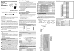
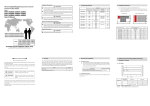
Mitsubishi General-Purpose Programmable Controller Renewal Tool Conversion Adapter Model ERNT-AQT62DA User’s Manual ERNT-AQT62DA Model ERNT-AQT62DA 50CM-D180031-C(1007)MEE HEAD OFFICE:NIHONJISHO-DAIICHI BLDG.1-13-5,KUDANKITA CHIYODA-KU,TOKYO 102-0073,JAPAN NAGOYA ENGINEERING OFFICE:139 SHIMOYASHIKICHO-SHIMOYASHIKI,KASUGAI,AICHI 486-0906,JAPAN SAFETY PRECAUTIONS (Always read these precautions prior to use.) Before using this product, please read this manual carefully and pay full attention to safety to ensure that the product is used correctly. The precautions presented in this manual are concerned with this product only. For Programmable Controller system safety precautions, refer to the user’s manual of the MELSEC-Q seriesCPU module to be used. In this manual, the safety precautions are ranked as “DANGER” and “CAUTION.” DANGER Indicates that incorrect handling may cause hazardous CAUTION Indicates that incorrect handling may cause hazardous conditions, resulting in death or severe injury. conditions, resulting in medium or minor injury and/or property damage. Note that failure to observe the CAUTION level instructions may lead to a serious consequence according to the circumstances. Always follow the precautions of both levels because they are important to personal safety. Please keep this manual in an easy-to-access location for future reference, and be sure to provide the manual to the end user. [Precautions: Prior to Use] CAUTION When replacing the MELSEC-A series with the MELSEC-Q series, be sure to refer to the various MELSEC-Q series module manuals to check the differences in performance, functionality, CPU input/output signals, buffer memory addresses, and the like. In addition, we recommend that you also refer to the document L(NA)08045-D, “Guidelines: Replacing MELSEC-A/QnA (Large-Size) Series with Q Series (Intelligent Function Module).” [Installation Precautions] CAUTION Use the conversion adapter and conversion adapter anchor base in an environment of the general specifications defined in the MELSEC-Q series CPU module user’s manual. Failure to do so could lead to electric shock, fire, malfunction or product failure or deterioration. Do not come in direct contact with the conductive area of the conversion adapter. Doing so could lead to system malfunction or failure. Fully secure the conversion adapter and conversion adapter anchor base using the installation screws, and tighten the installation screws securely within the specified torque range. Failure to do so could cause the conversion adapter and anchor base to fall, resulting in conversion adapter and conversion adapter anchor base damage. Be sure to confirm that the MELSEC-Q series and conversion adapter combination is correct. Use of a different combination may result in module damage A-1 [Wiring Precautions] DANGER Be sure to shut off all phases of the external power supply before performing installation or wiring work. Failure to do so could result in electric shock or product damage. If you want to energize and run the unit after completing the installation and wiring work, be sure to close the terminal block cover attached to the MELSEC-A series terminal block. Failure to do so could result in electric shock. CAUTION Properly wire the conversion adapter after verifying the specifications and terminal layout of the module to be used. Connecting a power supply with a different rating or improper wiring could lead to fire or product failure. Securely tighten the conversion adapter installation screws, conversion adapter anchor base installation screws and MELSEC-A series terminal block installation screws within the specified torque range. A loose screw may result in a short circuit, fire or malfunction. An excessively tightened screw may result in screw or conversion adapter damage, causing the conversion adapter to fall, a short circuit or product malfunction. Do not allow foreign matter such as cuttings or wiring shavings to enter the conversion adapter or module. Doing so could lead to fire, failure or malfunction. [Startup and Maintenance Precautions] DANGER Do not touch the terminals during energization. Doing so could result in electric shock or malfunction. Be sure to shut off all phases of the external power supply before cleaning and retightening terminal screws. Failure to do so results in the risk of electric shock. Excessively tightened screws could result in conversion adapter and module damage, causing the conversion adapter to fall, a short circuit, or product malfunction. CAUTION Do not disassemble or modify the conversion adapter. Doing so could lead to failure, malfunction, injury or fire. The conversion adapter case is made of resin. Do not drop or apply excessive impact to the case. Doing so could lead to conversion adapter damage. [Disposal Precautions] CAUTION When disposing of the product, treat it as industrial waste. A-2 REVISIONS *The manual number is given on the bottom right of the front cover. Print Date *Manual Number Revision October 2008 50CM-D180031-A First Edition April 2010 Partially corrected 50CM-D180031-B EMC AND LOW VOLTAGE DIRECTIVES July 2010 50CM-D180031-C Partially corrected SAFETY PRECAUTIONS This manual confers no industrial property rights or any rights of any other kind, nor does it confer any patent licenses. Mitsubishi Electric Engineering cannot be held responsible for any problems involving industrial property rights which may occur as a result of using the contents noted in this manual. ã 2008-2010 MITSUBISHI ELECTRIC ENGINEERING COMPANY LIMITED EMC AND LOW VOLTAGE DIRECTIVES Compliance to the EMC Directive, which is one of the EU Directives, has been a legal obligation for the products sold in European countries since 1996 as well as the Low Voltage Directive since 1997. Manufacturers who recognize their products are compliant to the EMC and Low Voltage Directives are required to declare that print a "CE mark" on their products. Authorized representative in Europe Authorized representative in Europe is shown below. Name: Mitsubishi Electric Europe B.V. (EMC C.C. Division) Address: Gothaer strasse 8, 40880 Ratingen, Germany A-3 CONTENTS SAFETY PRECAUTION ·······························································································································A-1 REVISIONS ··················································································································································A-3 EMC AND LOW VOLTAGE DIRECTIVES ···································································································A-3 CONTENTS ····················································································································································· 1 1. Overview··············································································································································· 1 2. Conversion Adapter Product Specifications························································································· 2 3. Products Required by the Conversion Adapter···················································································· 5 4. Mounting and Installation······················································································································ 6 5. Part Names and Installation Method ···································································································· 7 6. Conversion Adapter Anchor Base Installation Method ········································································ 8 7. External Dimensions··························································································································· 11 1. Overview This manual describes the Mitsubishi general-purpose Programmable Controller renewal tool conversion adapter (ERNT-AQT62DA) and the conversion adapter anchor base (sold separately; ERNT-AQF12/-AQF8/-AQF5/-AQF3) that secures the bottom of the conversion adapter. The conversion adapter is a product that converts the differences in MELSEC-A series and MELSEC-Q series pin assignments. When replacing the MELSEC-A series with the MELSEC-Q series, be sure to refer to the various MELSEC-Q series module manuals to check the differences in performance, functionality, CPU input/output signals, buffer memory addresses, and the like. In addition, we recommend that you also refer to the document L(NA)08045-D, “Guidelines: Replacing MELSEC-A/QnA (Large-Size) Series with Q Series (Intelligent Function Module).” Once you have opened the packaging, verify that it contains the following products. Product Quantity Conversion adapter 1 Mounting bracket 1 Mounting bracket fixing screw (M3.5 x 6) 2 1 2. Conversion Adapter Product Specifications Conversion A Series Module No. of analog Q Series Module Conversion Adapter Adapter Model Model output Points Model Weight (g) ERNT-AQT62DA A62DA 2 Q62DAN 130 A62DA-S1 A Series Terminal Block TB1 TB2 TB3 TB4 TB5 TB6 TB7 TB8 TB9 TB10 TB11 TB12 TB13 TB14 TB15 TB16 TB17 TB18 TB19 TB20 Terminal No. TB1 TB2 TB3 TB4 TB5 TB6 TB7 TB8 TB9 TB10 TB11 TB12 TB13 TB14 TB15 TB16 TB17 TB18 TB19 TB20 Signal Name Terminal No. TEST TEST OPEN DC24 V+ DC24 VOPEN OPEN V+ C VH I+ 1 IOPEN V+ C VH I+ 2 IOPEN OPEN OPEN OPEN(FG) When grounding FG, perform wiring to TB20. TB1 TB2 TB3 TB4 TB5 TB6 TB7 TB8 TB9 TB10 TB11 TB12 TB13 TB14 TB15 TB16 TB17 TB18 V+ CH1 COM I+ OPEN V+ CH2 COM I+ OPEN OPEN OPEN OPEN OPEN OPEN OPEN OPEN 24V 24G FG Conversion Adapter 2 Signal Name Q Series Terminal Block TB2 TB4 TB6 TB8 TB10 TB12 TB14 TB16 TB18 TB1 TB3 TB5 TB7 TB9 TB11 TB13 TB15 TB17 Module Specification Comparison Chart Voltage Analog output Current Analog Output Voltage Current 10V 5V 20mA 0V 4mA -5V -12mA -10V - Digital Input Input/Output characteristics Maximum resolution 2000 1000 0 -1000 -2000 A62DA-S1 Q62DAN 16-bit signed binary (0 to 4000) 16-bit signed binary (Normal resolution mode: -4096 to 4095, High resolution mode: -12288 to 12287, -16384 to 16383) 0 to 10VDC (External load resistance value: 500Ω to 1MΏ) 4 to 20mA DC (External load resistance value: 0Ω to 600Ώ) Output Range 0 to 10V 0 to 5V 0 to 20mA 0 4000 0 5V or 20mA 1V or 4mA Output Range 1 to 0 to 0 to Overall accuracy Maximum conversion speed Absolute Voltage maximum Current No. of analog output points Between output terminal and PLC power supply Isolation method Between channels Between external power supply and analog output No. of occupied points Connected terminal block Current consumption External Voltage power Current ±1.0% 5V 25°C (within ± 0.5%) 0 to 55°C (within ± 1%) ±25 mV ±50 mV Analog Output Range 0V or 0mA Voltage 1 to 5V: 1mV(1/4000) 0 to 5V:1.25mV(1/4000) 0 to 10V:2.5mV(1/4000) Current 4 to 20mA:4μA(1/4000) 0 to 20mA:5μA(1/4000) Temperature Range 0 to 20mA DC (External load resistance value: 0Ω to 600Ώ) Digital Input Analog Output 4000 10V 0 0V 5V or 4000 20mA 1 to 5V 4 to 20mA Voltage: 5mV(1/2000) Current: 20μA(1/1000) -10 to 10VDC (External load resistance value: 1KΩ to 1MΏ) 4 to 0 to 5V 10V 20mA 20mA ±25 ±50 ±0.1 ±0.1 mV mV mA mA ±50 ±100 ±0.2 ±0.2 mV mV mA mA Voltage Digital input A62DA 16-bit signed binary (Voltage: -2000 to 2000, Current: -1000 to 1000) 16-bit signed binary -10 to 0 to 10VDC (External load resistance value: 500Ω to 1MΏ) 4 to 20mA DC (External load resistance value: 0Ω to 600Ώ) Current Item Normal Resolution Mode High Resolution Mode Digital Maximum Digital Input Value Resolution Input Value 0 to 0 to 1.25m 0 to 4000 1 to 1.0mV -16000 to 2.5mV -10 to -4000 to 16000 -12000 to 4000 User range 0.75m 12000 setting 0 to 5μA 0 to 4000 0 to 12000 4 to 4μA -12000 to User range -4000 to 1.5μA 4000 12000 setting 0.625m 0.333m 1.66μA 1.33μA 0.83μA 25 ± 5°C ambient temperature: Within ± 0.1% (Voltage: ± 10mV, Current: ± 20µA) 0 to 55°C ambient temperature: Within ± 0.3% (Voltage: ± 30mV, Current: ± 60µA) Within 15ms /2 channels (Same time for one channel) ±12V 28mA 2 channels/module Within 15ms /2 channels (Same time for one channel) 0 to 12V 0 to 28mA 2 channels/module ±12V 21mA 2 channels/module Photocoupler isolation Photocoupler isolation Photocoupler isolation Non-isolated Non-isolated Non-isolated - - Transformer isolation 32 points 20-point terminal block 0.60A 21.6 to 26.4VDC 0.35A 32 points 20-point terminal block 0.60A 21.6 to 26.4VDC 0.35A 16 points 18-point terminal block 0.33A 24VDC + 20%, - 15% 0.15A 3 Maximum Resolution 0.416m 0.333m 80µs/channel Note: 1. When grounding the FG terminal (terminal number TB18) of the Q62DAN side, use terminal number TB20 on the MELSEC-A series side. Use this when you want to ground the FG terminal. 2. TB17 TB18 TB19 TB20 OPEN OPEN OPEN OPEN(FG) Program changes (changes to the number of occupied input/output points, input/output signals, and buffer memory addresses) are required. 3. For detailed and general specifications not stated in the Specification Comparison Chart, refer to the user’s manual of the module used. In addition, we recommend that you also refer to the document L(NA)08045-D, “Guidelines: Replacing MELSEC-A/QnA (Large-Size) Series with Q Series (Intelligent Function Module).” For those sections in which the MELSEC-A series specifications and MELSEC-Q series specification differ, specification restrictions may apply upon replacement. Check the specifications of the connected devices. 4 3. Products Required by the Conversion Adapter (1) Conversion Adapter Anchor Base (Sold Separately) The conversion adapter anchor base secures the bottom of the conversion adapter and is required for conversion adapter use. One anchor base is required per base. Specifications Conversion Adapter Anchor Base Model (2) Type Weight (g) ERNT-AQF12 12-slot conversion adapter anchor base 590 ERNT-AQF8 8-slot conversion adapter anchor base 410 ERNT-AQF5 5-slot conversion adapter anchor base 275 ERNT-AQF3 3-slot conversion adapter anchor base 185 Base Adapter (Sold Separately) The base adapter enables MELSEC-Q series installation using the installation holes of the MELSEC-A series base unit. (Additional hole machining not required) Specifications MELSEC-Q Series Installable Conversion Adapter Anchor Base Compliant Module Base Adapter Model MELSEC-A Series Compliant Module ERNT-AQB38 A38B Q312B ERNT-AQF12 A38HB Q38B ERNT-AQF8 ERNT-AQB68 A68B Q612B Q68B ERNT-AQB58 A58B Q68B ERNT-AQF8 870 ERNT-AQB35 A35B Q38B ERNT-AQF8 795 Q35B ERNT-AQF5 ERNT-AQB65 A65B Weight (g) 970 930 790 Q68B Q65B Q55B ERNT-AQB55 A55B Q65B ERNT-AQF5 655 ERNT-AQF3 675 Q55B ERNT-AQB32 A32B Q33B ERNT-AQB62 A62B ERNT-AQB52 A52B Q63B Q52B Q52B 5 650 505 4. Mounting and Installation 4.1 Handling Precautions (1) (2) (3) (4) Do not touch the terminals during energization. Doing so could result in electric shock or malfunction. Do not disassemble or modify the conversion adapter. Doing so could result in failure, malfunction, injury or fire. Do not come in direct contact with the conductive area of the conversion adapter. Doing so could result in system malfunction or failure. Fully secure the conversion adapter and conversion adapter anchor base using the installation screws, and securely tighten the screws within the specified torque range. Failure to do so could cause the conversion adapter and anchor base to fall, resulting in conversion adapter and conversion adapter anchor base damage. 4.2 Use Precautions Item Module width dimension Use Precautions Because the module width decreases (from 37.5mm to 27.4mm), the wiring area decreases. Verification prior to installation is required. MELSEC-Q series module I/O MELSEC-A series module 27.4 37.5 Depth The depth increases. Verification prior to installation is required. Q series module + A series module Renewal tool Conversion adapter Base adapter Conversion adapter anchor base 130 166.2 36.2mmUP(24.4mm) The value in parentheses is the dimension when the base adapter is not used. 4.3 Installation Environment For details of the installation environment, refer to the user’s manual of the MELSEC-Q series CPU module to be used. 6 5. Part Names and Installation Method Q series module Mounting bracket (conversion adapter accessory) M3.5 x 6 (conversion adapter accessory) M3.5 x 6 (conversion adapter accessory) 2 Conversion adapter installation screw M3 x 30 3 MELSEC-A series terminal block installation screw (M4) 5 2 6 5 Conversion adapter anchor base Conversion adapter MELSEC-A series terminal block Conversion adapter bottom installation screw M3 x 45 4 Conversion adapter anchor base installation screw M4 x 8 (conversion adapter anchor base accessory) 6 5.1 Installation Method [1] [2] [3] [4] [5] [6] Secure the conversion adapter anchor base to the base adapter or control panel using the conversion adapter anchor base installation screws (M4 ´ 8) provided as an accessory. (Two end locations) Secure the mounting bracket to the Q series module using the mounting bracket fixing screws [M3.5 ´ 6 (conversion adapter accessory); two upper/lower locations]. Mount the conversion adapter onto the mounting bracket. Secure the conversion adapter using the conversion adapter bottom installation screw (M3 ´ 45; 1 location). Secure the conversion adapter using the conversion adapter installation screws (M3 ´ 30; 2 locations). Secure the MELSEC-A series terminal block to the conversion adapter using the terminal block installation screws (M4; two upper/lower locations). 5.2 Tightening Torque Tighten the module installation screws to the specified torque below. An inappropriate tightening torque could cause the product to fall or result in a short circuit, product failure or malfunction. Screw Location Tightening Torque Range Conversion adapter anchor base installation screw (M4 screw) 139 to 189N・cm Mounting bracket fixing screw (M3.5 screw) 68 to 92 N・cm Conversion adapter bottom installation screw (M3 screw) 43 to 57 N・cm Conversion adapter installation screw (M3 screw) MELSEC-A series terminal block installation screw (M4 screw) 7 102 to 138 N・cm 6. Conversion Adapter Anchor Base Installation Method To use the conversion adapter, a conversion adapter anchor base (ERNT-AQF12/-AQF8/-AQF5/-AQF3) is required. Q Base Unit Conversion Adapter Anchor Base Q312B Q38B Q35B Q33B Q612B Q68B Q65B Q63B Q55B Q52B ERNT-AQF12 ◎ × × × ◎ × × × × × ERNT-AQF8 ○ ◎ × × ○ ◎ × × × × ERNT-AQF5 × ○ ◎ × × ○ ◎ × ◎ × ERNT-AQF3 × × × ◎ × × × ◎ × ◎ ◎: Applicable ○: Applicable (with some restrictions*1) ×: Not applicable *1: There are certain slots in which the conversion adapter cannot be installed. For example, the conversion adapter cannot be installed in Slots 8 to 11 (4 slots) of the Q base unit when Q312B (Q base unit) is used with ERNT-AQF8 (conversion adapter anchor base). The machining of screw holes (M4 ´ 2 locations) used to install the conversion adapter anchor base, such as described below, is required when a base adapter (sold separately) is not used. (1) With Main Base Unit Q312B, Q38B, Q35B or Q33B Machine screw holes (M4 x 2 locations) in these locations for conversion adapter anchor base installation. 118.5±0.2 CPU ERNT-AQF** 94.8±0.2 A±0.2 8 Conversion Adapter Anchor Base A ERNT-AQF12 321.2 ERNT-AQF8 210 ERNT-AQF5 126.6 ERNT-AQF3 71 With Extension Base Unit Q612B, Q68B Q65B or Q63B Machine screw holes (M4 x 2 locations) in these locations for conversion adapter anchor base installation. 118.5±0.2 (2) ERNT-AQF** 87.4±0.2 With Extension Base Unit Q55B Machine screw holes (M4 x 2 locations) in these locations for conversion adapter anchor base installation. 118.5±0.2 (3) A±0.2 ERNT-AQF5 126.6±0.2 31.8±0.2 9 Conversion Adapter Anchor Base A ERNT-AQF12 321.2 ERNT-AQF8 210 ERNT-AQF5 126.6 ERNT-AQF3 71 With Extension Base Unit Q52B Machine screw holes (M4 x 2 locations) in these locations for conversion adapter anchor base installation. 118.5±0.2 (4) ERNT-AQF3 4±0.2 71±0.2 Tips Use of a base adapter (sold separately) eliminates the need for additional screw hole machining on the control panel. (A base adapter is a product that enables MELSEC-Q series installation using the MELSEC-A series installation holes.) 10 7. External Dimensions 7.1 Conversion Adapter 204 92 Mounting bracket 25.7 41.9 18.9 27.4 7.2 Conversion Adapter Anchor Base A B 20 27.8 98 C Model ERNT-AQF12 ERNT-AQF8 ERNT-AQF5 ERNT-AQF3 A 335.8 224.6 141.2 85.6 11 B 305.8 194.6 111.2 55.6 C 321.2 210 126.6 71 Product Warranty Details Please confirm the following product warranty details prior to product use. Gratis Warranty Terms and Gratis Warranty Range If any fault or defect (hereinafter referred to as “Failure”) attributable to Mitsubishi Electric Engineering Company Limited (hereinafter referred to as “MEE”) should occur within the gratis warranty period, MEE shall repair the product free of charge via the distributor from whom you made your purchase. Gratis Warranty Period The gratis warranty period of this product shall be one (1) year from the date of purchase or delivery to the designated place. Note that after manufacture and shipment from MEE, the maximum distribution period shall be six (6) months, and the gratis warranty period after manufacturing shall be limited to eighteen (18) months. In addition, the gratis warranty period for repaired products shall not exceed the gratis warranty period established prior to repair. Gratis Warranty Range The gratis warranty range shall be limited to normal use based on the usage conditions, methods and environment, etc., defined by the terms and precautions, etc., given in the instruction manual, user’s manual and caution labels on the product. Warranty Period after Discontinuation of Production (1) (2) MEE shall offer product repair services (fee applied) for seven (7) years after production of the product has been discontinued. Discontinuation of production shall be reported via distributors. Product supply (including spare parts) is not possible after production has been discontinued. Exclusion of Opportunity Loss and Secondary Loss from Warranty Liability Regardless of the gratis warranty period, MEE shall not be liable for compensation for damages arising from causes not attributable to MEE, opportunity losses or lost profits incurred by the user due to Failures of MEE products, damages or secondary damages arising from special circumstances, whether foreseen or unforeseen by MEE, compensation for accidents, compensation for damages to products other than MEE products, or compensation for other work carried out by the user. Changes in Product Specifications The specifications given in the catalogs, manuals and technical documents are subject to change without notice. This document is a new publication, effective July 2010. Specifications are subject to change without notice. The standard price does not include consumption tax. Please note that consumption tax will be added at the time of purchase. This manual was printed on recycled paper. Developed July 2010 50CM-D180031-C