1
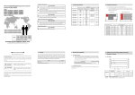
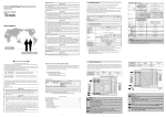
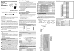
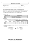
Mitsubishi General-Purpose Programmable Logic
Controller Renewal Tool Base Adapter
Model
ERNT-AQB38/-AQB35/-AQB32
ERNT-AQB68/-AQB65/-AQB62
ERNT-AQB58/-AQB55/-AQB52
User’s Manual
ERNT-AQB38/-AQB35/-AQB32
ERNT-AQB68/-AQB65/-AQB62
ERNT-AQB58/-AQB55/-AQB52
ERNT-AQB38/-AQB35/-AQB32
Model ERNT-AQB68/-AQB65/-AQB62
ERNT-AQB58/-AQB55/-AQB52
50EM8557-A(0510)MEE
SAFETY PRECAUTIONS
(Always read these precautions prior to use.)
Before using this product, please read this manual carefully and pay full attention to safety to ensure that
the product is used correctly.
The precautions presented in this manual are concerned with this product only. For PLC system safety
precautions, refer to the user’s manual of the CPU module to be used.
In this manual, the safety precautions are ranked as “DANGER” and “CAUTION.”
DANGER
CAUTION
Indicates that incorrect handling may cause hazardous
conditions, resulting in death or severe injury.
Indicates that incorrect handling may cause hazardous
conditions, resulting in medium or minor injury and/or property
damage.
Note that failure to observe the
CAUTION level instructions may lead to a serious consequence
according to the circumstances. Always follow the precautions of both levels because they are important
to personal safety.
Please keep this manual in an easy-to-access location for future reference, and be sure to provide the
manual to the end user.
Installation Precautions
CAUTION
Use the base adapter in an environment of the general specifications defined in the CPU module
user’s manual. Failure to do so could lead to electric shock, fire, malfunction or product failure or
deterioration.
Fully secure the base adapter, Q base unit and conversion adapter anchor base using the
installation screws, and tighten the installation screws securely within the specified torque range.
Failure to do so could cause the product to fall, resulting in damage.
DANGER
Be sure to shut off all phases of the external power supply before performing installation work.
Failure to do so could result in electric shock or product damage.
Startup and Maintenance Precautions
DANGER
Be sure to shut off all phases of the external power supply before cleaning and retightening the
installation screws. Failure to do so could lead to electric shock. Excessively tightened screws
could result in damage, causing the product to fall, a short circuit or product malfunction.
Disposal Precautions
DANGER
When disposing of the product, treat it as industrial waste.
1. Overview
This manual describes the Mitsubishi general-purpose PLC renewal tool base adapter (ERNT-AQB38,
ERNT-AQB35,
ERTN-AQB32,
ERNT-AQB68,
ERNT-AQB65,
ERNT-AQB62,
ERNT-AQB58,
ERNT-AQB55, ERNT-AQB52). The base adapter is a product that enables MELSEC-Q series
installation using the MELSEC-A series installation holes. (Additional hole machining not required)
Once you have opened the packaging, verify that it contains the following products.
Product
Quantity
Base adapter
1
Q base unit installation screws (M4 x 8)
4
2. Product Specifications
Specifications
Base Adapter Model
MELSEC-A Series
Compatible Module
MELSEC-Q Series
Compatible Module
Installable
Conversion Adapter
Anchor Base
Weight
(g)
ERNT-AQB38
A38B
Q312B
ERNT-AQF12
970
A38HB
Q38B
ERNT-AQF8
A68B
Q612B
ERNT-AQB68
930
Q68B
ERNT-AQB58
A58B
Q68B
ERNT-AQF8
870
ERNT-AQB35
A35B
Q38B
ERNT-AQF8
795
Q35B
ERNT-AQF5
ERNT-AQB65
A65B
Q68B
790
Q65B Q55B
ERNT-AQB55
A55B
Q65B
ERNT-AQF5
655
ERNT-AQF3
675
Q55B
ERNT-AQB32
A32B
Q33B
ERNT-AQB62
A62B
Q63B
650
Q52B
ERNT-AQB52
A52B
Q52B
505
3. Mounting and Installation
3.1 Handling Precautions
(1)
Do not drop or apply heavy impact to the base adapter. Doing so could result in damage.
(2)
Fully secure the Q base unit and conversion adapter anchor base using the installation
screws, and securely tighten the screws within the specified torque range. Loose screws
could cause a short circuit, fire or malfunction.
Screw Location
Q base unit installation screw (M4 screw)
Tightening Torque Range
139 to 189N・cm
Conversion adapter anchor base installation screw (M4 screw)
3.2 Installation Environment
For details of the installation environment, refer to the user’s manual of the CPU module to be used.
4. Installation Dimensions
(1)
The width dimension is smaller than that of the MELSEC-A series.
(2)
The base adapter installation holes (4 locations) have the same installation dimensions as
those of the MELSEC-A series base unit. There is no need for additional screw hole
machining on the control panel.
(Reference) MELSEC-A Series
(25)
(15)
MELSEC-Q Series
200
250
I/O
I/O
I/O
I/O
I/O
I/O
I/O
I/O
CPU
C
(C)
B
A
25
25
電源
200
240
CPU
C
(C)
B
A
Base Adapter Model
A
B
C
MELSEC-A Series Base
Unit Model
A
B
C
ERNT-AQB38
480
460
10
A38B, A38HB
480
460
10
ERNT-AQB68
466
446
10
A68B
466
446
10
ERNT-AQB58
411
391
10
A58B
411
391
10
ERNT-AQB35
382
362
10
A35B
382
362
10
ERNT-AQB65
352
332
10
A65B
352
332
10
ERNT-AQB55
297
277
10
A55B
297
277
10
ERNT-AQB32
247
227
10
A32B
247
227
10
ERNT-AQB62
238
218
10
A62B
238
218
10
ERNT-AQB52
183
163
10
A52B
183
163
10
5. Q Base Unit and Conversion Adapter Anchor Base
Installation Locations
5.1 ERNT-AQB38
A
B
a
Conversion Adapter
Anchor Base
b
ERNT-AQF12
ERNT-AQF8
A
A
a
a
Q Base Unit
Q312B
Q38B
Combination not possible
Upper half :
Q base unit installation location
Lower half :
Conversion adapter anchor base screw tightening location
B
b
5.2 ERNT-AQB68
A
B
a
Conversion Adapter
Anchor Base
b
ERNT-AQF12
ERNT-AQF8
A
A
a
a
Q Base Unit
Q612B
Q68B
Combination not possible
Upper half :
Q base unit installation location
Lower half :
Conversion adapter anchor base screw tightening location
B
b
5.3 ERNT-AQB58
Q base unit Q68B
installation location
Conversion adapter anchor base
ERNT-AQF8 installation location
5.4 ERNT-AQB35
A
B
a
Conversion Adapter
Anchor Base
b
ERNT-AQF8
ERNT-AQF5
A
A
a
a
Q Base Unit
Q38B
Q35B
Combination not possible
Upper half :
Q base unit installation location
Lower half :
Conversion adapter anchor base screw tightening location
B
b
5.5 ERNT-AQB65
A
B
C
a
Conversion Adapter
Anchor Base
b
ERNT-AQF8
ERNT-AQF5
A
A
a
a
Q Base Unit
Q68B
Q65B
Combination not possible
Q55B
Combination not possible
Upper half :
Q base unit installation location
Lower half :
Conversion adapter anchor base screw tightening location
B
b
C
b
5.6 ERNT-AQB55
A
B
a
Conversion Adapter
Anchor Base
ERNT-AQF5
Q Base Unit
A
Q65B
a
B
Q55B
a
Upper half :
Q base unit installation location
Lower half :
Conversion adapter anchor base screw tightening location
5.7 ERNT-AQB32
Q base unit Q33B
installation location
Conversion adapter anchor base
ERNT-AQF3 installation location
5.8 ERNT-AQB62
A
B
a
Conversion Adapter
Anchor Base
ERNT-AQF3
Q Base Unit
A
Q63B
a
B
Q52B
Upper half :
Lower half
a
Q base unit installation location
:
Conversion adapter anchor base screw tightening location
5.9 ERNT-AQB52
Q base unit Q52B
installation location
Conversion adapter anchor base
ERNT-AQF3 installation location
240
50
200
(15)
6. External Dimensions
B
11.8
A
11.8
Base Adapter Model
A
B
ERNT-AQB38
480
460
ERNT-AQB68
466
446
ERNT-AQB58
411
391
ERNT-AQB35
382
362
ERNT-AQB65
352
332
ERNT-AQB55
297
277
ERNT-AQB32
247
227
ERNT-AQB62
238
218
ERNT-AQB52
183
163
Product Warranty Details
Please confirm the following product warranty details prior to product use.
Gratis Warranty Terms and Gratis Warranty Range
If any fault or defect (hereinafter referred to as “Failure”) attributable to Mitsubishi Electric Engineering
Company Limited (hereinafter referred to as “MEE”) should occur within the gratis warranty period, MEE shall
repair the product free of charge via the distributor from whom you made your purchase.
Gratis Warranty Period
The gratis warranty period of this product shall be one (1) year from the date of purchase or delivery to
the designated place.
Note that after manufacture and shipment from MEE, the maximum distribution period shall be six (6)
months, and the gratis warranty period after manufacturing shall be limited to eighteen (18) months.
In addition, the gratis warranty period for repaired products shall not exceed the gratis warranty period
established prior to repair.
Gratis Warranty Range
The gratis warranty range shall be limited to normal use based on the usage conditions, methods and
environment, etc., defined by the terms and precautions, etc., given in the instruction manual, user’s
manual and caution labels on the product.
Warranty Period after Discontinuation of Production
(1)
(2)
MEE shall offer product repair services (fee applied) for seven (7) years after production of the product
has been discontinued. Discontinuation of production shall be reported via distributors.
Product supply (including spare parts) is not possible after production has been discontinued.
Exclusion of Opportunity Loss and Secondary Loss from Warranty Liability
Regardless of the gratis warranty period, MEE shall not be liable for compensation for damages arising from
causes not attributable to MEE, opportunity losses or lost profits incurred by the user due to Failures of MEE
products, damages or secondary damages arising from special circumstances, whether foreseen or
unforeseen by MEE, compensation for accidents, compensation for damages to products other than MEE
products, or compensation for other work carried out by the user.
Changes in Product Specifications
The specifications given in the catalogs, manuals and technical documents are subject to change without
notice.
This document is a new publication, effective October 2005. Specifications are subject to change without
notice. The standard price does not include consumption tax. Please note that consumption tax will be added
at the time of purchase. This manual was printed on recycled paper.
Developed October 2005
50EM8557-A