1
R20UT3410EJ0100
Rev.1.00
Mar 23, 2015
Applilet3 for RL78 V1.07.00
Release Note
Contents
1.
Introduction ........................................................................................................................................ 3
2.
Target Devices .................................................................................................................................. 4
3.
Operating Environment ................................................................................................................... 10
4.
Changes .......................................................................................................................................... 11
4.1
Details of Changes ................................................................................................................. 13
4.1.1 Output code changes of real-time clock ............................................................................ 13
4.1.2 Output code changes of serial array unit ............................................................................ 14
4.1.3 Addition of PMC register setup ........................................................................................... 16
4.1.4 Output code changes of the receiving function of UARTn ................................................. 16
4.1.5 Control correction of a competition pin ............................................................................... 16
4.1.6 GUI correction of an A/D converter .................................................................................... 17
4.1.7 Changes of square wave output of a timer ........................................................................ 17
4.1.8 Changes of the TTL check box of a port ........................................................................... 17
4.1.9 Changes of PIOR setup ..................................................................................................... 17
4.1.10 Changes of TAU1 setup .................................................................................................. 17
4.1.11 Changes of UART2 setup ................................................................................................ 18
4.1.12 Changes of key interrupt function..................................................................................... 18
4.1.13 Changes of Simplified I2C ................................................................................................ 18
4.1.14 Additional function generation file mode .......................................................................... 19
4.1.15 Changes of hdwinit() function ........................................................................................... 20
4.1.16 Changes of API about Simplified I2C by SAU ................................................................... 21
4.1.17 Changes of the timer RD and the timer RJ0, and new restriction ..................................... 22
4.1.18 Changes of input pulse interval measurement of TAU...................................................... 24
4.1.19 Changes the notation of a power supply ........................................................................... 24
4.1.20 It corresponds to renewal of device user's manual ........................................................... 24
4.1.21 Additional of the GCC code output .................................................................................... 25
4.1.22 Changes the Key Input Interrupt Setting ........................................................................... 25
4.1.23 Changes the A/D Converter Operation Setting ................................................................. 25
4.1.24 Changes the clock frequency of operation ........................................................................ 25
4.1.25 Changes the watch error correction of real-time clock ...................................................... 25
4.1.26 Changes of CPU and peripheral clock (fCLK) in the clock generator settings ................. 25
4.1.27 Changes for Using the Remote Control Carrier Wave Mask Signal ................................. 25
4.1.28 Changes the Case When Ports that Are Not Available in the MCU Are Displayed .......... 26
4.1.29 Changes Setting of Port1 .................................................................................................. 26
4.1.30 Changes setting of interval timer ....................................................................................... 26
4.1.31 Changes for CPU stack pointer monitor function .............................................................. 26
4.1.32 Changes for comparator setting ........................................................................................ 26
4.1.33 Changes for DTC setting ................................................................................................... 26
4.1.34 Changes for the voltage detection circuit to “Interrupt Mode” ........................................... 26
R20UT3410EJ0100 Rev1.00
Mar 23,2015
Page 1 of 32
Applilet3 for RL78 V1.07.00
5.
Release Note
Cautions .......................................................................................................................................... 27
5.1
Cautions List ........................................................................................................................... 27
5.2
Cautions Details ..................................................................................................................... 28
5.2.1 Cautions of the LIN-bus function of UART0,UART2,UART3,UART6 or UARTF .............. 28
5.2.2 Cautions of the operation for slave transmission of serial interface IICA or IIC0 .............. 28
5.2.3 Cautions of extension code, multimaster,wakeup function of serial interface IICA or IIC028
5.2.4 Restrictions of High-speed on-chip oscillator frequency select register ............................. 29
5.2.5 Restriction of a serial array unit .......................................................................................... 29
5.2.6 Cautions of PORT .............................................................................................................. 29
5.2.7 Cautions of a setup of a real-time clock ............................................................................ 29
5.2.8 Cautions when using a DTC function ................................................................................. 30
5.2.9 Cautions of initial function of an A/D converter ................................................................. 30
5.2.10 Cautions of initial function at the time of setting up UART transmission.......................... 31
5.2.11 Cautions of Complementary assistant PWM mode of TimerRD ...................................... 31
5.2.12 Restrictions of internal low-speed or internal high-speed oscillator trimming ................... 31
5.2.13 Cautions of Safety Functions ............................................................................................ 31
5.2.14 Cautions of file merge ...................................................................................................... 31
5.2.15 Cautions of timer array unit input clock sauce .................................................................. 31
5.2.16 Cautions of a high-speed on-chip oscillator ...................................................................... 32
5.2.17 Cautions of Voltage Detector function ............................................................................... 32
R20UT3410EJ0100 Rev1.00
Mar 23,2015
Page 2 of 32
Applilet3 for RL78 V1.07.00
Release Note
1. Introduction
Applilet3 for RL78 is a software tool to generate device driver code for on-chip peripherals. It generates
device driver codes using user settings through GUI. Initialize code and API functions are provided.
R20UT3410EJ0100 Rev1.00
Mar 23,2015
Page 3 of 32
Applilet3 for RL78 V1.07.00
Release Note
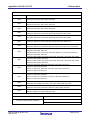
2. Target Devices
Below is a list of devices supported by the Applilet3 for RL78/I1A V2.03.01.03
PIN
Device name
20pin
R5F1076C
30pin
R5F107AC, R5F107AE
32pin
R5F107BC
38pin
R5F107DE
The Applilet3 is based on the following documents.
Manual Name
Document Number
R01UH0169JJ0210 Rev.2.10
RL78/I1A User's Manual: Hardware
R01UH0169EJ0210 Rev.2.10
Below is a list of devices supported by the Applilet3 for RL78/G12 V2.03.01.03
PIN
Device name
20pin
R5F10266, R5F10267, R5F10268, R5F10269, R5F1026A
R5F10366, R5F10367, R5F10368, R5F10369, R5F1036A
24pin
R5F10277, R5F10278, R5F10279, R5F1027A
R5F10377, R5F10378, R5F10379, R5F1037A
30pin
R5F102A7, R5F102A8, R5F102A9, R5F102AA
R5F103A7, R5F103A8, R5F103A9, R5F103AA
The Applilet3 is based on the following documents.
Manual Name
Document Number
R01UH0200JJ0200 Rev.2.00
RL78/G12 User's Manual: Hardware
R01UH0200EJ0200 Rev.2.00
R20UT3410EJ0100 Rev1.00
Mar 23,2015
Page 4 of 32
Applilet3 for RL78 V1.07.00
Release Note
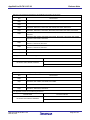
Below is a list of devices supported by the Applilet3 for RL78/G13 V2.03.01.03
PIN
Device name
20pin
R5F1006A, R5F1006C, R5F1006D, R5F1006E
R5F1016A, R5F1016C, R5F1016D, R5F1016E
24pin
R5F1007A, R5F1007C, R5F1007D, R5F1007E
R5F1017A, R5F1017C, R5F1017D, R5F1017E
25pin
R5F1008A, R5F1008C, R5F1008D, R5F1008E
R5F1018A, R5F1018C, R5F1018D, R5F1018E
30pin
R5F100AA, R5F100AC, R5F100AD, R5F100AE, R5F100AF, R5F100AG
R5F101AA, R5F101AC, R5F101AD, R5F101AE, R5F101AF, R5F101AG
32pin
R5F100BA, R5F100BC, R5F100BD, R5F100BE, R5F100BF, R5F100BG
R5F101BA, R5F101BC, R5F101BD, R5F101BE, R5F101BF, R5F101BG
36pin
R5F100CA, R5F100CC, R5F100CD, R5F100CE, R5F100CF, R5F100CG
R5F101CA, R5F101CC, R5F101CD, R5F101CE, R5F101CF, R5F101CG
40pin
R5F100EA, R5F100EC, R5F100ED, R5F100EE, R5F100EF, R5F100EG, R5F100EH
R5F101EA, R5F101EC, R5F101ED, R5F101EE, R5F101EF, R5F101EG, R5F101EH
R5F100FA, R5F100FC, R5F100FD, R5F100FE, R5F100FF, R5F100FG, R5F100FH
44pin
R5F100FJ, R5F100FK, R5F100FL
R5F101FA, R5F101FC, R5F101FD, R5F101FE, R5F101FF, R5F101FG, R5F101FH
R5F101FJ, R5F101FK, R5F101FL
R5F100GA, R5F100GC, R5F100GD, R5F100GE, R5F100GF, R5F100GG, R5F100GH
48pin
R5F100GJ, R5F100GK, R5F100GL
R5F101GA, R5F101GC, R5F101GD, R5F101GE, R5F101GF, R5F101GG, R5F101GH
R5F101GJ, R5F101GK, R5F101GL
R5F100JC, R5F100JD, R5F100JE, R5F100JF, R5F100JG, R5F100JH
52pin
R5F100JJ, R5F100JK, R5F100JL
R5F101JC, R5F101JD, R5F101JE, R5F101JF, R5F101JG, R5F101JH
R5F101JJ, R5F101JK, R5F101JL
R5F100LC, R5F100LD, R5F100LE, R5F100LF, R5F100LG, R5F100LH
64pin
R5F100LJ, R5F100LK, R5F100LL
R5F101LC, R5F101LD, R5F101LE, R5F101LF, R5F101LG, R5F101LH
R5F101LJ, R5F101LK, R5F101LL
80pin
100pin
128pin
R5F100MF, R5F100MG, R5F100MH, R5F100MJ, R5F100MK, R5F100ML
R5F101MF, R5F101MG, R5F101MH, R5F101MJ, R5F101MK, R5F101ML
R5F100PF, R5F100PG, R5F100PH, R5F100PJ, R5F100PK, R5F100PL
R5F101PF, R5F101PG, R5F101PH, R5F101PJ, R5F101PK, R5F101PL
R5F100SH, R5F100SJ, R5F100SK, R5F100SL
R5F101SH, R5F101SJ, R5F101SK, R5F101SL
The Applilet3 is based on the following documents.
Manual Name
Document Number
R01UH0146JJ0300 Rev.3.00
RL78/G13 User's Manual: Hardware
R01UH0146EJ0300 Rev.3.00
R20UT3410EJ0100 Rev1.00
Mar 23,2015
Page 5 of 32
Applilet3 for RL78 V1.07.00
Release Note
Below is a list of devices supported by the Applilet3 for RL78/G14 V2.04.01.03
PIN
Device name
30pin
R5F104AA, R5F104AC, R5F104AD, R5F104AE, R5F104AF, R5F104AG
32pin
R5F104BA, R5F104BC, R5F104BD, R5F104BE, R5F104BF, R5F104BG
36pin
R5F104CA, R5F104CC, R5F104CD, R5F104CE, R5F104CF, R5F104CG
40pin
R5F104EA, R5F104EC, R5F104ED, R5F104EE, R5F104EF, R5F104EG, R5F104EH
44pin
48pin
52pin
64pin
R5F104FA, R5F104FC, R5F104FD, R5F104FE, R5F104FF, R5F104FG, R5F104FH
R5F104FJ
R5F104GA, R5F104GC, R5F104GD, R5F104GE, R5F104GF, R5F104GG, R5F104GH
R5F104GJ, R5F104GK, R5F104GL
R5F104JC, R5F104JD, R5F104JE, R5F104JF, R5F104JG, R5F104JH
R5F104JJ, R5F104JK, R5F104JL
R5F104LC, R5F104LD, R5F104LE, R5F104LF, R5F104LG, R5F104LH
R5F104LJ, R5F104LK, R5F104LL
80pin
R5F104MF, R5F104MG, R5F104MH, R5F104MJ
100pin
R5F104PF, R5F104PG, R5F104PH, R5F104PJ
The Applilet3 is based on the following documents.
Manual Name
Document Number
R01UH0186JJ0200 Rev.2.00
RL78/G14 User's Manual: Hardware
R01UH0186EJ0200 Rev.2.00
Below is a list of devices supported by the Applilet3 for RL78/G1A V2.03.01.03
PIN
Device name
25pin
R5F10E8A, R5F10E8C, R5F10E8D, R5F10E8E
32pin
R5F10EBA, R5F10EBC, R5F10EBD, R5F10EBE
48pin
R5F10EGA, R5F10EGC, R5F10EGD, R5F10EGE
64pin
R5F10ELC, R5F10ELD, R5F10ELE
The Applilet3 is based on the following documents.
Manual Name
Document Number
R01UH0305JJ0200 Rev.2.00
RL78/G1A User's Manual: Hardware
R01UH0305EJ0200 Rev.2.00
R20UT3410EJ0100 Rev1.00
Mar 23,2015
Page 6 of 32
Applilet3 for RL78 V1.07.00
Release Note
Below is a list of devices supported by the Applilet3 for RL78/F12 V2.03.01.03
PIN
Device name
20pin
R5F1096E, R5F1096D, R5F1096C, R5F1096B, R5F1096A, R5F10968
30pin
R5F109AE, R5F109AD, R5F109AC, R5F109AB, R5F109AA
32pin
R5F109BE, R5F109BD, R5F109BC, R5F109BB, R5F109BA
48pin
R5F109GE, R5F109GD, R5F109GC, R5F109GB, R5F109GA
64pin
R5F109LE, R5F109LD, R5F109LC, R5F109LB, R5F109LA
The Applilet3 is based on the following documents.
Manual Name
Document Number
R01UH0231JJ0110 Rev.1.10
RL78/F12 User's Manual: Hardware
R01UH0231EJ0111 Rev.1.11
Below is a list of devices supported by the Applilet3 for RL78/L12 V2.03.01.03
PIN
Device name
32pin
R5F10RBC, R5F10RBA, R5F10RB8
44pin
R5F10RFC, R5F10RFA, R5F10RF8
48pin
R5F10RGC, R5F10RGA, R5F10RG8
52pin
R5F10RJC, R5F10RJA, R5F10RJ8
64pin
R5F10RLC, R5F10RLA
The Applilet3 is based on the following documents
Manual Name
Document Number
R01UH0330JJ0200 Rev.2.00
RL78/L12 User's Manual: Hardware
R01UH0330EJ0200 Rev.2.00
R20UT3410EJ0100 Rev1.00
Mar 23,2015
Page 7 of 32
Applilet3 for RL78 V1.07.00
Release Note
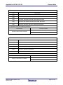
Below is a list of devices supported by the Applilet3 for RL78/D1A V2.03.01.03
PIN
Device name
48pin
R5F10CGB, R5F10CGC, R5F10DGC, R5F10DGD, R5F10DGE
64pin
R5F10CLD, R5F10DLD, R5F10DLE
80pin
R5F10CMD, R5F10CME
R5F10DMD, R5F10DME, R5F10DMF, R5F10DMG, R5F10DMJ
100pin
R5F10DPE, R5F10DPF, R5F10DPG, R5F10DPJ, R5F10TPJ
Applilet3 for RL78_D1A is based on the following documents
Manual Name
RL78/D1A User's Manual: Hardware
Document Number
R01UH0317EJ0100 Rev.1.00
Below is a list of devices supported by the Applilet3 for RL78/F13 V2.02.01.03
PIN
Device name
20pin
R5F10A6A, R5F10A6C, R5F10A6D, R5F10A6E
30pin
R5F10AAA, R5F10AAC, R5F10AAD, R5F10AAE
R5F10BAC, R5F10BAD, R5F10BAE, R5F10BAF, R5F10BAG
32pin
48pin
64pin
80pin
R5F10ABA, R5F10ABC, R5F10ABD, R5F10ABE
R5F10BBC, R5F10BBD, R5F10BBE, R5F10BBF, R5F10BBG
R5F10AGA, R5F10AGC, R5F10AGD, R5F10AGE, R5F10AGF, R5F10AGG
R5F10BGC, R5F10BGD, R5F10BGE, R5F10BGF, R5F10BGG
R5F10BLC, R5F10ALD, R5F10ALE, R5F10ALF, R5F10ALG
R5F10BLC, R5F10BLD, R5F10BLE, R5F10BLF, R5F10BLG
R5F10AME, R5F10AMF, R5F10AMG
R5F10BME, R5F10BMF, R5F10BMG
The Applilet3 is based on the following documents.
Manual Name
Document Number
R01UH0368JJ0100 Rev.1.00
RL78/F13,F14 User's Manual: Hardware
R01UH0368EJ0100 Rev.1.00
R20UT3410EJ0100 Rev1.00
Mar 23,2015
Page 8 of 32
Applilet3 for RL78 V1.07.00
Release Note
Below is a list of devices supported by the Applilet3 for RL78/F14 V2.02.01.03
PIN
Device name
30pin
R5F10PAD, R5F10PAE
32pin
R5F10PBD, R5F10PBE
48pin
R5F10PGD, R5F10PGE, R5F10PGF, R5F10PGG, R5F10PGH, R5F10PGJ
64pin
R5F10PLE, R5F10PLF, R5F10PLG, R5F10PLH, R5F10PLJ
80pin
R5F10PME, R5F10PMF, R5F10PMG, R5F10PMH, R5F10PMJ
100pin
R5F10PPE, R5F10PPF, R5F10PPG, R5F10PPH, R5F10PPJ
The Applilet3 is based on the following documents.
Manual Name
Document Number
R01UH0368JJ0100 Rev.1.00
RL78/F13,F14 User's Manual: Hardware
R01UH0368EJ0100 Rev.1.00
R20UT3410EJ0100 Rev1.00
Mar 23,2015
Page 9 of 32
Applilet3 for RL78 V1.07.00
Release Note
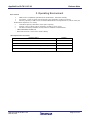
3. Operating Environment
Host machine
•
IBM PC/AT compatibles (Windows® 8, Windows® 7, Windows Vista®)
•
Processor: 1 GHz or higher (must support hyper-threading, multi-core CPUs)
•
Memory capacity: 2 GB or more recommended. Minimum requirement is 1 GB or more (64bit Windows requires 2 G or more)
•
Hard disk capacity: 200 MB or more spare capacity
•
Display: 1024 x 768 or higher resolution, 65,536 or more colors
•
All other necessary software environments in addition to WindowsOS
- .NET Framework version4.5
- Microsoft Visual C++ 2010 SP1 runtime library
Development Environments
Product Name
Version
IAR Embedded Workbench for Renesas RL78
V1.40.1 or later
KPIT GNURL78
V14.02 or later
Renesas electronics Compiler for 78K0R [CA78K0R]
V1.70 or later
Renesas electronics Compiler for RL78 [CC-RL]
V1.01 or later
R20UT3410EJ0100 Rev1.00
Mar 23,2015
Page 10 of 32
Applilet3 for RL78 V1.07.00
Release Note
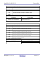
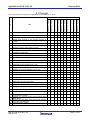
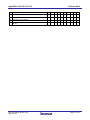
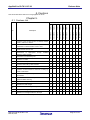
4. Changes
This chapter describes changes from Applilet3 for RL78 V1.05.01 to V1.06.00.
Corresponds of Applilet3
Changes of UART2 setup
12
Changes of key interrupt function
13
Changes of Simplified I2C
14
Additional function generation file mode
15
Changes of hdwinit() function
16
Changes of API about Simplified I2C by SAU
17
Changes of the timer RD and the timer RJ0
18
Changes of input pulse interval measurement of TAU
19
Changes the notation of a power supply
20
It corresponds to renewal of device user's manual.
21
Additional of the GCC code output
22
Changes the Key Input Interrupt Setting
23
Changes the A/D Converter Operation Setting
24
Changes the clock frequency of operation
25
Changes the watch error correction of real-time clock
26
Changes of CPU and peripheral clock (fCLK) in the
clock generator settings.
Changes for Using the Remote Control Carrier Wave
Mask Signal
Changes the Case When Ports that Are Not Available
in the MCU Are Displayed.
Changes Setting of Port1
27
28
29
R20UT3410EJ0100 Rev1.00
Mar 23,2015
V2.03.01.03
11
RL78/D1A
Changes of TAU1 setup
V2.03.01.03
10
RL78/I1A
Changes of PIOR setup
V2.04.01.03
9
RL78/G14
Changes of the TTL check box of a port
V2.03.01.03
8
RL78/G13
Changes of square wave output of a timer
V2.03.01.03
7
RL78/G12
GUI correction of an A/D converter
V2.03.01.03
6
RL78/G1A
5
Output code changes of the receiving function of
UARTn
Control correction of a competition pin
V2.03.01.03
4
RL78/F12
Addition of PMC register setup
V2.03.01.03
3
RL78/L12
Output code changes of serial array unit
V2.02.01.03
2
RL78/F14
Output code changes of real-time clock
V2.02.01.03
1
RL78/F13
内容
No
-
-
/
/
/
/
/
/
/
/
/
/
/
/
-
-
-
/
-
/
-
/
/
/
/
/
/
/
/
/
/
/
-
/
/
/
/
/
/
/
/
/
/
/
-
/
/
/
/
/
/
/
/
/
/
/
/
/
/
/
/
/
/
/
/
/
/
/
/
/
/
/
/
/
/
/
/
/
/
/
/
/
/
/
/
/
/
/
/
/
/
/
/
/
/
/
/
/
/
/
/
/
/
/
/
/
/
/
/
/
/
/
/
/
/
/
/
/
/
/
/
/
/
/
/
/
/
/
/
/
/
/
/
/
/
/
/
/
/
/
/
/
/
/
/
/
/
/
/
/
/
/
/
/
/
/
/
/
-
/
/
/
/
/
/
/
/
/
/
/
/
/
/
-
/
/
/
/
/
/
/
/
/
-
/
/
Page 11 of 32
Applilet3 for RL78 V1.07.00
30
Changes setting of interval timer
31
Changes for CPU stack pointer monitor function
32
Changes for comparator setting
33
Changes for DTC setting
34
○
Release Note
/
○
/
○
○
/
/
/
○
○
○
/
/
/
○
/
/
/
/
/
○
/
/
/
○
Changes for the voltage detection circuit to “Interrupt
Mode”
: Correspondence, -: Not correspondence(finish of correction), /: Outside of function
R20UT3410EJ0100 Rev1.00
Mar 23,2015
○
/
/
/
/
○
/
/
/
/
○
/
/
/
/
○
/
○
/
○
/
/
/
/
/
Page 12 of 32
Applilet3 for RL78 V1.07.00
Release Note
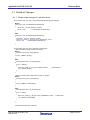
4.1 Details of Changes
4.1.1 Output code changes of real-time clock
a) The output code of R_RTC_Set_ConstPeriodInterruptOff() was changes.
Before:
void R_RTC_Set_ConstPeriodInterruptOff(void)
{
RTCC0 &= _88_RTC_INTRTC_CLEAR;
RTCIF = 0U;
/* clear INTRTC interrupt flag */
}
After:
void R_RTC_Set_ConstPeriodInterruptOff(void)
{
RTCC0 &= _F8_RTC_INTRTC_CLEAR;
RTCC1 &= (uint8_t)~_08_RTC_INTC_GENERATE_FLAG;
RTCIF = 0U;
/* clear INTRTC interrupt flag */
}
b) The output code of R_RTC_Interrupt( ) was changes.
- When an alarm interrupt function is checked.
Before:
__interrupt void R_RTC_Interrupt(void)
{
R_RTC_Callback_Alarm();
}
After:
__interrupt static void r_rtc_interrupt(void)
{
if (1U == WAFG)
{
RTCC1 &= (uint8_t)~_10_RTC_ALARM_MATCH;
r_rtc_callback_alarm();
}
/* clear WAFG */
}
- When a constant-period interruption function is checked
Before:
__interrupt void R_RTC_Interrupt(void)
{
R_RTC_Callback_ConstPeriod();
}
After:
__interrupt static void r_rtc_interrupt(void)
{
if (1U == RIFG)
{
RTCC1 &= (uint8_t)~_08_RTC_INTC_GENERATE_FLAG;
r_rtc_callback_constperiod();
}
/* clear RIFG */
}
a) and b) issues has been corrected
R20UT3410EJ0100 Rev1.00
Mar 23,2015
Page 13 of 32
Applilet3 for RL78 V1.07.00
Release Note
4.1.2 Output code changes of serial array unit
a) The following function which was not supported by SAU1 was added.
void R_SAU0_Set_SnoozeOn(void)
void R_SAU0_Set_SnoozeOff(void)
b) The function of simple IIC was changed.
Before:
void R_IIC00_StartCondition(void)
{
SO0 &= ~_0001_SAU_CH0_DATA_OUTPUT_1; /* clear IIC00 SDA */
SOE0 |= _0001_SAU_CH0_OUTPUT_ENABLE; /* enable IIC00 output */
SO0 &= ~_0100_SAU_CH0_CLOCK_OUTPUT_1;
/* clear IIC00 SCL */
SS0 |= _0001_SAU_CH0_START_TRG_ON;
/* enable IIC00 */
}
After:
void R_IIC00_StartCondition(void)
{
volatile uint8_t w_count;
SO0 &= ~_0001_SAU_CH0_DATA_OUTPUT_1;
/* clear IIC00 SDA */
/* Wait for 5us */
for (w_count = 0U; w_count <= IIC00_WAITTIME; w_count++)
{
NOP();
}
SO0 &= ~_0100_SAU_CH0_CLOCK_OUTPUT_1; /* clear IIC00 SCL */
SOE0 |= _0001_SAU_CH0_OUTPUT_ENABLE;
/* enable IIC00 output */
SS0 |= _0001_SAU_CH0_START_TRG_ON;
/* enable IIC00 */
}
Before:
void R_IIC00_StopCondition(void)
{
ST0 |= _0001_SAU_CH0_STOP_TRG_ON;
/* disable IIC00 */
SOE0 &= ~_0001_SAU_CH0_OUTPUT_ENABLE;
/* disable IIC00 output */
SO0 &= ~_0001_SAU_CH0_DATA_OUTPUT_1; /* clear IIC00 SDA */
SO0 |= _0100_SAU_CH0_CLOCK_OUTPUT_1; /* set IIC00 SCL */
SO0 |= _0001_SAU_CH0_DATA_OUTPUT_1; /* set IIC00 SDA */
}
After:
void R_IIC00_StopCondition(void)
{
volatile uint8_t w_count;
ST0 |= _0001_SAU_CH0_STOP_TRG_ON;
/* disable IIC00 */
SOE0 &= ~_0001_SAU_CH0_OUTPUT_ENABLE;
/* disable IIC00 output */
SO0 &= ~_0001_SAU_CH0_DATA_OUTPUT_1;
/* clear IIC00 SDA */
SO0 |= _0100_SAU_CH0_CLOCK_OUTPUT_1; /* set IIC00 SCL */
/* Wait for 5us */
for (w_count = 0U; w_count <= IIC00_WAITTIME; w_count++)
{
NOP();
}
SO0 |= _0001_SAU_CH0_DATA_OUTPUT_1;
/* set IIC00 SDA */
}
R20UT3410EJ0100 Rev1.00
Mar 23,2015
Page 14 of 32
Applilet3 for RL78 V1.07.00
Release Note
c) The interrupt handler function of simple IIC was corrected.
- It was made not to take out an error with the last byte's NACK.
Before:
if ((SSR00 & _0002_SAU_PARITY_ERROR) == 0x0002U)
{
R_IIC00_Callback_Master_Error(MD_NACK);
}
After:
if (((SSR00 & _0002_SAU_PARITY_ERROR) == 0x0002U) && (g_iic00_tx_count != 0U))
{
r_iic00_callback_master_error(MD_NACK);
}
- Deletion of an unnecessary code
Before:
if ((g_Iic00MasterStatusFlag & _04_SAU_IIC_SENDED_ADDRESS_FLAG) == 0U)
{
rxadr = SIO00;
SCR00 &= ~_C000_SAU_RECEPTION_TRANSMISSION;
SCR00 |= _4000_SAU_RECEPTION;
g_Iic00MasterStatusFlag |= _04_SAU_IIC_SENDED_ADDRESS_FLAG;
SIO00 = 0xFFU;
}
After:
if ((g_iic00_master_status_flag & _04_SAU_IIC_SENDED_ADDRESS_FLAG) == 0U)
{
ST0 |= _0001_SAU_CH0_STOP_TRG_ON;
SCR00 &= ~_C000_SAU_RECEPTION_TRANSMISSION;
SCR00 |= _4000_SAU_RECEPTION;
SS0 |= _0001_SAU_CH0_START_TRG_ON;
g_iic00_master_status_flag |= _04_SAU_IIC_SENDED_ADDRESS_FLAG;
SIO00 = 0xFFU;
}
a) , b) and c) issues has been corrected .
R20UT3410EJ0100 Rev1.00
Mar 23,2015
Page 15 of 32
Applilet3 for RL78 V1.07.00
Release Note
4.1.3 Addition of PMC register setup
A setup of the PMC register was added about the combination terminal of each circumference.
[The terminal to which a PMC register setup was added]
●20,24,25,30, 32pin devices
P00/ANI17/TI00/TxD1
P01/ANI16/TO00/RxD1
●other devices
P02/ANI17/SO10/TxD1
P03/ANI16/SI10/RxD1/SDA10
This issue has been corrected
4.1.4 Output code changes of the receiving function of UARTn
The output code of the receiving function of UARTn was corrected. The following is a case of UART0.
[ r_cg_serial.c ]
MD_STATUS R_UART0_Receive(uint8_t * const rx_buf, uint16_t rx_num)
{
MD_STATUS status = MD_OK;
if (rx_num < 1U)
{
status = MD_ARGERROR;
}
else
{
g_uart0_rx_count = 0U;
g_uart0_rx_length = rx_num;
gp_uart0_tx_address = rx_buf;
}
return (status);
}
Before : gp_uart0_tx_address = rx_buf;
After :
gp_uart0_rx_address = rx_buf;
This issue has been corrected
4.1.5 Control correction of a competition pin
Control of the competition pin when simple-I2C of 24 and 25 pin device of RL78/G13 is set up was
corrected.
Before :
P17/SDA11
After :
P50/SDA11
P30/SCL11
P30/SCL11
This issue has been corrected
R20UT3410EJ0100 Rev1.00
Mar 23,2015
Page 16 of 32
Applilet3 for RL78 V1.07.00
Release Note
4.1.6 GUI correction of an A/D converter
In the A/D converter, it corrected so that the message displayed with the fixed value as the number of
analog input channels might be dynamically displayed according to a number of channels.
This issue has been corrected
4.1.7 Changes of square wave output of a timer
If code is generated so that timers TAUx (x is 1 to 7) of an 80-, 100-, or 128-pin MCU can output square
wave, the values of the TOM1 and TOL1 registers, which control TAUx, are not set but those of the
TOM0 and TOL0 registers are set.
This issue has been corrected
4.1.8 Changes of the TTL check box of a port
There is no check box which sets TTL as P10 and P11 with 30-pin MCU.
This issue has been corrected
4.1.9 Changes of PIOR setup
In the code for setting registers PIOR01 and PIOR04 to 1s in an arrangement of pin assignments,
incorrect pins are assigned to INTP10 and INTP11 as follows:
Incorrect:
Correct:
P110 assigned to INTP10
P100 assigned to INTP10
P111 assigned to INTP11
P110 assigned to INTP11
This issue has been corrected
4.1.10 Changes of TAU1 setup
If code is generated in an 80- or 100-pin MCU, no one except "interval" can be selected in the functional
selection of timer TAU1.
This issue has been corrected
R20UT3410EJ0100 Rev1.00
Mar 23,2015
Page 17 of 32
Applilet3 for RL78 V1.07.00
Release Note
4.1.11 Changes of UART2 setup
If the code is generated for making settings of UART2 and any of the ports except 13 and 14, an error
arises in building it.
Example:
If you use UART2 and set ports 10, 11, and 12 to the output state, the following code is generated;
however, the last "|" is unnecessary:
PMC1 = ・・・ | _80_PMCn7_NOT_USE | ;
If build is performed including this code, an error arises. It must be read as follows:
PMC1 = ・・・ | _80_PMCn7_NOT_USE ;
This issue has been corrected
4.1.12 Changes of key interrupt function
If you make settings of the key interrupt flag and the triggering edge, the settings cannot properly be
reflected to the KRCTL register by the generated code.
Example:
If you select Use among from the key flag pull-down list and Falling Edge among from the triggering edge
pull-down list, the Applilet3 generates the following incorrect codes.
KRCTL |= _00_KR_FLAG_UNUSED;
KRCTL |= _01_KR_EDGE_RISING;
The correct codes are as follows:
KRCTL |= _01_KR_FLAG_USED;
KRCTL |= _00_KR_EDGE_FALLING;
This issue has been corrected
4.1.13 Changes of Simplified I2C
I When a receiving byte is set to 1 by Simplified I2C, it does not operate normally.
This issue has been corrected
R20UT3410EJ0100 Rev1.00
Mar 23,2015
Page 18 of 32
Applilet3 for RL78 V1.07.00
Release Note
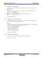
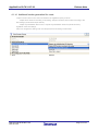
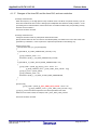
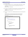
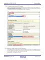
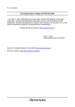
4.1.14 Additional function generation file mode
"Output control of API function" has been added to the Applilet3 Property for RL78.
"Output all API functions according to the setting": Outputs necessary API functions according to the
GUI settings (conventional output method).
"Output only initialization API function": Outputs only initialization functions (Create functions)
regardless of the GUI settings.
Users can configure the settings such as interrupt functions according to their needs.
R20UT3410EJ0100 Rev1.00
Mar 23,2015
Page 19 of 32
Applilet3 for RL78 V1.07.00
Release Note
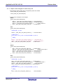
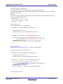
4.1.15 Changes of hdwinit() function
We have changed the initial code for the hdwinit() and main() functions.
void hdwinit(void)
{
DI();
R_Systeminit();
EI();
}
The above code has been changed to the code given below. Accordingly, interrupts are not enabled
within the hdwinit function.
void hdwinit(void)
{
DI();
R_Systeminit();
}
Interrupts are now enabled within the main() function.
/***********************************************************************************************************************
* Function Name: main
* Description : This function implements main function.
***********************************************************************************************************************/
void main(void)
{
R_MAIN_UserInit();
/* Start user code. Do not edit comment generated here */
while (1U)
{
;
}
/* End user code. Do not edit comment generated here */
}
/***********************************************************************************************************************
* Function Name: R_MAIN_UserInit
* Description : This function adds user code before implementing main function.
***********************************************************************************************************************/
void R_MAIN_UserInit(void)
{
/* Start user code. Do not edit comment generated here */
EI();
/* End user code. Do not edit comment generated here */
}
R20UT3410EJ0100 Rev1.00
Mar 23,2015
Page 20 of 32
Applilet3 for RL78 V1.07.00
Release Note
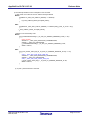
When an old project is used in code generation, the definitions of variables within the main function may
lead to errors.
[Old project]
void main(void)
{
/* Start user code. Do not edit comment generated here */
char c;
while (1U)
{
...
[When an old project is loaded into CubeSuite+V1.03.00 and used for code generation]
void main(void)
{
R_MAIN_UserInit();
/* Start user code. Do not edit comment generated here */
char c;
<- error!!
while (1U)
{
...
In that case, use { }.
void main(void)
{
R_MAIN_UserInit();
/* Start user code. Do not edit comment generated here */
{
<- add “{“
char c;
<- not error!
while (1U)
{
...
}
}
<- add “}”
4.1.16 Changes of API about Simplified I2C by SAU
The R_IICmn_StartCondition of Simplified I2C of SAU and the R_IICmn_StopCondition were changed.
The waiting code for time required for generation of the start condition of Simplified I2C standard and stop
condition was added.
This issue has been corrected
R20UT3410EJ0100 Rev1.00
Mar 23,2015
Page 21 of 32
Applilet3 for RL78 V1.07.00
Release Note
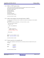
4.1.17 Changes of the timer RD and the timer RJ0, and new restriction
a) Change of the timer RD
When the frequency of the high-speed on-chip oscillator clock is 64 MHz, the period and duty cycle for
timer RD in PWM mode are incorrect. Although pins multiplexed with PWM are usually marked "!" in the
port-setting view to indicate that the other functions are not usable in PWM mode, port pins being used by
timer RD are not marked "!".
This issue has been corrected
b) Change of the timer RJ0
Change of the fault in timer RJ pulse period measurement mode.
Specify desired values for the count source and TRJIO0 polarity, and 0xffff for the count value. After code
generation by CubeSuite+, correct a part of the output interrupt handler in the following way.
[Output source code]
__interrupt static void r_tmr_rj0_interrupt(void)
{
if ((TRJCR0 & _20_TMRJ_UNDERFLOW_OCCUR) != 0U)
{
g_tmrj0_underflow_count += 1U;
TRJCR0 &= (uint8_t)~_20_TMRJ_UNDERFLOW_OCCUR;
}
if ((TRJCR0 & _10_TMRJ_ACTIVE_EDGE_UNRECEIVED) != 0U)
{
g_tmrj0_width = (uint32_t)(g_tmrj0_trj_count - TRJ0 + 1U +
(g_tmrj0_underflow_count * (_FFFF_TMRJ_TRJ0_VALUE + 1U)));
g_tmrj0_trj_count = (uint32_t)TRJ0;
g_tmrj0_underflow_count = 0U;
TRJCR0 &= (uint8_t)~_10_TMRJ_ACTIVE_EDGE_UNRECEIVED;
}
}
[Correct code]
g_tmrj0_width = (uint32_t)(_FFFF_TMRJ_TRJ0_VALUE - TRJ0 + 1U +
(g_tmrj0_underflow_count * (_FFFF_TMRJ_TRJ0_VALUE + 1U)));
g_tmrj0_trj_count in the above expression must be the specified count value.
When the count value is 0xffff, for example, enter _FFFF_TMRJ_TRJ0_VALUE.
This issue has been corrected
R20UT3410EJ0100 Rev1.00
Mar 23,2015
Page 22 of 32
Applilet3 for RL78 V1.07.00
Release Note
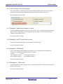
c) Addition of restriction about timer RJ0
The interruption function in timer RJ0 pulse width measurement mode has fault.
If you select pulse width measurement from among the operating modes of the RJ0 timer, the Applilet3
generates erroneous code
Example:
If you make the above settings for the RJ0 timer and use the Applilet3 under the following settings, errors
arise in the generated interrupt handler:
- Count source:
any
- Polarity of TRJIO0: positive or negative
- Count value:
0x64
[Output source code]
__interrupt static void r_tmr_rj0_interrupt(void)
{
if ((TRJCR0 & _20_TMRJ_UNDERFLOW_OCCUR) != 0U)
{
g_tmrj0_underflow_count += 1U;
TRJCR0 &= (uint8_t)~_20_TMRJ_UNDERFLOW_OCCUR;
}
if ((TRJCR0 & _10_TMRJ_ACTIVE_EDGE_UNRECEIVED) != 0U)
{
g_tmrj0_width = (uint32_t)(_0064_TMRJ_TRJ0_VALUE - TRJ0 + 1U +
(g_tmrj0_underflow_count * (_0064_TMRJ_TRJ0_VALUE + 1U)));
g_tmrj0_underflow_count = 0U;
TRJCR0 &= (uint8_t)~_10_TMRJ_ACTIVE_EDGE_UNRECEIVED;
}
}
[The code to correct ]
volatile uint32_t g_tmrj0_trj_count = 0U;
(A global variable is added)
__interrupt static void r_tmr_rj0_interrupt(void)
{
if ((TRJCR0 & _20_TMRJ_UNDERFLOW_OCCUR) != 0U)
{
g_tmrj0_underflow_count += 1U;
TRJCR0 &= (uint8_t)~_20_TMRJ_UNDERFLOW_OCCUR;
}
if ((TRJCR0 & _10_TMRJ_ACTIVE_EDGE_UNRECEIVED) != 0U)
{
g_tmrj0_width = (uint32_t)(g_tmrj0_trj_count - TRJ0 + 1U +
(g_tmrj0_underflow_count * (_0064_TMRJ_TRJ0_VALUE + 1U)));
g_tmrj0_trj_count = (uint32_t)TRJ0;
g_tmrj0_underflow_count = 0U;
TRJCR0 &= (uint8_t)~_10_TMRJ_ACTIVE_EDGE_UNRECEIVED;
}
}
C) issue has been corrected
R20UT3410EJ0100 Rev1.00
Mar 23,2015
Page 23 of 32
Applilet3 for RL78 V1.07.00
4.1.18
Release Note
Changes of input pulse interval measurement of TAU
It corrected that the right measured value was not able to be acquired for the input pulse interval
measurement function of TAU, and a high / low width measurement function by interruption function
r_taux_channelx_interrupt() at the time of use.
This issue has been corrected
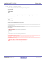
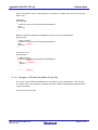
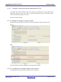
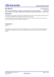
4.1.19 Changes the notation of a power supply
Although there was not EVDD in RL78/G12 device, it corrected that the notation remained on GUI.
[before]
[after]
This issue has been corrected in Applilet3 for RL78,78K0R,78K0 V2.00.00.
4.1.20 It corresponds to renewal of device user's manual
It corresponded to the contents of device user's manual to revision up.
R20UT3410EJ0100 Rev1.00
Mar 23,2015
Page 24 of 32
Applilet3 for RL78 V1.07.00
Release Note
4.1.21 Additional of the GCC code output
It came to be able to carry out the GCC code output.
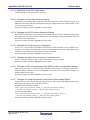
4.1.22 Changes the Key Input Interrupt Setting
The setting of Key interrupt flag and Detection edge may not be saved. When saving the project after
making the new setting and then reloading the project, the setting reverts to the original setting as the
new one had not been saved.
This issue has been corrected in Applilet3 for RL78 V1.04.00
4.1.23 Changes the A/D Converter Operation Setting
The Conversion time mode of the Conversion time setting may not be saved. When saving the project
after making the new setting and then reloading the project, the setting reverts to the original setting as
the new one had not been saved.
This issue has been corrected in Applilet3 for RL78 V1.04.00
4.1.24 Changes the clock frequency of operation
The list of 2, 3, and six MHz was added to the frequency of the high-speed on-chip oscillator clock.
Therefore, if the project before Cubesuite+V2.03.00 is read, the clock frequency of a high-speed on-chip
oscillator may shift. Please re-set up the frequency right in that case.
This issue has been corrected in Applilet3 for RL78 V1.04.00
4.1.25 Changes the watch error correction of real-time clock
The error correction of real-time clock function of the real-time clock was deleted.
This issue has been corrected in Applilet3 for RL78 V1.04.00
4.1.26 Changes of CPU and peripheral clock (fCLK) in the clock generator settings
When the 20-pin, 30-pin, or 32-pin package is selected for the RL78/F13 or RL78/F14 group and a
divided frequency is selected for CPU and peripheral clock (fCLK) in the clock generator settings, the
register settings are not output
This issue has been corrected in Applilet3 for RL78 V1.05.00
4.1.27 Changes for Using the Remote Control Carrier Wave Mask Signal
Change an error in the R_TAU0_Channel2_Stop function for output when PWM output (remote control
carrier wave mask signal) is selected in timer channel 2.
Example:Source code before modified
TO0 &= ~_0004_TAU_CH2_OUTPUT_VALUE_1 | ~_0008_TAU_CH3_OUTPUT_VALUE_1 |
~_0010_TAU_CH4_OUTPUT_VALUE_1 | ~_0020_TAU_CH5_OUTPUT_VALUE_1;
Source code after modified
TO0 &= ~_0004_TAU_CH2_OUTPUT_VALUE_1 & ~_0008_TAU_CH3_OUTPUT_VALUE_1 &
~_0010_TAU_CH4_OUTPUT_VALUE_1 & ~_0020_TAU_CH5_OUTPUT_VALUE_1;
This issue has been corrected in Applilet3 for RL78 V1.05.00
R20UT3410EJ0100 Rev1.00
Mar 23,2015
Page 25 of 32
Applilet3 for RL78 V1.07.00
Release Note
4.1.28 Changes the Case When Ports that Are Not Available in the MCU Are
Displayed
When an RL78/G14 group MCU in the 80-pin package is selected, the settings for the P80 and P81 ports,
which are not available in the selected MCU, are displayed.
This issue has been corrected in Applilet3 for RL78 V1.05.00
4.1.29 Changes Setting of Port1
When the port (P12, P13, P16, P17) for port1, the Code Generator outputs the unnecessary operator and
value "| _33_PMC1_DEFAULT". This is because the initial settings for unused bits in the PMC1 register
are incorrect.
This issue has been corrected in Applilet3 for RL78 V1.06.00
4.1.30 Changes setting of interval timer
On the Channel 1 and Channel 3 tabbed pages when "Timer" is selected in the tree view, selecting
"Higher and lower 8 bits" under "Interval mode setting" leads to "Generates INTTM01 when counting is
started" being grayed out to indicate that it has become non-selectable.
This issue has been corrected in Applilet3 for RL78 V1.07.00
4.1.31 Changes for CPU stack pointer monitor function
The order of statements in the procedure for setting the registers for CPU stack pointer monitor function*
is erroneous as shown below.
Note: CPU stack pointer monitor function is a security function of the MCU.
This issue has been corrected in Applilet3 for RL78 V1.07.00
4.1.32 Changes for comparator setting
When a comparator is set, code for clock supply is not output.
This issue has been corrected in Applilet3 for RL78 V1.07.00
4.1.33 Changes for DTC setting
A project is not saved after code generation when high-speed transfer by the DTC is set.
DTC activating source numbers are not set correctly for the DTC vector addresses.
This issue has been corrected in Applilet3 for RL78 V1.07.00
4.1.34 Changes for the voltage detection circuit to “Interrupt Mode”
Operation of the voltage detection circuit is in "reset mode" even if "interrupt mode" is selected.
This issue has been corrected in Applilet3 for RL78 V1.07.00
R20UT3410EJ0100 Rev1.00
Mar 23,2015
Page 26 of 32
Applilet3 for RL78 V1.07.00
Release Note
5. Cautions
This section describes cautions for using Applilet3 for RL78
Chapter 5.
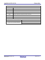
5.1 Cautions List
Corresponds of Applilet3
RL78/D1A
RL78/I1A
RL78/G14
RL78/G13
RL78/G12
RL78/G1A
RL78/F12
RL78/L12
RL78/F14
RL78/F13
No.
Description
V2.03.01.03
V2.03.01.03
V2.04.01.03
V2.03.01.03
V2.03.01.03
V2.03.01.03
V2.03.01.03
V2.03.01.03
V2.02.01.03
V2.02.01.03
1
Cautions of the LIN-bus function of UART0, UART2,
UART3, UART6 or UARTF.
○
○
○
○
○
○
○
○
○
○
2
Cautions of extension code, wakeup function and
multimaster of serial interface IICA or IIC0
○
○
○
○
○
○
○
○
○
○
3
Cautions of the operation for slave transmission of
serial interface IICA or IIC0.
-
-
/
/
/
-
-
-
-
-
4
Restrictions of High-speed
frequency select register
○
○
○
○
○
○
○
○
/
○
5
Restriction of a serial array unit
/
/
/
/
/
/
/
/
○
/
6
Cautions of PORT
-
-
/
/
/
-
-
-
-
-
7
Cautions of setup of a real-time clock
-
-
/
/
/
/
-
-
-
/
8
Cautions when using a DTC function
/
/
/
/
/
/
/
○
/
/
9
Cautions of initial function of an A/D converter
-
-
/
/
/
-
-
-
/
/
10
Cautions of initial function at the time of setting up
UART transmission
-
-
/
/
/
-
-
-
/
/
11
Cautions of Complementary assistant PWM mode
of TimerRD
/
/
/
/
/
/
/
-
/
/
12
Restrictions of internal low-speed or internal highspeed oscillator trimming
○
○
○
○
○
○
○
○
○
○
13
Cautions of Safety Functions
○
○
○
○
○
○
○
○
○
○
14
Cautions of file merge
○
○
○
○
○
○
○
○
○
○
15
Cautions of timer array unit input clock sauce
○
○
/
/
/
/
/
/
/
/
16
Cautions of a high-speed on-chip oscillator
○
○
○
○
○
○
○
○
○
○
17
Cautions of Voltage Dedector function
○
○
○
/
○
/
/
/
/
/
on-chip
oscillator
○ : Correspondence, -: Not correspondence, /:Outside of function.
R20UT3410EJ0100 Rev1.00
Mar 23,2015
Page 27 of 32
Applilet3 for RL78 V1.07.00
Release Note
5.2 Cautions Details
5.2.1 Cautions of the LIN-bus function of UART0,UART2,UART3,UART6 or UARTF
The Applilet3 is not supporting the LIN-bus functions of serial interface UART0, UART2, UART3,
UART6 or UARTF.
[Workaround] There is no workaround.
5.2.2 Cautions of the operation for slave transmission of serial interface IICA or IIC0
The Applilet3 is not supporting the extension code, multimaster, wakeup function of serial
interface IIC.
[Workaround] There is no workaround.
5.2.3 Cautions of extension code, multimaster,wakeup function of serial interface IICA
or IIC0
During slave transmission, if the master receiver does not return an ACK after the final data is
received, then the error API IICA_SlaveErrorCallback(MD_NACK) will be called, regardless of
whether the actual slave transmission process ended. For this reason, the program will not
terminate normally.
[Work-around] RL78 Applilet3 is corrected
void IICA_SlaveHandler(void)
{
・・・
if (TRC0 == 1U)
{
if ((ACKD0 == 0U) && (gIicaTxCnt != 0))
{
IICA_SlaveErrorCallback(MD_NACK);
}
else
{
if (gIicaTxCnt > 0U)
{
IICA = *gpIicaTxAddress;
gpIicaTxAddress++;
gIicaTxCnt--;
}
else
{
IICA_SlaveSendEndCallback();
WREL0 = 1U;
}
}
}
}
R20UT3410EJ0100 Rev1.00
Mar 23,2015
Page 28 of 32
Applilet3 for RL78 V1.07.00
Release Note
5.2.4 Restrictions of High-speed on-chip oscillator frequency select register
Applilet3 is not equivalent to a setup of high-speed on-chip oscillator frequency select register
[Workaround] There is no workaround.
5.2.5 Restriction of a serial array unit
Applilet3 is not equivalent to a setup of single-wire UART mode and DMX512
communication
[Workaround] There is no workaround.
5.2.6 Cautions of PORT
There are notes in the port setting of RL78/G13(R5F100LJ, R5F100LK, R5F100LL).
Please do not use a item of P43, P52, P53, and P54 ("TTL buffer" or "N-ch").
[Workaround]
RL78 Applilet3 is corrected
5.2.7 Cautions of a setup of a real-time clock
When a clock sauce is set to 15(fIL)kHz on device, clock function cannot be used. However, it is
displayed on GUI that clock function seems to be used with 15(fIL)kHz. Please do not set up clock
function.
[Workaround]
RL78 Applilet3 is corrected
R20UT3410EJ0100 Rev1.00
Mar 23,2015
Page 29 of 32
Applilet3 for RL78 V1.07.00
Release Note
5.2.8 Cautions when using a DTC function
When DTC is used, please set up the following individual option of building. The DATA section is added for
DTC to output sauce file "r_cg_dtc.c." Unless the individual option is set up, the following warning message is
displayed and an object file is not generated.
( CC78K0R warning W0837: Output assembler source file , not object file )
[Workaround]
There is no workaround
5.2.9 Cautions of initial function of an A/D converter
After making the port 2 a setup which does not compete with an A/D converter, the initialization function at
the time of setting up an analog input terminal by an A/D converter has an error. Source code outputted by
R_ADC_Create() "PM2 |= 0x??;” The value of 0x?? has an error.
[Workaround]
RL78 Applilet3 is corrected
R20UT3410EJ0100 Rev1.00
Mar 23,2015
Page 30 of 32
Applilet3 for RL78 V1.07.00
Release Note
5.2.10 Cautions of initial function at the time of setting up UART transmission
The source code of a SDRmn register setup is not outputted to initialization function R_UARTn_Create() at
the time of choosing only UART transmission.
[Workaround]
R78 Applilet3 is corrected .
5.2.11 Cautions of Complementary assistant PWM mode of TimerRD
When TimerRD Complementary PWM mode is used using a high-speed system clock by clock setup of
RL78/G14, it is necessary to change a setup of an option byte. RL78/G14 512 pages of R01UH0186JJ0100
Rev.1.00 edited by user's manual hardware Please refer to Notes 1.
[Workaround]
RL78 Applilet3 is corrected
5.2.12 Restrictions of internal low-speed or internal high-speed oscillator trimming
Applilet3 is not equivalent to a setup of internal low-speed or internal high-speed oscillator trimming register
[Workaround]
There is no workaround.
5.2.13 Cautions of Safety Functions
RAM parity error detection function of Safety Functions has not corresponded.
[Workaround]
There is no workaround.
5.2.14 Cautions of file merge
If you select Merge File in Generate File Mode in the property of Applilet3 and the source codes are written
between each comment below, the file will be merged.
/* Start user code. Do not edit comment generated here */
/* End user code. Do not edit comment generated here */
However, if the number of braces ("{" and "}") in the edited source codes
(including the comments) are not the same, the edited source codes may disappear
when you run the Applilet3
[Workaround]
There is no workaround.
5.2.15 Cautions of timer array unit input clock sauce
When the clock sauce of a timer input is set as a RTC1HZ output by setup of a timer array unit, a setup
about the output of the RTC1HZ terminal of a real-time clock becomes invalid.The code which outputs
RTC1HZ then is not generated.
[Workaround]
R20UT3410EJ0100 Rev1.00
Mar 23,2015
When you set to a RTC1HZ signal by setup of a timer array unit, please
choose a setup which uses a real-time clock and add the code which outputs
RTC1HZ.
Page 31 of 32
Applilet3 for RL78 V1.07.00
Release Note
5.2.16 Cautions of a high-speed on-chip oscillator
When a high-speed on-chip oscillator clock is set up by CubeSuite+ RL78, 78K0R, and 78K0 code generator
V2.01.00 or earlier, If it is read by CubeSuite+V2.03.00, a clock frequency setup of a high-speed on-chip
oscillator may not be right.
Please re-set up the frequency right in that case.
[Workaround]
There is no workaround.
5.2.17 Cautions of Voltage Detector function
When it interrupts in a Voltage Detector function and the interrupt mode is chosen, the preset value of
LVIMDS1 is 0. However, 1 will be set up in Applilet3 for RL78 V1.06.00.
[Workaround]
R20UT3410EJ0100 Rev1.00
Mar 23,2015
Please set up so that bit1 of the option byte C1H is set to 0.
Page 32 of 32
Notice
1.
Descriptions of circuits, software and other related information in this document are provided only to illustrate the operation of semiconductor products and application examples. You are fully responsible for
the incorporation of these circuits, software, and information in the design of your equipment. Renesas Electronics assumes no responsibility for any losses incurred by you or third parties arising from the
use of these circuits, software, or information.
2.
Renesas Electronics has used reasonable care in preparing the information included in this document, but Renesas Electronics does not warrant that such information is error free. Renesas Electronics
3.
Renesas Electronics does not assume any liability for infringement of patents, copyrights, or other intellectual property rights of third parties by or arising from the use of Renesas Electronics products or
assumes no liability whatsoever for any damages incurred by you resulting from errors in or omissions from the information included herein.
technical information described in this document. No license, express, implied or otherwise, is granted hereby under any patents, copyrights or other intellectual property rights of Renesas Electronics or
others.
4.
You should not alter, modify, copy, or otherwise misappropriate any Renesas Electronics product, whether in whole or in part. Renesas Electronics assumes no responsibility for any losses incurred by you or
5.
Renesas Electronics products are classified according to the following two quality grades: "Standard" and "High Quality". The recommended applications for each Renesas Electronics product depends on
third parties arising from such alteration, modification, copy or otherwise misappropriation of Renesas Electronics product.
the product's quality grade, as indicated below.
"Standard": Computers; office equipment; communications equipment; test and measurement equipment; audio and visual equipment; home electronic appliances; machine tools; personal electronic
equipment; and industrial robots etc.
"High Quality": Transportation equipment (automobiles, trains, ships, etc.); traffic control systems; anti-disaster systems; anti-crime systems; and safety equipment etc.
Renesas Electronics products are neither intended nor authorized for use in products or systems that may pose a direct threat to human life or bodily injury (artificial life support devices or systems, surgical
implantations etc.), or may cause serious property damages (nuclear reactor control systems, military equipment etc.). You must check the quality grade of each Renesas Electronics product before using it
in a particular application. You may not use any Renesas Electronics product for any application for which it is not intended. Renesas Electronics shall not be in any way liable for any damages or losses
incurred by you or third parties arising from the use of any Renesas Electronics product for which the product is not intended by Renesas Electronics.
6.
You should use the Renesas Electronics products described in this document within the range specified by Renesas Electronics, especially with respect to the maximum rating, operating supply voltage
range, movement power voltage range, heat radiation characteristics, installation and other product characteristics. Renesas Electronics shall have no liability for malfunctions or damages arising out of the
use of Renesas Electronics products beyond such specified ranges.
7.
Although Renesas Electronics endeavors to improve the quality and reliability of its products, semiconductor products have specific characteristics such as the occurrence of failure at a certain rate and
malfunctions under certain use conditions. Further, Renesas Electronics products are not subject to radiation resistance design. Please be sure to implement safety measures to guard them against the
possibility of physical injury, and injury or damage caused by fire in the event of the failure of a Renesas Electronics product, such as safety design for hardware and software including but not limited to
redundancy, fire control and malfunction prevention, appropriate treatment for aging degradation or any other appropriate measures. Because the evaluation of microcomputer software alone is very difficult,
please evaluate the safety of the final products or systems manufactured by you.
8.
Please contact a Renesas Electronics sales office for details as to environmental matters such as the environmental compatibility of each Renesas Electronics product. Please use Renesas Electronics
products in compliance with all applicable laws and regulations that regulate the inclusion or use of controlled substances, including without limitation, the EU RoHS Directive. Renesas Electronics assumes
no liability for damages or losses occurring as a result of your noncompliance with applicable laws and regulations.
9.
Renesas Electronics products and technology may not be used for or incorporated into any products or systems whose manufacture, use, or sale is prohibited under any applicable domestic or foreign laws or
regulations. You should not use Renesas Electronics products or technology described in this document for any purpose relating to military applications or use by the military, including but not limited to the
development of weapons of mass destruction. When exporting the Renesas Electronics products or technology described in this document, you should comply with the applicable export control laws and
regulations and follow the procedures required by such laws and regulations.
10. It is the responsibility of the buyer or distributor of Renesas Electronics products, who distributes, disposes of, or otherwise places the product with a third party, to notify such third party in advance of the
contents and conditions set forth in this document, Renesas Electronics assumes no responsibility for any losses incurred by you or third parties as a result of unauthorized use of Renesas Electronics
products.
11. This document may not be reproduced or duplicated in any form, in whole or in part, without prior written consent of Renesas Electronics.
12. Please contact a Renesas Electronics sales office if you have any questions regarding the information contained in this document or Renesas Electronics products, or if you have any other inquiries.
(Note 1)
"Renesas Electronics" as used in this document means Renesas Electronics Corporation and also includes its majority-owned subsidiaries.
(Note 2)
"Renesas Electronics product(s)" means any product developed or manufactured by or for Renesas Electronics.
http://www.renesas.com
SALES OFFICES
Refer to "http://www.renesas.com/" for the latest and detailed information.
Renesas Electronics America Inc.
2801 Scott Boulevard Santa Clara, CA 95050-2549, U.S.A.
Tel: +1-408-588-6000, Fax: +1-408-588-6130
Renesas Electronics Canada Limited
9251 Yonge Street, Suite 8309 Richmond Hill, Ontario Canada L4C 9T3
Tel: +1-905-237-2004
Renesas Electronics Europe Limited
Dukes Meadow, Millboard Road, Bourne End, Buckinghamshire, SL8 5FH, U.K
Tel: +44-1628-585-100, Fax: +44-1628-585-900
Renesas Electronics Europe GmbH
Arcadiastrasse 10, 40472 Düsseldorf, Germany
Tel: +49-211-6503-0, Fax: +49-211-6503-1327
Renesas Electronics (China) Co., Ltd.
Room 1709, Quantum Plaza, No.27 ZhiChunLu Haidian District, Beijing 100191, P.R.China
Tel: +86-10-8235-1155, Fax: +86-10-8235-7679
Renesas Electronics (Shanghai) Co., Ltd.
Unit 301, Tower A, Central Towers, 555 Langao Road, Putuo District, Shanghai, P. R. China 200333
Tel: +86-21-2226-0888, Fax: +86-21-2226-0999
Renesas Electronics Hong Kong Limited
Unit 1601-1611, 16/F., Tower 2, Grand Century Place, 193 Prince Edward Road West, Mongkok, Kowloon, Hong Kong
Tel: +852-2265-6688, Fax: +852 2886-9022
Renesas Electronics Taiwan Co., Ltd.
13F, No. 363, Fu Shing North Road, Taipei 10543, Taiwan
Tel: +886-2-8175-9600, Fax: +886 2-8175-9670
Renesas Electronics Singapore Pte. Ltd.
80 Bendemeer Road, Unit #06-02 Hyflux Innovation Centre, Singapore 339949
Tel: +65-6213-0200, Fax: +65-6213-0300
Renesas Electronics Malaysia Sdn.Bhd.
Unit 1207, Block B, Menara Amcorp, Amcorp Trade Centre, No. 18, Jln Persiaran Barat, 46050 Petaling Jaya, Selangor Darul Ehsan, Malaysia
Tel: +60-3-7955-9390, Fax: +60-3-7955-9510
Renesas Electronics India Pvt. Ltd.
No.777C, 100 Feet Road, HALII Stage, Indiranagar, Bangalore, India
Tel: +91-80-67208700, Fax: +91-80-67208777
Renesas Electronics Korea Co., Ltd.
12F., 234 Teheran-ro, Gangnam-Gu, Seoul, 135-080, Korea
Tel: +82-2-558-3737, Fax: +82-2-558-5141
© 2015 Renesas Electronics Corporation. All rights reserved.
Colophon 5.0