1
User's Manual
CubeSuite+ V2.01.00
Integrated Development Environment
User's Manual: RL78 Design
Target Device
RL78 Family
All information contained in these materials, including products and product specifications,
represents information on the product at the time of publication and is subject to change by
Renesas Electronics Corp. without notice. Please review the latest information published by
Renesas Electronics Corp. through various means, including the Renesas Electronics Corp.
website (http://www.renesas.com).
www.renesas.com
Rev.1.00 Sep 2013
Notice
1.
Descriptions of circuits, software and other related information in this document are provided only to illustrate the operation of
semiconductor products and application examples. You are fully responsible for the incorporation of these circuits, software,
and information in the design of your equipment. Renesas Electronics assumes no responsibility for any losses incurred by you
or third parties arising from the use of these circuits, software, or information.
2.
Renesas Electronics has used reasonable care in preparing the information included in this document, but Renesas Electronics
does not warrant that such information is error free. Renesas Electronics assumes no liability whatsoever for any damages
incurred by you resulting from errors in or omissions from the information included herein.
3.
Renesas Electronics does not assume any liability for infringement of patents, copyrights, or other intellectual property rights of
third parties by or arising from the use of Renesas Electronics products or technical information described in this document. No
license, express, implied or otherwise, is granted hereby under any patents, copyrights or other intellectual property rights of
Renesas Electronics or others.
4.
You should not alter, modify, copy, or otherwise misappropriate any Renesas Electronics product, whether in whole or in part.
Renesas Electronics assumes no responsibility for any losses incurred by you or third parties arising from such alteration,
modification, copy or otherwise misappropriation of Renesas Electronics product.
5.
Renesas Electronics products are classified according to the following two quality grades: “Standard” and “High Quality”. The
recommended applications for each Renesas Electronics product depends on the product’s quality grade, as indicated below.
“Standard”:
Computers; office equipment; communications equipment; test and measurement equipment; audio and visual
equipment; home electronic appliances; machine tools; personal electronic equipment; and industrial robots etc.
“High Quality”: Transportation equipment (automobiles, trains, ships, etc.); traffic control systems; anti-disaster systems; anticrime systems; and safety equipment etc.
Renesas Electronics products are neither intended nor authorized for use in products or systems that may pose a direct threat to
human life or bodily injury (artificial life support devices or systems, surgical implantations etc.), or may cause serious property
damages (nuclear reactor control systems, military equipment etc.). You must check the quality grade of each Renesas
Electronics product before using it in a particular application. You may not use any Renesas Electronics product for any
application for which it is not intended. Renesas Electronics shall not be in any way liable for any damages or losses incurred
by you or third parties arising from the use of any Renesas Electronics product for which the product is not intended by Renesas
Electronics.
6.
You should use the Renesas Electronics products described in this document within the range specified by Renesas Electronics,
especially with respect to the maximum rating, operating supply voltage range, movement power voltage range, heat radiation
characteristics, installation and other product characteristics. Renesas Electronics shall have no liability for malfunctions or
damages arising out of the use of Renesas Electronics products beyond such specified ranges.
7.
Although Renesas Electronics endeavors to improve the quality and reliability of its products, semiconductor products have
specific characteristics such as the occurrence of failure at a certain rate and malfunctions under certain use conditions. Further,
Renesas Electronics products are not subject to radiation resistance design. Please be sure to implement safety measures to
guard them against the possibility of physical injury, and injury or damage caused by fire in the event of the failure of a Renesas
Electronics product, such as safety design for hardware and software including but not limited to redundancy, fire control and
malfunction prevention, appropriate treatment for aging degradation or any other appropriate measures. Because the evaluation
of microcomputer software alone is very difficult, please evaluate the safety of the final products or systems manufactured by
you.
8.
Please contact a Renesas Electronics sales office for details as to environmental matters such as the environmental compatibility
of each Renesas Electronics product. Please use Renesas Electronics products in compliance with all applicable laws and
regulations that regulate the inclusion or use of controlled substances, including without limitation, the EU RoHS Directive.
Renesas Electronics assumes no liability for damages or losses occurring as a result of your noncompliance with applicable laws
and regulations.
9.
Renesas Electronics products and technology may not be used for or incorporated into any products or systems whose
manufacture, use, or sale is prohibited under any applicable domestic or foreign laws or regulations. You should not use
Renesas Electronics products or technology described in this document for any purpose relating to military applications or use
by the military, including but not limited to the development of weapons of mass destruction. When exporting the Renesas
Electronics products or technology described in this document, you should comply with the applicable export control laws and
regulations and follow the procedures required by such laws and regulations.
10. It is the responsibility of the buyer or distributor of Renesas Electronics products, who distributes, disposes of, or otherwise
places the product with a third party, to notify such third party in advance of the contents and conditions set forth in this
document, Renesas Electronics assumes no responsibility for any losses incurred by you or third parties as a result of
unauthorized use of Renesas Electronics products.
11. This document may not be reproduced or duplicated in any form, in whole or in part, without prior written consent of Renesas
Electronics.
12. Please contact a Renesas Electronics sales office if you have any questions regarding the information contained in this document
or Renesas Electronics products, or if you have any other inquiries.
(Note 1) “Renesas Electronics” as used in this document means Renesas Electronics Corporation and also includes its majorityowned subsidiaries.
(Note 2) “Renesas Electronics product(s)” means any product developed or manufactured by or for Renesas Electronics.
(2012.4)
How to Use This Manual
This manual describes the role of the CubeSuite+ integrated development environment for developing applications and
systems for RL78 family, and provides an outline of its features.
CubeSuite+ is an integrated development environment (IDE) for RL78 family, integrating the necessary tools for the
development phase of software (e.g. design, implementation, and debugging) into a single platform.
By providing an integrated environment, it is possible to perform all development using just this product, without the
need to use many different tools separately.
Readers
This manual is intended for users who wish to understand the functions of the
CubeSuite+ and design software and hardware application systems.
Purpose
This manual is intended to give users an understanding of the functions of the
CubeSuite+ to use for reference in developing the hardware or software of systems
using these devices.
Organization
This manual can be broadly divided into the following units.
CHAPTER 1 GENERAL
CHAPTER 2 FUNCTIONS (Pin Configurator)
CHAPTER 3 FUNCTIONS (Code Generator)
APPENDIX A WINDOW REFERENCE
APPENDIX B OUTPUT FILES
APPENDIX C API FUNCTIONS
How to Read This Manual
It is assumed that the readers of this manual have general knowledge of electricity,
logic circuits, and microcontrollers.
Conventions
Data significance:
Higher digits on the left and lower digits on the right
Active low representation:
XXX (overscore over pin or signal name)
Note:
Footnote for item marked with Note in the text
Caution:
Information requiring particular attention
Remark:
Supplementary information
Numeric representation:
Decimal ... XXXX
Hexadecimal ... 0xXXXX
Related Documents
The related documents indicated in this publication may include preliminary versions.
However, preliminary versions are not marked as such.
Document Name
CubeSuite+
Integrated Development Environment
Document No.
Start
R20UT2682E
RX Design
R20UT2683E
V850 Design
R20UT2134E
R8C Design
R20UT2135E
RL78 Design
This manual
78K0R Design
R20UT2137E
78K0 Design
R20UT2138E
RH850 Coding
R20UT2584E
RX Coding
R20UT2470E
V850 Coding
R20UT0553E
Coding for CX Compiler
R20UT2659E
R8C Coding
R20UT0576E
RL78, 78K0R Coding
R20UT2140E
78K0 Coding
R20UT2141E
RH850 Build
R20UT2585E
RX Build
R20UT2472E
V850 Build
R20UT0557E
Build for CX Compiler
R20UT2142E
R8C Build
R20UT0575E
RL78, 78K0R Build
R20UT2143E
78K0 Build
R20UT0783E
RH850 Debug
R20UT2685E
RX Debug
R20UT2702E
V850 Debug
R20UT2446E
R8C Debug
R20UT0770E
RL78 Debug
R20UT2445E
78K0R Debug
R20UT0732E
78K0 Debug
R20UT0731E
Analysis
R20UT2686E
Message
R20UT2687E
User's Manual
Caution
The related documents listed above are subject to change without
notice. Be sure to use the latest edition of each document when
designing.
All trademarks or registered trademarks in this document are the property of their respective owners.
TABLE OF CONTENTS
CHAPTER 1 GENERAL ... 7
1.1 Overview ... 7
1.2 Features ... 7
CHAPTER 2 FUNCTIONS (Pin Configurator) ... 8
2.1 Overview ... 8
2.2 Open Device Pin List Panel ... 10
2.2.1 Select item ... 11
2.2.2 Change display order ... 12
2.2.3 Add column ... 13
2.2.4 Delete column ... 13
2.3 Open Device Top View Panel ... 14
2.3.1 Select shape of microcontroller ... 15
2.3.2 Select color ... 16
2.3.3 Select popup information ... 18
2.3.4 Select additional information ... 19
2.4 Enter Information ... 20
2.5 Output Report Files ... 21
2.5.1 Output device pin list ... 21
2.5.2 Output device top view ... 22
CHAPTER 3 FUNCTIONS (Code Generator) ... 23
3.1 Overview ... 23
3.2 Open Peripheral Functions Panel ... 24
3.3 Enter Information ... 25
3.3.1 Input rule ... 25
3.3.2 Icon indicating incorrect entry ... 26
3.3.3 Icon indicating pin conflict ... 27
3.4 Confirm Source Code ... 28
3.5 Output Source Code ... 29
3.5.1 Set whether or not to generate source code ... 30
3.5.2 Change file name ... 31
3.5.3 Change API function name ... 32
3.5.4 Change output mode ... 33
3.5.5 Change output destination folder ... 34
3.6 Output Report Files ... 35
3.6.1 Change output format ... 37
3.6.2 Change output destination folder ... 38
APPENDIX A WINDOW REFERENCE ... 39
A.1 Description ... 39
APPENDIX B OUTPUT FILES ... 84
B.1 Description ... 84
APPENDIX C API FUNCTIONS ... 95
C.1 Overview ... 95
C.2 Function Reference ... 95
C.2.1 Common ... 97
C.2.2 Clock generator ... 102
C.2.3 Port functions ... 117
C.2.4 Timer array unit ... 120
C.2.5 Timer RJ ... 134
C.2.6 Timer RD ... 142
C.2.7 Timer RG ... 152
C.2.8 16-bit timer KB ... 160
C.2.9 16-bit timer KC0 ... 170
C.2.10 16-bit timer KB2 ... 177
C.2.11 Real-time clock ... 201
C.2.12 Subsystem clock frequency measurement circuit ... 222
C.2.13 12-bit interval timer ... 229
C.2.14 8-bit interval timer ... 236
C.2.15 16-bit wakeup timer ... 243
C.2.16 Clock output/buzzer output controller ... 250
C.2.17 Watchdog timer ... 256
C.2.18 A/D converter ... 261
C.2.19 Temperature sensor ... 276
C.2.20 24-bit DS A/D converter ... 282
C.2.21 D/A converter ... 293
C.2.22 Programmable gain amplifier ... 300
C.2.23 Comparator ... 305
C.2.24 Serial array unit ... 312
C.2.25 Serial array unit 4 (DALI/UART4) ... 351
C.2.26 Asynchronous serial interface LIN-UART (UARTF) ... 364
C.2.27 Serial interface IICA ... 383
C.2.28 LCD controller/driver ... 405
C.2.29 Sound generator ... 414
C.2.30 DMA controller ... 420
C.2.31 DTC ... 429
C.2.32 Event link controller (ELC) ... 435
C.2.33 Interrupt functions ... 439
C.2.34 Key interrupt function ... 448
C.2.35 Voltage detector ... 454
C.2.36 Battery backup function ... 459
C.2.37 Oscillation stop detector ... 465
C.2.38 SPI interface ... 472
CubeSuite+ V2.01.00
CHAPTER 1 GENERAL
CHAPTER 1 GENERAL
CubeSuite+ is an integrated development environment used to carry out tasks such as design, coding, build and debug
for developing application systems.
This chapter gives an overview of the design tool (Pin Configurator/Code Generator).
1.1
Overview
The design tool, which is one of the components provided by CubeSuite+, enables you to output the pin assignment of
the microcontroller (device pin list and device top view), and the source code (device driver programs, C source files and
header files) necessary to control the peripheral functions (clock generator, port functions, etc.) provided by the microcontroller by configuring various information using the GUI.
1.2
Features
The design tool (Pin Configurator/Code Generator) has the following features.
- Code generating function
The Code Generator can output not only device driver programs in accordance with the information configured
using the GUI, but also a build environment such as sample programs containing main functions and link directive
files.
- Reporting function
You can output configured information using the Pin Configurator/Code Generator as files in various formats for
use as design documents.
- Renaming function
The user can change default names assigned to the files output by the Code Generator and the API functions contained in the source code.
R20UT2684EJ0100 Rev.1.00
Sep 01, 2013
Page 7 of 480
CubeSuite+ V2.01.00
CHAPTER 2 FUNCTIONS (Pin Configurator)
CHAPTER 2 FUNCTIONS (Pin Configurator)
This chapter describes the key functions provided by the design tool (Pin Configurator) along with operation procedures.
Remark
In this chapter, an example where an RL78/G13 (ROM: 16KB) R5F1006A(20pin) is the target device is
used to explain the key functions.
2.1
Overview
The Pin Configurator is used to output report files such as a device pin list and a device top view by entering pin assignment information of the microcontroller.
The following sections describe the operation procedures for Pin Configurator.
(1) Start CubeSuite+
Launch CubeSuite+ from the [Start] menu of Windows.
Remark
See "CubeSuite+ Integrated Development Environment User's Manual: Start" for details on "Start
CubeSuite+".
(2) Create/Open project
Create a new project (that defines a kind of project, microcontroller to be used, build tools to be used, etc.) or load
an existing project.
Remark
See "CubeSuite+ Integrated Development Environment User's Manual: Start" for details on "Create/
Open project".
(3) Open Device Pin List Panel
Open the Device Pin List panel, where you enter information on the pins of the microcontroller.
(a) Select item
Allows you to select items displayed in the device pin list.
(b) Change display order
Allows you to change the order in which items are displayed in the device pin list.
(c) Add column
Allows you to add columns to the device pin list.
(d) Delete column
Allows you to delete columns from the device pin list.
(4) Open Device Top View Panel
Open the Device Top View panel, where you can confirm the information entered for the pins.
(a) Select shape of microcontroller
Allows you to select the shape of the microcontroller displayed in the Device Top View panel.
R20UT2684EJ0100 Rev.1.00
Sep 01, 2013
Page 8 of 480
CubeSuite+ V2.01.00
CHAPTER 2 FUNCTIONS (Pin Configurator)
(b) Select color
Allows you to select colors used to distinguish the type of pins (power pins, special pins, used pins, etc.)
whose information is displayed in the Device Top View panel.
(c) Select popup information
Allows you to select the type of information that popups when you move the mouse cursor over each pin in the
Device Top View panel.
(d) Select additional information
Select the type of information to display in Pin area of the Device Top View panel.
(5) Enter Information
Enter information on the pins of the microcontroller in the Device Pin List panel.
(6) Output Report Files
Output report files (files containing configured information using Pin Configurator: device pin list and device top
view) to the specified folder.
(a) Output device pin list
Output a device pin list.
(b) Output device top view
Output a device top view.
(7) Save project
Save a project.
Remark
See "CubeSuite+ Integrated Development Environment User's Manual: Start" for details on "Save
project".
R20UT2684EJ0100 Rev.1.00
Sep 01, 2013
Page 9 of 480
CubeSuite+ V2.01.00
2.2
CHAPTER 2 FUNCTIONS (Pin Configurator)
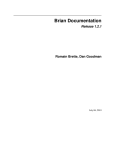
Open Device Pin List Panel
Open the Device Pin List panel, where you enter information on the pins of the microcontroller.
To open the Device Pin List panel, double-click [Project name (Project)] >> [Pin Configurator (Design Tool)] >> [Device
Pin List] in the Project Tree panel.
Figure 2-1. Open Device Pin List Panel
Remarks 1.
If an unsupported microcontroller is defined in the project for Pin Configurator, then "[Pin Configurator
(Design Tool)] node" will hide under [Project name (Project)] in the Project Tree panel.
2.
The Device Pin List panel consists of three tabs. Selecting one of the tabs changes the order in which
"information on each pin of the microcontroller" is displayed.
- [Pin Number] tab
Information on each pin of the microcontroller is displayed in the order of pin number.
- [Macro] tab
Information on each pin of the microcontroller is displayed in the order it was grouped into peripheral
functions.
- [External Peripheral] tab
Information about the pins connected to external peripherals is displayed in order grouped at the
external-peripheral component level.
R20UT2684EJ0100 Rev.1.00
Sep 01, 2013
Page 10 of 480
CubeSuite+ V2.01.00
2.2.1
CHAPTER 2 FUNCTIONS (Pin Configurator)
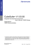
Select item
The Pin Configurator is used to select items to be displayed in the device pin list using the
button in the upper left
corner of the device pin list.
To select the item to be displayed, use the Column Chooser dialog box that opens by pressing the
button in the
upper left corner of the device pin list.
Figure 2-2. Select Item
Remark
To select the item to be displayed, check the check box that corresponds to the item.
Table 2-1. Select Item
Checked
Displays the selected item in the device pin list.
Not checked
Hides the selected item in the device pin list.
R20UT2684EJ0100 Rev.1.00
Sep 01, 2013
Page 11 of 480
CubeSuite+ V2.01.00
2.2.2
CHAPTER 2 FUNCTIONS (Pin Configurator)
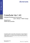
Change display order
In Pin Configurator, you can change the display order of columns in the device pin list (move columns) by dragging and
dropping columns.
Figure 2-3. Change Display Order
Remark
To change the display order, click the
button in the upper left of the device pin list. The Column Chooser
dialog box opens. Drag an item displayed in the dialog's select Items to display area, and drop it to the
desired destination in the device pin list. This will change the display order.
R20UT2684EJ0100 Rev.1.00
Sep 01, 2013
Page 12 of 480
CubeSuite+ V2.01.00
2.2.3
CHAPTER 2 FUNCTIONS (Pin Configurator)
Add column
The Pin Configurator is used to add the "user's own column" to the device pin list using the [New Column...] button in
the Column Chooser dialog box that opens by pressing the
button in the upper left corner of the device pin list.
To add a column, use the New Column dialog box that opens by pressing the [New Column...] button in the Column
Chooser dialog box.
Figure 2-4. Add Column
Remark
2.2.4
On the device pin list, adding columns to the first level of [Macro] tab, [External Peripheral] tab is restricted.
Delete column
The Pin Configurator is used to delete the "user's own column" from the device pin list using the [Delete Column] button
in the Column Chooser dialog box that opens by pressing the
button in the upper left corner of the device pin list.
To delete a column, select the column you want to delete in the displayed item selection area of the Column Chooser
dialog box, and press the [Delete Column] button.
Figure 2-5. Delete Column
Remark
You can only delete the column which you added using the New Column dialog box.
R20UT2684EJ0100 Rev.1.00
Sep 01, 2013
Page 13 of 480
CubeSuite+ V2.01.00
2.3
CHAPTER 2 FUNCTIONS (Pin Configurator)
Open Device Top View Panel
Open the Device Top View panel, where you can confirm the information entered for the pins of the microcontroller.
To open the Device Top View panel, double-click [Project name (Project)] >> [Pin Configurator (Design Tool)] >>
[Device Top View] in the Project Tree panel.
Figure 2-6. Open Device Top View Panel
Remark
In the Property panel, on the [Pin Configurator Settings] tab, if "BGA" is selected for the Package type, then
Device Top View panel cannot be opened.
R20UT2684EJ0100 Rev.1.00
Sep 01, 2013
Page 14 of 480
CubeSuite+ V2.01.00
2.3.1
CHAPTER 2 FUNCTIONS (Pin Configurator)
Select shape of microcontroller
Select the shape of the microcontroller displayed in the Device Top View panel which is opened as described in "2.3
Open Device Top View Panel".
To select the shape of the microcontroller, click [Pin Configurator Settings] tab >> [Package] >> [Package type] in the
Property panel and select the desired shape.
Figure 2-7. Select Shape of Microcontroller
Remark
Selection of the shape of the microcontroller is made using the order name (such as GC and GF).
R20UT2684EJ0100 Rev.1.00
Sep 01, 2013
Page 15 of 480
CubeSuite+ V2.01.00
2.3.2
CHAPTER 2 FUNCTIONS (Pin Configurator)
Select color
Select the colors used to distinguish the type of pins (power pins, special pins, unused pins, etc.) whose information is
displayed in the Device Top View panel which is opened as described in "2.3 Open Device Top View Panel".
To select the color to be displayed, click [Device Top View Settings] tab >> [Color] in the Property panel and select the
color.
Figure 2-8. Select Color
Remark
Select the colors to be displayed for the following eight types of items.
Table 2-2. Select Color
Item
Power pins
Outline
Selects the display color for power pins (pins whose use is
limited to power).
Special pins
Selects the display color for special pins (pins with specified
uses).
Unused pins
Selects the display color for unused pins (dual-use pins with no
use set in the Device Pin List panel).
Used pins
Selects the display color for used pins (dual-use pins with a use
set in the Device Pin List panel).
Device
Selects the display color of the microcontroller.
Highlight color for a selected pin
Selects the background color of a pin selected in the Device
Pin List panel, on the [Pin Number] tab.
R20UT2684EJ0100 Rev.1.00
Sep 01, 2013
Page 16 of 480
CubeSuite+ V2.01.00
CHAPTER 2 FUNCTIONS (Pin Configurator)
Item
Highlight color for macro pins
Outline
Selects the background color of pins selected in the Device Pin
List panel, on the [Macro] tab.
Highlight color for external periph-
Selects the background color of pins selected in the Device Pin
eral pins
List panel, on the [External Peripheral] tab.
R20UT2684EJ0100 Rev.1.00
Sep 01, 2013
Page 17 of 480
CubeSuite+ V2.01.00
2.3.3
CHAPTER 2 FUNCTIONS (Pin Configurator)
Select popup information
Select the type of information that popups when you move the mouse cursor over each pin in the Device Top View
panel which is opened as described in "2.3 Open Device Top View Panel".
To select the popup information, click [Device Top View Settings] tab >> [Tool Tip] >> [Tool tip] in the Property panel and
select the desired type of information.
Figure 2-9. Select Popup Information
Remark
Popup information is selected from the following four types.
Table 2-3. Select Popup Information
Popup Information
Display all
Outline
Displays the "Description", "Recommend Connection for
Unused", and "Attention" strings for the device pin list.
Description / recommended con-
Displays the "Description", and "Recommend Connection for
nection for unused pin only
Unused" strings for the device pin list.
Attention only
Displays the "Attention" string for the device pin list.
Not display
Hides tooltips when the mouse cursor hovers over a pin.
R20UT2684EJ0100 Rev.1.00
Sep 01, 2013
Page 18 of 480
CubeSuite+ V2.01.00
2.3.4
CHAPTER 2 FUNCTIONS (Pin Configurator)
Select additional information
Select the type of information to display in Pin area, in the Device Top View panel opened in "2.3 Open Device Top
View Panel".
Note that additional information is selected from the Property panel, on the [Device Top View Settings] tab, by selecting
the corresponding information under [Pin Name Display].
Figure 2-10. Select Additional Information
Remarks 1.
Select one of the following two types for Define name (whether to display the "Define Name" string of
the Device Pin List in appended format).
Display
Displays the "Define Name" string of the device pin list in appended
format.
Not display
2.
Hides the "Define Name" string of the device pin list.
Select one of the following two types for Pin function (whether to display it whether or not a function is
selected for "Function" on the Device Pin List).
Display all
Displays functions selected via the device pin list's "Function" feature in
parentheses.
Selected function only
Only display functions selected via the device pin list's "Function"
feature in the device top view.
R20UT2684EJ0100 Rev.1.00
Sep 01, 2013
Page 19 of 480
CubeSuite+ V2.01.00
2.4
CHAPTER 2 FUNCTIONS (Pin Configurator)
Enter Information
Enter information on the pins of the microcontroller in the Device Pin List panel which is opened as described in "2.2
Open Device Pin List Panel".
Remarks 1.
You cannot add information in the "Pin Number" column, "Pin Name" column, "Description" column,
"Recommend Connection for Unused" column and "Attention" column because they contain fixed information.
2.
If the "Free" in the "Function" column is changed to a specific pin name, color of the corresponding pin
in the Device Top View panel changes from the "color representing the unused pins" to the "color representing the used pins" selected by clicking [Device Top View Settings] tab >> [Color] in the Property
panel.
Figure 2-11. Change in Displayed Color
R20UT2684EJ0100 Rev.1.00
Sep 01, 2013
Page 20 of 480
CubeSuite+ V2.01.00
2.5
CHAPTER 2 FUNCTIONS (Pin Configurator)
Output Report Files
Output report files (files containing information configured using Pin Configurator: device pin list and device top view) to
the specified folder.
2.5.1
Output device pin list
Select [File] menu >> [Save Pin List As...] to output a report file (a file containing information configured using Pin Configurator: device pin list).
The destination folder for the device pin list is specified in the Save As dialog box which opens by selecting [File] menu
>> [Save Pin List As ...].
Figure 2-12. Output Device Pin List
Remarks 1.
If a device pin list has been already output, that list will be overwritten by selecting [File] menu >> [Save
Pin List].
2.
The output format for the device pin list is limited to Microsoft Office Excel Book.
R20UT2684EJ0100 Rev.1.00
Sep 01, 2013
Page 21 of 480
CubeSuite+ V2.01.00
2.5.2
CHAPTER 2 FUNCTIONS (Pin Configurator)
Output device top view
Select [File] menu >> [Save Top View As...] to output a report file (a file containing information configured using Pin
Configurator: device top view).
The destination folder for the device top view is specified in the Save As dialog box which opens by selecting [File]
menu >> [Save Top View As ...].
Figure 2-13. Output Device Top View
Remark
If a device top view has been already output, that view will be overwritten by selecting [File] menu >> [Save
Top View].
R20UT2684EJ0100 Rev.1.00
Sep 01, 2013
Page 22 of 480
CubeSuite+ V2.01.00
CHAPTER 3 FUNCTIONS (Code Generator)
CHAPTER 3 FUNCTIONS (Code Generator)
This chapter describes the key functions provided by the design tool (Code Generator) along with operation procedures.
Remark
In this chapter, an example where an RL78/L13 (ROM: 128KB) R5F10/WMG(80pin) is the target device is
used to explain the key functions.
3.1
Overview
The Code Generator outputs source code (device driver programs) based on information selected/entered on CubeSuite+ panels that is needed to control the peripheral functions (clock generator, port functions, etc.) provided by the device.
The following sections describe the operation procedures for Code Generator.
(1) Start CubeSuite+
Launch CubeSuite+ from the [Start] menu of Windows.
Remark
See "CubeSuite+ Integrated Development Environment User's Manual: Start" for details on "Start
CubeSuite+".
(2) Create/Open project
Create a new project (that defines a kind of project, device to be used, build tools to be used, etc.) or load an existing project.
Remark
See "CubeSuite+ Integrated Development Environment User's Manual: Start" for details on "Create/
Open project".
(3) Open Peripheral Functions Panel
Open the Peripheral Functions panel used to configure the information necessary to control the peripheral functions (clock generator, port functions, etc.).
(4) Enter Information
Configure the information necessary to control the peripheral functions (clock generator, port functions, etc.) in the
Peripheral Functions panel.
(5) Confirm Source Code
Confirm the source code (device driver program) that reflects the information configured in the Peripheral Functions panel.
(6) Output Source Code
Output the source code (device driver program) to the specified folder.
(7) Output Report Files
Output report files (a file containing information configured using Code Generator and a file containing information
regarding the source code) to the specified folder.
(8) Save project
Save a project.
R20UT2684EJ0100 Rev.1.00
Sep 01, 2013
Page 23 of 480
CubeSuite+ V2.01.00
Remark
CHAPTER 3 FUNCTIONS (Code Generator)
See "CubeSuite+ Integrated Development Environment User's Manual: Start" for details on "Save
project".
3.2
Open Peripheral Functions Panel
The Peripheral Functions panel is opened to set the information necessary to control the peripheral functions (clock
generator, pin functions, etc.) provided in the device.
To open the Peripheral Functions panel, double-click [Project name (Project)] >> [Code Generator (Design Tool)] >>
[Peripheral Functions] (>> Peripheral function node) in the Project Tree panel.
Figure 3-1. Open Peripheral Functions Panel
Remark
If an unsupported device is defined in the project for Code Generator, then "[Code Generator (Design Tool)]
node" will hide under [Project name (Project)] in the Project Tree panel.
R20UT2684EJ0100 Rev.1.00
Sep 01, 2013
Page 24 of 480
CubeSuite+ V2.01.00
3.3
CHAPTER 3 FUNCTIONS (Code Generator)
Enter Information
Configure the information necessary to control the peripheral functions (clock generator, port functions, etc.) in the
information setting area of the Peripheral Functions panel which is opened as described in "3.2 Open Peripheral Functions Panel".
Remark
When controlling multiple peripheral functions, repeat the procedures described in "3.2 Open Peripheral
Functions Panel" through "3.3 Enter Information".
3.3.1
Input rule
Following is the rules for input to the Peripheral Functions panel.
(1) Character set
Character sets that are allowed to input are as follows.
Table 3-1. List of Character Set
Character Set
ASCII
Outline
1-byte alphabet, number, symbol
Shift-JIS
2-byte alphabet, number, symbol, Hiragana, Katakana, Kanji and 1-byte Katakana
EUC-JP
2-byte alphabet, number, symbol, Hiragana, Katakana, Kanji and 1-byte Katakana
UTF-8
2-byte alphabet, number, symbol, Hiragana, Katakana, Kanji (include Chinese
character) and 1-byte Katakana
(2) Number
Notations allowed when entering numbers are as follows.
Table 3-2. List of Notation
Notation
Decimal number
Outline
A numeric value that starts with a number between 1 and 9 and followed by
numbers between 0 and 9, and the numeric value 0
Hex number
A numeric value that starts with 0x and followed by a combination of numbers
from 0 to 9 and characters from A to F (characters are not case sensitive)
R20UT2684EJ0100 Rev.1.00
Sep 01, 2013
Page 25 of 480
CubeSuite+ V2.01.00
3.3.2
CHAPTER 3 FUNCTIONS (Code Generator)
Icon indicating incorrect entry
When performing code generation, if you enter an invalid string in the Peripheral Functions panel, or a required input is
missing, then a
icon displays next to the incorrect input, and the text is displayed in red to warn that there is a problem
with the input.
Remark
If the mouse cursor is moved over the
icon, information regarding the string that should be entered (tips
for correcting the entry) popups.
Figure 3-2. Icon Indicating Incorrect Entry
R20UT2684EJ0100 Rev.1.00
Sep 01, 2013
Page 26 of 480
CubeSuite+ V2.01.00
3.3.3
CHAPTER 3 FUNCTIONS (Code Generator)
Icon indicating pin conflict
If a conflict occurs between the pins while setting various peripheral functions in the Peripheral Functions panel, the
icon is displayed at the location where the conflict occurs to warn the user of a conflict between the pins.
Remark
If the mouse cursor is moved over the
icon, information regarding the conflict between the pins (tips for
avoiding the conflict) popups.
Figure 3-3. Icon Indicating Pin Conflict
R20UT2684EJ0100 Rev.1.00
Sep 01, 2013
Page 27 of 480
CubeSuite+ V2.01.00
3.4
CHAPTER 3 FUNCTIONS (Code Generator)
Confirm Source Code
Confirm the source code (device driver program) that reflects the information configured as described in "3.3 Enter
Information".
To confirm the source code, use the Code Preview panel that opens by double-clicking [Project name (Project)] >>
[Code Generator (Design Tool)] >> [Code Preview] >> Peripheral function node >> Source code node (>> API function
node) in the Project Tree panel.
Figure 3-4. Confirm Source Code
Remarks 1.
You can change the source code to be displayed by selecting the source file name or API function
name in the Project Tree panel.
2.
The following table displays the meaning of the color of the source code text displayed in the Code Preview panel.
Table 3-3. Color of Source Code
Color
Outline
Green
Comment
Blue
Reserved word for C compiler
Red
Numeric value
Black
Code section
Gray
File name
3.
You cannot edit the source code within the Code Preview panel.
4.
For some of the API functions, values such as the register value are calculated and finalized when the
source code is generated (when the
button on the Peripheral Functions panel is
pressed). For this reason, the source code displayed in this panel may not be the same as that would
actually be generated.
R20UT2684EJ0100 Rev.1.00
Sep 01, 2013
Page 28 of 480
CubeSuite+ V2.01.00
3.5
CHAPTER 3 FUNCTIONS (Code Generator)
Output Source Code
Output the source code (device driver program) by pressing the
button on the Peripheral Func-
tions panel.
The destination folder for the source code is specified by clicking [Code Generator Setting] tab >> [Generate File Mode]
>> [Output folder] in the Property panel.
Figure 3-5. Output Source Code
Remark
In order to both output source files and add them to the project (display the corresponding source file names
in the Project Tree panel) when you click the
button, you must open the Property
panel, and under [Code Generator Setting] tab >> [Generate File Mode] >> [Register files], specify
"Register the generated files to the project".
Figure 3-6. Configure Whether to Register
R20UT2684EJ0100 Rev.1.00
Sep 01, 2013
Page 29 of 480
CubeSuite+ V2.01.00
3.5.1
CHAPTER 3 FUNCTIONS (Code Generator)
Set whether or not to generate source code
You can set the type of output API functions (all API functions or only initialization API functions) by selecting [Output
all API functions according to the setting/Output only initialization API function] from [Code Generator Setting] tab >>
[Generate File Mode] >> [API output control] in the Property panel.
Figure 3-7. Setting That Determines Type of API Functions
In the Code Generator, select [Project name (Project)] >> [Code Generator (Design Tool)] >> [Code Preview] >>
Peripheral function node >> Source code node >> API function node in the Project Tree panel. "Setting That Determines
Whether or Not to Generate Source Code" can be set in units of API functions by selecting "Generate Code/Not Generate
Code" from the context menu, which is displayed by right clicking the mouse.
Figure 3-8. Setting That Determines Whether or Not to Generate Source Code
R20UT2684EJ0100 Rev.1.00
Sep 01, 2013
Page 30 of 480
CubeSuite+ V2.01.00
Remark
CHAPTER 3 FUNCTIONS (Code Generator)
Setting That Determines Whether or Not to Generate Source Code" can be confirmed by the types of icons
that are displayed immediately to the left of the API function nodes.
Table 3-4. Setting That Determines Whether or Not to Generate Source Code
Type of Icon
Outline
Source code for the currently selected API function is generated.
If this icon is displayed next to the API function, the corresponding source code must be generated (it is impossible to change
the icon to
).
Source code for the currently selected API function is generated.
Source code for the currently selected API function is not generated.
3.5.2
Change file name
In the Code Generator, select [Project name (Project)] >> [Code Generator (Design Tool)] >> [Code Preview] >>
Peripheral function node >> Source code node in the Project Tree panel. The name of the file can be changed by selecting "Rename" from the context menu, which is displayed by right clicking the mouse.
Figure 3-9. Change File Name
Remark
To restore the default file name defined by the Code Generator, select [Default] from the context menu.
R20UT2684EJ0100 Rev.1.00
Sep 01, 2013
Page 31 of 480
CubeSuite+ V2.01.00
3.5.3
CHAPTER 3 FUNCTIONS (Code Generator)
Change API function name
In the Code Generator, select [Project name (Project)] >> [Code Generator (Design Tool)] >> [Code Preview] >>
Peripheral function node >> Source code node >> API function node in the Project Tree panel. The name of the API function can be changed by selecting "Rename" from the context menu, which is displayed by right clicking the mouse.
Figure 3-10. Change API Function Name
Remarks 1.
To restore the default name of the API function defined by the Code Generator, select [Default] from
the context menu.
2.
Some API functions (main, etc.) can not be changed the API function name.
R20UT2684EJ0100 Rev.1.00
Sep 01, 2013
Page 32 of 480
CubeSuite+ V2.01.00
3.5.4
CHAPTER 3 FUNCTIONS (Code Generator)
Change output mode
The Code Generator is used to change the output mode (Do nothing if file exists, Merge file, Overwrite file) for the
source code by selecting [Code Generator Setting] tab >> [Generate File Mode] >> [File generation control] in the Property panel.
Figure 3-11. Change Output Mode
The output mode is selected from the following three types.
Table 3-5. Output Mode of Source Code
Output Mode
Do nothing if file exists
Merge file
Outline
If a file with the same name exists, a new file will not be output.
If a file with the same name exists, a new file is merged with the existing file.
Only the section between "/* Start user code ... . Do not edit comment generated here */" and "/*
End user code. Do not edit comment generated here */" will be merged.
Overwrite file
Remark
If a file with the same name exists, the existing file is overwritten by a new file.
Note that if the [Merge file] option is selected, the number of left braces ("{") and right braces ("}") must
match in the parts to be merged. When the numbers do not match, processing for correct merging is not
possible.
R20UT2684EJ0100 Rev.1.00
Sep 01, 2013
Page 33 of 480
CubeSuite+ V2.01.00
3.5.5
CHAPTER 3 FUNCTIONS (Code Generator)
Change output destination folder
The Code Generator is used to change the output destination folder for the source code by selecting [Code Generator
Setting] tab >> [Generate File Mode] >> [Output folder] in the Property panel.
Figure 3-12. Change Output Destination Folder
R20UT2684EJ0100 Rev.1.00
Sep 01, 2013
Page 34 of 480
CubeSuite+ V2.01.00
3.6
CHAPTER 3 FUNCTIONS (Code Generator)
Output Report Files
Output report files (a file containing information configured using Code Generator and a file containing information
regarding the source code) by first activating the Peripheral Functions panel or Code Preview panel, then selecting [File]
menu >> [Save Code Generator Report].
The destination folder for the report file is specified by clicking [Code Generator Setting] tab >> [Generate File Mode]
>> [Output folder] in the Property panel.
Remarks 1.
You can only use "Function" or "Macro" as a name of the report file.
See "3.6.1 Change output format" for details on the output format.
Table 3-6. Output Report Files
File Name
Function.xxx
Outline
A file that contains the information regarding the
source code
Macro.xxx
A file that contains the information configured using
Code Generator
2.
The output mode of the report file is defined in "Overwrite file".
Figure 3-13. Output Example of Report File "Function" (HTML File)
R20UT2684EJ0100 Rev.1.00
Sep 01, 2013
Page 35 of 480
CubeSuite+ V2.01.00
CHAPTER 3 FUNCTIONS (Code Generator)
Figure 3-14. Output Example of Report File "Macro" (HTML File)
R20UT2684EJ0100 Rev.1.00
Sep 01, 2013
Page 36 of 480
CubeSuite+ V2.01.00
3.6.1
CHAPTER 3 FUNCTIONS (Code Generator)
Change output format
The Code Generator is used to change the output format (HTML file or CSV file) of the report file by selecting [Code
Generator Setting] tab >> [Generate File Mode] >> [Report type] in the Property panel.
Figure 3-15. Change Output Format
Remark
The output format of the report file is selected from the two types shown below.
Table 3-7. Output Format of Report File
Report Type
Outline
HTML file
Outputs in the HTML format.
CSV file
Outputs in the CSV format.
R20UT2684EJ0100 Rev.1.00
Sep 01, 2013
Page 37 of 480
CubeSuite+ V2.01.00
3.6.2
CHAPTER 3 FUNCTIONS (Code Generator)
Change output destination folder
The Code Generator is used to change the output destination folder for the report file by selecting [Code Generator
Setting] tab >> [Generate File Mode] >> [Output folder] in the Property panel.
Figure 3-16. Change Output Destination Folder
R20UT2684EJ0100 Rev.1.00
Sep 01, 2013
Page 38 of 480
CubeSuite+ V2.01.00
APPENDIX A WINDOW REFERENCE
APPENDIX A WINDOW REFERENCE
This appendix explains in detail the functions of the windows, panels and dialog boxes of the design tool.
A.1
Description
The design tool has the following windows, panels and dialog boxes.
Table A-1. Window/Panel/Dialog Box List
Window/Panel/Dialog Box Name
Main window
Function
This is the first window to open when CubeSuite+ is launched. This window is used to
operate various components (design tool, build tool, etc.) provided by CubeSuite+.
Project Tree panel
This panel displays the components of the project (microcontroller, design tool, build
tool, etc.) in a tree structure.
Property panel
This panel allows you to view the information on and change the setting for the node
selected in the Project Tree panel.
Device Pin List panel
This panel allows you to enter information on each pin of the microcontroller.
Device Top View panel
This panel displays the information entered in the Device Pin List panel.
Peripheral Functions panel
This panel allows you to configure the information necessary to control the peripheral
functions (clock generator, port functions, etc.) provided.
Code Preview panel
This panel allows you to confirm the source code in accord with the settings of the
Peripheral Functions panel.
Output panel
This panel displays operation logs for various components (design tool, build tool, etc.)
provided by CubeSuite+.
Column Chooser dialog box
This dialog box allows you to choose whether or not to display the item listed in this
dialog box in the device pin list, and add columns to or delete columns from the device
pin list.
New Column dialog box
This dialog box allows you to add your own column to the device pin list.
Save As dialog box
This dialog box allows you to name and save a file.
R20UT2684EJ0100 Rev.1.00
Sep 01, 2013
Page 39 of 480
CubeSuite+ V2.01.00
APPENDIX A WINDOW REFERENCE
Main window
This is the first window to open when CubeSuite+ is launched. This window is used to operate various components
(design tool, build tool, etc.) provided by CubeSuite+.
Figure A-1. Main Window
(1)
(2)
The following items are explained here.
- [How to open]
- [Description of each area]
[How to open]
- From the [start] menu, select [All Programs] >> [Renesas Electronics CubeSuite+] >>[CubeSuite+].
[Description of each area]
(1) Menu bar
This area consists of the following menu items.
(a) [File] menu
Save Pin List
Device Pin List panel-dedicated item
Saves a report file (a file containing information configured using Pin
Configurator: device pin list) overwriting the existing file.
R20UT2684EJ0100 Rev.1.00
Sep 01, 2013
Page 40 of 480
CubeSuite+ V2.01.00
Save Pin List As...
APPENDIX A WINDOW REFERENCE
Device Pin List panel-dedicated item
Opens the Save As dialog box for naming and saving a report file (a file
containing information configured using Pin Configurator: device pin list).
Save Top View
Device Top View panel-dedicated item
Saves a report file (a file containing information configured using Pin
Configurator: device top view) overwriting the existing file.
Save Top View As...
Device Top View panel-dedicated item
Opens the Save As dialog box for naming and saving a report file (a file
containing information configured using Pin Configurator: device top view).
Save Code Generator Report
Peripheral Functions panel/Code Preview panel-dedicated item
Outputs report files (a file containing information configured using Code Generator and a file containing information regarding the source code).
- The output format for the report file (either HTML file or CSV file) is selected
by clicking [Code Generator Setting] tab >> [Generate File Mode] >> [Report
type] in the Property panel.
- The destination folder for the report file is specified by clicking [Code Generator Setting] tab >> [Generate File Mode] >> [Output folder] in the Property
panel.
Save Output-Tab Name
Output panel-dedicated item
Saves the message corresponding to the specified tab overwriting the existing
file.
Save Output-Tab Name As...
Output panel-dedicated item
Opens the Save As dialog box for naming and saving the message corresponding to the specified tab.
(b) [Edit] menu
Undo
Property panel-dedicated item
Cancels the effect of an edit operation to restore the previous state.
Cut
Property panel-dedicated item
Sends the character string or lines selected with range selection to the clipboard and deletes them.
Copy
Property panel/Output panel-dedicated item
Sends the character string or lines selected with range selection to the clipboard.
Paste
Property panel-dedicated item
Inserts the contents of the clipboard at the caret position.
Delete
Property panel-dedicated item
Deletes the character string or the lines selected with the range selection.
Select All
Property panel/Output panel-dedicated item
Selects all the strings displayed in the item being edited or all the strings displayed in the Message area.
Search...
Device Pin List panel/Code Preview panel/Output panel-dedicated item
Opens the Search and Replace dialog box for searching strings with the [Quick
Search] tab selected.
Replace...
Output panel-dedicated item
Opens the Search and Replace dialog box for replacing strings with the [Whole
Replace] tab selected.
R20UT2684EJ0100 Rev.1.00
Sep 01, 2013
Page 41 of 480
CubeSuite+ V2.01.00
APPENDIX A WINDOW REFERENCE
(c) [View] menu
Project Tree
Project Tree panel-dedicated item
Opens the Project Tree panel.
Property
Property panel-dedicated item
Opens the Property panel.
Output
Output panel-dedicated item
Opens the Output panel.
Pin Configurator
The cascading menu shown below is displayed.
Device Pin List
Device Pin List panel-dedicated item
Opens the Device Pin List panel.
Device Top View
Device Top View panel-dedicated item
Opens the Device Top View panel.
Code Generator 2
The cascading menu shown below is displayed.
Peripheral Functions
Peripheral Functions panel-dedicated item
Opens the Peripheral Functions panel.
Code Preview
Code Preview panel-dedicated item
Opens the Code Preview panel.
(d) [Help] menu
Open Help for Project Tree Panel
Project Tree panel-dedicated item
Displays the help of Project Tree panel.
Open Help for Property Panel
Property panel-dedicated item
Displays the help of Property panel.
Open Help for Device Pin List
Device Pin List panel-dedicated item
Panel
Displays the help of Device Pin List panel.
Open Help for Device Top View
Device Top View panel-dedicated item
Panel
Displays the help of Device Top View panel.
Open Help for [Code Genera-
Peripheral Functions panel-dedicated item
tor]panel
Displays the help of Peripheral Functions panel.
Open Help for [Code Generator
Code Preview panel-dedicated item
Preview]panel
Displays the help of Code Preview panel.
Open Help for Output Panel
Output panel-dedicated item
Displays the help of Output panel.
(2) Panel display area
This area consists of multiple panels, each dedicated to a different purpose.
See the following sections for details on this area.
- Project Tree panel
- Property panel
- Device Pin List panel
- Device Top View panel
- Peripheral Functions panel
- Code Preview panel
R20UT2684EJ0100 Rev.1.00
Sep 01, 2013
Page 42 of 480
CubeSuite+ V2.01.00
APPENDIX A WINDOW REFERENCE
- Output panel
R20UT2684EJ0100 Rev.1.00
Sep 01, 2013
Page 43 of 480
CubeSuite+ V2.01.00
APPENDIX A WINDOW REFERENCE
Project Tree panel
This panel displays components of the project (microcontroller, design tool, build tool, etc.) in a tree structure.
Figure A-2. Project Tree Panel
(1)
The following items are explained here.
- [How to open]
- [Description of each area]
- [Context menu]
[How to open]
- From the [View] menu, select [Project Tree].
[Description of each area]
(1) Project tree area
This area displays components of the project (microcontroller, design tool, build tool, etc.) in a tree structure.
(a) Pin Configurator (Design Tool)
This node consists of the following pin nodes.
Device Pin List
Opens the Device Pin List panel for entering information on the pins of the
microcontroller.
Device Top View
Opens the Device Top View panel that displays the information entered in the
Device Pin List panel.
(b) Code Generator (Design Tool)
The sub-nodes of this node are [Peripheral Functions] and [Code Preview].
<1> [Peripheral Functions]
The sub-node of this node is the peripheral function node for the peripheral functions (clock generator,
port functions, etc.) supported by the target device.
R20UT2684EJ0100 Rev.1.00
Sep 01, 2013
Page 44 of 480
CubeSuite+ V2.01.00
APPENDIX A WINDOW REFERENCE
Peripheral function node
Double-click on a peripheral function node or press the [Enter] key after
selecting a peripheral function node to open the Peripheral Functions
panel, which is used to make settings for control of the corresponding
peripheral function.
Icons that are displayed immediately to the left of each peripheral function node have the meanings
listed below.
Operation in the corresponding Peripheral Functions panel has been carried out.
Operation in the corresponding Peripheral Functions panel has not been
carried out.
,
The problem occurs on the settings became the manipulation to the
other peripheral function node influences.
<2> [Code Preview]
The sub-node of this node is the peripheral function node for the peripheral functions (clock generator,
port functions, etc.) supported by the target device.
Peripheral function node
Double-click on a source code node/API function node in the level of the
hierarchy below this node or select a source code node/API function
node and press the [Enter] key to open the Code Preview panel, which is
used to confirm that the source code corresponds to the settings in the
Peripheral Functions panel.
Icons that are displayed immediately to the left of each peripheral function node have the meanings
listed below.
Operation in the corresponding Peripheral Functions panel has been carried out.
Operation in the corresponding Peripheral Functions panel has not been
carried out.
[Context menu]
The following context menu items are displayed by right clicking the mouse.
Return to Reset Value
The default settings of the selected node are restored.
Property
Opens the Property panel corresponding to the selected node.
R20UT2684EJ0100 Rev.1.00
Sep 01, 2013
Page 45 of 480
CubeSuite+ V2.01.00
APPENDIX A WINDOW REFERENCE
Property panel
This panel allows you to view the information on and change the setting for the node selected in the Project Tree panel.
Figure A-3. Property Panel
(1)
(2)
The following items are explained here.
- [How to open]
- [Description of each area]
- [Context menu]
[How to open]
- On the Project Tree panel, select [Project name (Project)] >> [Pin Configurator (Design Tool)], and then select
[Property] from the [View] menu.
- On the Project Tree panel, select [Project name (Project)] >> [Pin Configurator (Design Tool)], and then select
[Property] from the context menu.
- On the Project Tree panel, select [Project name (Project)] >> [Pin Configurator (Design Tool)] >> [Device Pin List],
and then select [Property] from the [View] menu.
- On the Project Tree panel, select [Project name (Project)] >> [Pin Configurator (Design Tool)] >> [Device Pin List],
and then select [Property] from the context menu.
- On the Project Tree panel, select [Project name (Project)] >> [Pin Configurator (Design Tool)] >> [Device Top
View], and then select [Property] from the [View] menu.
- On the Project Tree panel, select [Project name (Project)] >> [Pin Configurator (Design Tool)] >> [Device Top
View], and then select [Property] from the context menu.
- On the Project Tree panel, select [Project name (Project)] >> [Code Generator (Design Tool)], and then select
[Property] from the [View] menu.
- On the Project Tree panel, select [Project name (Project)] >> [Code Generator (Design Tool)], and then select
[Property] from the context menu.
- On the Project Tree panel, select [Project name (Project)] >> [Code Generator (Design Tool)] >> [Peripheral
Functions] (>> Peripheral function node), and then select [Property] from the [View] menu.
- On the Project Tree panel, select [Project name (Project)] >> [Code Generator (Design Tool)] >> [Peripheral
Functions] (>> Peripheral function node), and then select [Property] from the context menu.
- On the Project Tree panel, select [Project name (Project)] >> [Code Generator (Design Tool)] >> [Code Preview]
(>> Peripheral function node >> Source code node >> API function node), and then select [Property] from the
[View] menu.
R20UT2684EJ0100 Rev.1.00
Sep 01, 2013
Page 46 of 480
CubeSuite+ V2.01.00
APPENDIX A WINDOW REFERENCE
- On the Project Tree panel, select [Project name (Project)] >> [Code Generator (Design Tool)] >> [Code Preview]
(>> Peripheral function node >> Source code node >> API function node), and then select [Property] from the
context menu.
Remarks 1.
If this panel is already open, selecting a different [Pin Configurator (Design Tool)] in the Project Tree
panel changes the content displayed accordingly.
2.
If this panel is already open, selecting a different [Device Pin List] in the Project Tree panel changes the
content displayed accordingly.
3.
If this panel is already open, selecting a different [Device Top View] in the Project Tree panel changes
the content displayed accordingly.
4.
If this panel is already open, selecting a different [Code Generator (Design Tool)] in the Project Tree
panel changes the content displayed accordingly.
5.
If this panel is already open, selecting [Peripheral Functions] (>> Peripheral function node) in the
Project Tree panel changes the content displayed to that corresponding to the selected node.
6.
If this panel is already open, selecting [Code Preview] (>> Peripheral function node >> source code
node >> API function node) in the Project Tree panel changes the content displayed to that corresponding to the selected node.
[Description of each area]
(1) Detail information display/change area
This area allows you to view the information on and change the setting for the node selected in the Project Tree
panel.
The content displayed in this area differs depending on the node selected in the Project Tree panel.
The following table displays the meaning of
and
displayed to the left of each category.
Indicates that the items within the category are displayed as a "collapsed view".
Indicates that the items within the category are displayed as an "expanded view".
Remark
To switch between
and
, click this mark or double-click the category name.
(2) Tab selection area
In this panel, following tabs are contained (see the section explaining each tab for details on the display/setting on
the tab).
- [Pin Configurator Settings] tab
- [Device Pin List Information] tab
- [Device Top View Settings] tab
- [Code Generator Setting] tab
- [Peripheral Function Information] tab (Product Information)
- [Peripheral Function Information] tab (Peripheral Function Information)
- [Code Preview Information] tab (Product Information)
- [Code Preview Information] tab (Peripheral Function Information)
- [Code Preview Setting] tab (File Information)
- [Code Preview Setting] tab (Function Information)
[Context menu]
The following context menu items are displayed by right clicking the mouse.
R20UT2684EJ0100 Rev.1.00
Sep 01, 2013
Page 47 of 480
CubeSuite+ V2.01.00
APPENDIX A WINDOW REFERENCE
(1) While the item is being edited
Undo
Cancels the effect of an edit operation to restore the previous state.
Cut
Sends the character string or lines selected with range selection to the clipboard and
deletes them.
Copy
Sends the character string or lines selected with range selection to the clipboard.
Paste
Inserts the contents of the clipboard at the caret position.
Delete
Deletes the character string or the lines selected with the range selection.
Select All
Selects all strings displayed in the item being edited.
(2) While the item is not being edited
Property Reset to Default
The selected items are returned to their default settings.
Property Reset All to Default
All items displayed in this tab are returned to their default settings.
R20UT2684EJ0100 Rev.1.00
Sep 01, 2013
Page 48 of 480
CubeSuite+ V2.01.00
APPENDIX A WINDOW REFERENCE
[Pin Configurator Settings] tab
This tab displays information (Product Information and Package) on the [Pin Configurator (Design Tool)] selected in the
Project Tree panel.
Figure A-4. [Pin Configurator Settings] Tab
(1)
(2)
The following items are explained here.
- [How to open]
- [Description of each area]
[How to open]
- On the Project Tree panel, select [Project name (Project)] >> [Pin Configurator (Design Tool)], and then select
[Property] from the [View] menu.
- On the Project Tree panel, select [Project name (Project)] >> [Pin Configurator (Design Tool)], and then select
[Property] from the context menu.
Remark
If this panel is already open, selecting a different [Pin Configurator (Design Tool)] in the Project Tree panel
changes the content displayed accordingly.
[Description of each area]
(1) [Product Information] category
This area displays product information (Version and Release date) on Pin Configurator.
Version
Displays the version of Pin Configurator (Pin Configurator Plug-in).
Release date
Displays the release date of Pin Configurator (Pin Configurator Plug-in).
(2) [Package] category
Change the shape (Package type) and settings of the microcontroller to display as the device top view in the
Device Top View panel.
Package type
R20UT2684EJ0100 Rev.1.00
Sep 01, 2013
Selects the shape of the microcontroller displayed in the device top view.
Page 49 of 480
CubeSuite+ V2.01.00
APPENDIX A WINDOW REFERENCE
[Device Pin List Information] tab
This tab displays information (Product Information) on the [Device Pin List] selected in the Project Tree panel.
Figure A-5. [Device Pin List Information] Tab
(1)
The following items are explained here.
- [How to open]
- [Description of each area]
[How to open]
- On the Project Tree panel, select [Project name (Project)] >> [Pin Configurator (Design Tool)] >> [Device Pin List],
and then select [Property] from the [View] menu.
- On the Project Tree panel, select [Project name (Project)] >> [Pin Configurator (Design Tool)] >> [Device Pin List],
and then select [Property] from the context menu.
Remark
If this panel is already open, selecting a different [Device Pin List] in the Project Tree panel changes the
content displayed accordingly.
[Description of each area]
(1) [Product Information] category
This area displays product information (Version and Release date) on Pin Configurator.
Version
Displays the version of Pin Configurator (Pin Configurator Plug-in).
Release date
Displays the release date of Pin Configurator (Pin Configurator Plug-in).
R20UT2684EJ0100 Rev.1.00
Sep 01, 2013
Page 50 of 480
CubeSuite+ V2.01.00
APPENDIX A WINDOW REFERENCE
[Device Top View Settings] tab
This tab allows you to view the information (Color, Tool Tip and Pin Name Display) on and change the setting for the
[Device Top View] selected in the Project Tree panel.
Figure A-6. [Device Top View Settings] Tab
(1)
(2)
(3)
The following items are explained here.
- [How to open]
- [Description of each area]
[How to open]
- On the Project Tree panel, select [Project name (Project)] >> [Pin Configurator (Design Tool)] >> [Device Top
View], and then select [Property] from the [View] menu.
- On the Project Tree panel, select [Project name (Project)] >> [Pin Configurator (Design Tool)] >> [Device Top
View], and then select [Property] from the context menu.
Remark
If this panel is already open, selecting a different [Device Top View] in the Project Tree panel changes the
content displayed accordingly.
[Description of each area]
(1) [Color] category
Select the display colors to differentiate the pin groups (Power pins, Special pins, etc.) in the device top view.
Power pins
R20UT2684EJ0100 Rev.1.00
Sep 01, 2013
Selects the display color for power pins (pins whose use is limited to power).
Page 51 of 480
CubeSuite+ V2.01.00
APPENDIX A WINDOW REFERENCE
Special pins
Selects the display color for special pins (pins with specified uses).
Unused pins
Selects the display color for unused pins (dual-use pins with no use set in the
Device Pin List panel).
Used pins
Selects the display color for used pins (dual-use pins with a use set in the Device
Pin List panel).
Device
Selects the display color of the microcontroller.
Highlight color for a selected pin
Selects the background color of a pin selected in the Device Pin List panel, on the
[Pin Number] tab.
Highlight color for macro pins
Selects the background color of pins selected in the Device Pin List panel, on the
[Macro] tab.
Highlight color for external
Selects the background color of pins selected in the Device Pin List panel, on the
peripheral pins
[External Peripheral] tab.
(2) [Tool Tip] category
Select whether to display a tooltip with information about a pin when the mouse cursor is moved over the pin in the
device top view.
Tool tip
Selects whether to display a tooltip with information about a pin when the mouse
cursor is moved over the pin in the device top view panel.
Display all
Displays the "Description", "Recommend Connection
for Unused", and "Attention" strings for the device pin
list.
Description / recommended
Displays the "Description", and "Recommend
connection for unused pin
Connection for Unused" strings for the device pin list.
only
Attention only
Displays the "Attention" string for the device pin list.
Not display
Hides tooltips when the mouse cursor hovers over a
pin.
(3) [Pin Name Display] category
Select whether to display additional information about the pin in the device top view.
Define name
Selects whether to display the "Define Name" string of the device pin list appended
to the pin in the device top view.
Display
Displays the "Define Name" string of the device pin
list in appended format.
Not display
Pin function
Hides the "Define Name" string of the device pin list.
Selects whether to also display unselected functions in the device top view when a
function has been selected from the device pin list's "Function" feature.
Display all
Displays functions selected via the device pin list's
"Function" feature in parentheses.
Selected function only
Only display functions selected via the device pin
list's "Function" feature in the device top view.
R20UT2684EJ0100 Rev.1.00
Sep 01, 2013
Page 52 of 480
CubeSuite+ V2.01.00
APPENDIX A WINDOW REFERENCE
[Code Generator Setting] tab
This tab allows you to view the information (Generate File Mode and Product Information) on and change the setting for
the [Code Generator (Design Tool)] selected in the Project Tree panel.
Figure A-7. [Code Generator Setting] Tab
(1)
(2)
The following items are explained here.
- [How to open]
- [Description of each area]
[How to open]
- On the Project Tree panel, select [Project name (Project)] >> [Code Generator (Design Tool)], and then select
[Property] from the [View] menu.
- On the Project Tree panel, select [Project name (Project)] >> [Code Generator (Design Tool)], and then select
[Property] from the context menu.
Remark
If this panel is already open, selecting a different [Code Generator (Design Tool)] in the Project Tree panel
changes the content displayed accordingly.
[Description of each area]
(1) [Generate File Mode] category
This area allows you to view the information (API output control, Output folder, File generation control, Register
files and Report type) on and change the setting for the [Code Generator (Design Tool)] selected in the Project
Tree panel.
R20UT2684EJ0100 Rev.1.00
Sep 01, 2013
Page 53 of 480
CubeSuite+ V2.01.00
API output control
APPENDIX A WINDOW REFERENCE
Select the type of API functions to be output.
Output all API functions
All API functions for the peripheral functions (clock
according to the setting
generation circuit, voltage detection circuit, etc.) that
is set for use in the Peripheral Functions panel are
output.
Output only initialization
Of the API functions for the peripheral functions
API function
(clock generation circuit, voltage detection circuit,
etc.) that are set for use in the Peripheral Functions
panel, only those relating to initialization are output.
Output folder
File generation control
Inputs the output destination folder.
Click on this option to select the reaction to cases where a file having the same file
name exists when the
button of the Peripheral Functions panel is
clicked.
Do nothing if file exists
If a file with the same name exists, a new file will not
be output.
Merge file
If a file with the same name exists, a new file is
merged with the existing file.
Only the section between "/* Start user code ... . Do
not edit comment generated here */" and "/* End user
code. Do not edit comment generated here */" will be
merged.
Overwrite file
If a file with the same name exists, the existing file is
overwritten by a new file.
Register files
Click on this option to select whether or not to register the output file in the project
when the
Register the generated files
button of the Peripheral Functions panel is clicked.
Registers the file.
to the project
Not register the generated
Does not register the file.
files to the project
Report type
Selects the output format for the report files (two files: Function and Macro) that are
output when [Save Code Generator Report] is selected from the [File] menu.
Remark
HTML file
Outputs the files in the HTML format.
CSV file
Outputs the files in the CSV format.
Note that if the [Merge file] is selected in [File generate control], the number of left braces ("{") and right
braces ("}") must match in the parts to be merged. When the numbers do not match, processing for correct merging is not possible.
(2) [Product Information] category
This area allows you to view the information (Release Date and Version) for the [Code Generator (Design Tool)]
selected in the Project Tree panel.
Release Date
Displays the release date of the Code Generator (Design Tool).
Version
Displays the version number of the Code Generator (Design Tool).
R20UT2684EJ0100 Rev.1.00
Sep 01, 2013
Page 54 of 480
CubeSuite+ V2.01.00
APPENDIX A WINDOW REFERENCE
[Peripheral Function Information] tab (Product Information)
This tab allows you to view the information (Product Information) for the [Peripheral Functions] selected in the Project
Tree panel.
Figure A-8. [Peripheral Function Information] Tab (Product Information)
(1)
The following items are explained here.
- [How to open]
- [Description of each area]
[How to open]
- On the Project Tree panel, select [Project name (Project)] >> [Code Generator (Design Tool)] >> [Peripheral
Functions], and then select [Property] from the [View] menu.
- On the Project Tree panel, select [Project name (Project)] >> [Code Generator (Design Tool)] >> [Peripheral
Functions], and then select [Property] from the context menu.
Remark
If this panel is already open, selecting [Peripheral Functions] in the Project Tree panel changes the content
displayed to that corresponding to the selected node.
[Description of each area]
(1) [Product Information] category
This area allows you to view the information (Release date and Version) for the [Peripheral Functions] selected in
the Project Tree panel.
Displays the release date of the Code Generator (Design Tool).
Release Date
Displays the version number of the Code Generator (Design Tool).
Version
R20UT2684EJ0100 Rev.1.00
Sep 01, 2013
Page 55 of 480
CubeSuite+ V2.01.00
APPENDIX A WINDOW REFERENCE
[Peripheral Function Information] tab (Peripheral Function Information)
This tab allows you to view the information (Peripheral Function Information) for the peripheral function node selected
in the Project Tree panel.
Figure A-9. [Peripheral Function Information] Tab (Peripheral Function Information)
(1)
The following items are explained here.
- [How to open]
- [Description of each area]
[How to open]
- On the Project Tree panel, select [Project name (Project)] >> [Code Generator (Design Tool)] >> [Peripheral
Functions] >> Peripheral function node, and then select [Property] from the [View] menu.
- On the Project Tree panel, select [Project name (Project)] >> [Code Generator (Design Tool)] >> [Peripheral
Functions] >> Peripheral function node, and then select [Property] from the context menu.
Remark
If this panel is already open, selecting peripheral function node in the Project Tree panel changes the content displayed to that corresponding to the selected node.
[Description of each area]
(1) [Peripheral Function Information] category
This area allows you to view the information (Peripheral function name, Peripheral function error and Peripheral
function used) for the peripheral function node selected in the Project Tree panel.
Peripheral function name
Displays the name of the peripheral function.
Peripheral function error
Displays whether or not the settings in the Peripheral Functions panel are correct.
Peripheral function used
No error
Illegal settings have not been detected.
Input error
Illegal settings have been detected.
Indicates whether or not to use the peripheral function.
Note that whether or not a function is to be used depends on the settings in the
Peripheral Functions panel corresponding to the selected node.
R20UT2684EJ0100 Rev.1.00
Sep 01, 2013
Used
The peripheral function is to be used.
No
The peripheral function is not to be used.
Page 56 of 480
CubeSuite+ V2.01.00
APPENDIX A WINDOW REFERENCE
[Code Preview Information] tab (Product Information)
This tab allows you to view the information (Product Information) for the [Code Preview] selected in the Project Tree
panel.
Figure A-10. [Code Preview Information] Tab (Product Information)
(1)
The following items are explained here.
- [How to open]
- [Description of each area]
[How to open]
- On the Project Tree panel, select [Project name (Project)] >> [Code Generator (Design Tool)] >> [Code Preview],
and then select [Property] from the [View] menu.
- On the Project Tree panel, select [Project name (Project)] >> [Code Generator (Design Tool)] >> [Code Preview],
and then select [Property] from the context menu.
Remark
If this panel is already open, selecting [Peripheral Functions] in the Project Tree panel changes the content
displayed to that corresponding to the selected node.
[Description of each area]
(1) [Product Information] category
This area allows you to view the information (Release Date and Version) for the [Code Preview] selected in the
Project Tree panel.
Release Date
Displays the release date of the Code Generator (Design Tool).
Version
Displays the version number of the Code Generator (Design Tool).
R20UT2684EJ0100 Rev.1.00
Sep 01, 2013
Page 57 of 480
CubeSuite+ V2.01.00
APPENDIX A WINDOW REFERENCE
[Code Preview Information] tab (Peripheral Function Information)
This tab allows you to view the information (Peripheral Function Information) for the peripheral function node selected
in the Project Tree panel.
Figure A-11. [Code Preview Information] Tab (Peripheral Function Information)
(1)
The following items are explained here.
- [How to open]
- [Description of each area]
[How to open]
- On the Project Tree panel, select [Project name (Project)] >> [Code Generator (Design Tool)] >> [Code Preview]
>> Peripheral function node, and then select [Property] from the [View] menu.
- On the Project Tree panel, select [Project name (Project)] >> [Code Generator (Design Tool)] >> [Code Preview]
>> Peripheral function node, and then select [Property] from the context menu.
Remark
If this panel is already open, selecting peripheral function node in the Project Tree panel changes the content displayed to that corresponding to the selected node.
[Description of each area]
(1) [Peripheral Function Information] category
This area allows you to view the information (Peripheral function name and Peripheral function used) for the
peripheral function node selected in the Project Tree panel.
Peripheral function name
Displays the name of the peripheral function.
Peripheral function used
Indicates whether or not to use the peripheral function.
Note that whether or not a function is to be used depends on the settings in the
Peripheral Functions panel corresponding to the selected node.
R20UT2684EJ0100 Rev.1.00
Sep 01, 2013
Yes
The peripheral function is to be used.
No
The peripheral function is not to be used.
Page 58 of 480
CubeSuite+ V2.01.00
APPENDIX A WINDOW REFERENCE
[Code Preview Setting] tab (File Information)
This tab allows you to view the information (File Information) on and change the setting for the source code node
selected in the Project Tree panel.
Figure A-12. [Code Preview Setting] Tab (File Information)
(1)
The following items are explained here.
- [How to open]
- [Description of each area]
[How to open]
- On the Project Tree panel, select [Project name (Project)] >> [Code Generator (Design Tool)] >> [Code Preview]
>> Peripheral function node >> Source code node, and then select [Property] from the [View] menu.
- On the Project Tree panel, select [Project name (Project)] >> [Code Generator (Design Tool)] >> [Code Preview]
>> Peripheral function node >> Source code node, and then select [Property] from the context menu.
Remark
If this panel is already open, selecting the source code node in the Project Tree panel changes the content
displayed to that corresponding to the selected node.
[Description of each area]
(1) [File Information] category
This area allows you to view the information (Fine name, File used, Default name and Output folder) on and
change the setting for the source code node selected in the Project Tree panel.
File name
Inputs the name of the file
The name of the file can be changed by selecting [Rename] from the context menu
after selecting the source code node in the Project Tree panel.
File used
Indicates whether or not output to a file is to proceed when the
button in the Peripheral Functions panel is clicked. Note that whether or not this
option is used depends on the settings in the Peripheral Functions panel corresponding to the selected node.
R20UT2684EJ0100 Rev.1.00
Sep 01, 2013
Yes
A file is output.
No
A file is not output.
Page 59 of 480
CubeSuite+ V2.01.00
Default name
APPENDIX A WINDOW REFERENCE
Selects whether or not to restore the default name of the file.
Note that the default name of the file can be restored by selecting [Default] from the
context menu after selecting the source code node in the Project Tree panel.
Output folder
Yes
The default name is restored.
No
The default name is not restored.
Displays the output destination folder.
Note that the output destination folder can be changed by using [Generate File
Mode] >> [Output folder] in the [Code Generator Setting] tab.
R20UT2684EJ0100 Rev.1.00
Sep 01, 2013
Page 60 of 480
CubeSuite+ V2.01.00
APPENDIX A WINDOW REFERENCE
[Code Preview Setting] tab (Function Information)
This tab allows you to view the information (Function Information) on and change the setting for the API function node
selected in the Project Tree panel.
Figure A-13. [Code Preview Setting] Tab (Function Information)
(1)
The following items are explained here.
- [How to open]
- [Description of each area]
[How to open]
- On the Project Tree panel, select [Project name (Project)] >> [Code Generator (Design Tool)] >> [Code Preview]
>> Peripheral function node >> Source code node >> API function node, and then select [Property] from the [View]
menu.
- On the Project Tree panel, select [Project name (Project)] >> [Code Generator (Design Tool)] >> [Code Preview]
>> Peripheral function node >> Source code node >> API function node, and then select [Property] from the
context menu.
Remark
If this panel is already open, selecting the API function node in the Project Tree panel changes the content
displayed to that corresponding to the selected node.
[Description of each area]
(1) [Function Information] category
This area allows you to view the information (Function name, Function used and Default name) on and change the
setting for the API function node selected in the Project Tree panel.
Function name
Inputs the name of the API function.
Note that the name of the API function can be changed by selecting [Rename] from
the context menu after selecting the API function node in the Project Tree panel.
Function used
Selects whether or not to output the API function when the
but-
ton in the Peripheral Functions panel is clicked.
R20UT2684EJ0100 Rev.1.00
Sep 01, 2013
Generated
The API function is output.
Ungenerated
The API function is not output.
Page 61 of 480
CubeSuite+ V2.01.00
Default name
APPENDIX A WINDOW REFERENCE
Selects whether or not to restore the default name of the API function.
Note that the default name of the API function can be restored by selecting [Default]
from the context menu after selecting the source code node in the Project Tree
panel.
R20UT2684EJ0100 Rev.1.00
Sep 01, 2013
Yes
The default name is restored.
No
The default name is not restored.
Page 62 of 480
CubeSuite+ V2.01.00
APPENDIX A WINDOW REFERENCE
Device Pin List panel
This panel allows you to enter information on each pin of the microcontroller.
Remark
The Device pin list area can be zoomed in and out by
in the tool bar, or by operating the mouse
wheel while holding down the [Ctrl] key.
Figure A-14. Device Pin List Panel
(1)
(2)
(3)
The following items are explained here.
- [How to open]
- [Description of each area]
[How to open]
- On the Project Tree panel, double-click [Project name (Project)] >> [Pin Configurator (Design Tool)] >> [Device Pin
List].
- On the Project Tree panel, select [Project name (Project)] >> [Pin Configurator (Design Tool)] >> [Device Pin List],
and then press the [Enter] key.
- From the [View] menu, select [Pin Configurator] >> [Device Pin List].
[Description of each area]
(1) Toolbar
This area consists of the following buttons.
Displays the information in the Device pin list area in an expanded view.
Displays the information in the Device pin list area in a folded view only.
Clicks this button to automatically process the configuration information in the
selected function, I/O, N-ch, and other fields after selecting one of the peripheral
functions displayed in the first level on the [Macro] tab.
Clicks this button to initialize the selected function, I/O, N-ch, and other fields after
selecting one of the peripheral functions displayed in the first level on the [Macro]
tab.
R20UT2684EJ0100 Rev.1.00
Sep 01, 2013
Page 63 of 480
CubeSuite+ V2.01.00
APPENDIX A WINDOW REFERENCE
Clicks this button to create an external peripheral controller from the external peripheral controller information on the [External Peripheral] tab, and display it in the
Device Top View panel.
Clicks this button to delete the information for the external peripheral controller displayed on the [External Peripheral] tab, on the first layer.
Remarks 1.
Click the
button to add the information in question as a choice in the "External Parts" column
of the [Macro] tab and the [Pin Number] tab.
2.
Click the
button to remove the external peripheral component in question from the Device top
view area if the Device Top View panel.
(2) Device pin list area
This area displays the "device pin list" for entering information on the pins of the microcontroller.
(3) Tab selection area
Selecting the tab changes the order in which "information on each pin of the microcontroller" is displayed.
This panel has the following tabs:
- [Pin Number] tab
This tab displays information on each pin of the microcontroller in the order of pin number.
- [Macro] tab
This tab displays information on each pin of the microcontroller in the order it was grouped into peripheral
functions.
- [External Peripheral] tab
This tab displays information about the pins connected to external peripherals in order grouped at the externalperipheral component level.
R20UT2684EJ0100 Rev.1.00
Sep 01, 2013
Page 64 of 480
CubeSuite+ V2.01.00
APPENDIX A WINDOW REFERENCE
[Pin Number] tab
This tab displays information on each pin of the microcontroller in the order of pin number.
Figure A-15. [Pin Number] Tab
(1)
The following items are explained here.
- [How to open]
- [Description of each area]
[How to open]
- On the Project Tree panel, double-click [Project name (Project)] >> [Pin Configurator (Design Tool)] >> [Device Pin
List].
- On the Project Tree panel, select [Project name (Project)] >> [Pin Configurator (Design Tool)] >> [Device Pin List],
and then press the [Enter] key.
- From the [View] menu, select [Pin Configurator] >> [Device Pin List].
[Description of each area]
(1) Device pin list area
This area displays the "device pin list" for entering information on the pins of the microcontroller.
The device pin list in this area is organized in the order of pin number.
The following are the columns comprising the device pin list.
Column Heading
Outline
Pin Number
Displays the pin number of the pin.
Pin Name
This area allows you to select "which function to use" when the pin has more than
one functions.
Function
This area allows you to select "which function to use" when the pin has more than
one functions.
I/O
N-ch
This area allows you to select the I/O mode of the pin.
This area allows you to select "which output mode to apply" when using the pin in
the output mode.
R20UT2684EJ0100 Rev.1.00
Sep 01, 2013
Page 65 of 480
CubeSuite+ V2.01.00
APPENDIX A WINDOW REFERENCE
Column Heading
Define Name
Outline
This area allows you to assign a "user-defined pin name" to the pin.
wITHIN 256 characters can be entered in the [Define Name].
Description
Displays the summary of function of the pin.
Recommend Connection for
Displays instructions on how to handle the pin when it is not used.
Unused
This column displays information only when the "Free" is selected in the "Function"
column.
Attention
Displays the precaution on using the pin.
External Parts
This area is for selecting which external peripheral controller to connect the pin to.
Remarks 1.
You cannot add information in the "Pin Number" column, "Pin Name" column, "Description" column, "Recommend Connection for Unused" column and "Attention" column because they contain
fixed information.
2.
If the "Free" in the "Function" column is changed to a specific pin name, color of the corresponding
pin in the Device Top View panel changes from the "color representing the unused pins" to the
"color representing the used pins" selected by clicking [Device Top View Settings] tab >> [Color] in
the Property panel.
3.
To move columns (change the display order) in the device pin list, drag and drop the desired
column to the desired location.
4.
To add the "user's own column", use the New Column dialog box which opens by pressing the
[New Column...] button in the Column Chooser dialog box which opens by pressing the
button
in the upper left corner of the device pin list.
R20UT2684EJ0100 Rev.1.00
Sep 01, 2013
Page 66 of 480
CubeSuite+ V2.01.00
APPENDIX A WINDOW REFERENCE
[Macro] tab
This tab displays information on each pin of the microcontroller in the order it was grouped into peripheral functions.
Figure A-16. [Macro] Tab
(1)
The following items are explained here.
- [How to open]
- [Description of each area]
[How to open]
- On the Project Tree panel, double-click [Project name (Project)] >> [Pin Configurator (Design Tool)] >> [Device Pin
List].
- On the Project Tree panel, select [Project name (Project)] >> [Pin Configurator (Design Tool)] >> [Device Pin List],
and then press the [Enter] key.
- From the [View] menu, select [Pin Configurator] >> [Device Pin List].
[Description of each area]
(1) Device pin list area
This area displays the "device pin list" for entering information on the pins of the microcontroller.
The device pin list in this area is organized in the order the pins were grouped into peripheral functions.
(a) First layer
The following are the columns comprising the device pin list.
Column Heading
Outline
Macro Name
Displays the name of the peripheral function.
Total
Displays the total number of pins assigned to the peripheral function.
Used
Displays the total number of pins for which the purpose has been set.
Used in Other Macro
Displays the total number of pins for which the purpose has been set by other
peripheral functions.
R20UT2684EJ0100 Rev.1.00
Sep 01, 2013
Page 67 of 480
CubeSuite+ V2.01.00
APPENDIX A WINDOW REFERENCE
(b) Second layer
Column Heading
Outline
Pin Number
Displays the pin number of the pin.
Pin Name
Displays the pin name of the pin.
Function
This area allows you to select "which function to use" when the pin has more
than one functions.
I/O
This area allows you to select the I/O mode of the pin.
N-ch
This area allows you to select "which output mode to apply" when using the
pin in the output mode.
Define Name
This area allows you to assign a "user-defined pin name" to the pin.
Within 256 characters can be entered in the [Define Name].
Description
Displays the summary of function of the pin.
Recommend Connection for
Displays instructions on how to handle the pin when it is not used.
Unused
This column displays information only when the "Free" is selected in the
"Function" column.
Attention
Displays the precaution on using the pin.
External Parts
This area is for selecting which external peripheral controller to connect the
pin to.
Remarks 1.
You cannot add information in the "Macro Name", "Total", "Used", "Used by other function", "Pin
Number", "Pin Name", "Description", "Recommend Connection for Unused" and "Attention" columns because they contain fixed information.
2.
If the "Free" in the "Function" column is changed to a specific pin name, color of the corresponding
pin in the Device Top View panel changes from the "color representing the unused pins" to the
"color representing the used pins" selected by clicking [Device Top View Settings] tab >> [Color] in
the Property panel.
3.
To move columns (change the display order) in the device pin list, drag and drop the desired column to the desired location.
4.
To add the "user's own column", use the New Column dialog box which opens by pressing the
[New Column...] button in the Column Chooser dialog box which opens by pressing the
button
in the upper left corner of the device pin list.
R20UT2684EJ0100 Rev.1.00
Sep 01, 2013
Page 68 of 480
CubeSuite+ V2.01.00
APPENDIX A WINDOW REFERENCE
[External Peripheral] tab
This tab displays information about the pins connected to external peripherals in order grouped at the external-peripheral component level.
Figure A-17. [External Peripheral] Tab
(1)
The following items are explained here.
- [How to open]
- [Description of each area]
[How to open]
- On the Project Tree panel, double-click [Project name (Project)] >> [Pin Configurator (Design Tool)] >> [Device Pin
List].
- On the Project Tree panel, select [Project name (Project)] >> [Pin Configurator (Design Tool)] >> [Device Pin List],
and then press the [Enter] key.
- From the [View] menu, select [Pin Configurator] >> [Device Pin List].
[Description of each area]
(1) Device pin list area
This area displays the "device pin list" for entering information on the pins connected to external peripheral parts.
Note that items in this area's device pin list are sorted by groups at the external peripheral controller level.
(a) First layer
The following are the columns comprising the device pin list.
Column Heading
External Peripheral
Outline
Displays the name of the external peripheral controller.
To change the name, select this field and then press the [F2] key.
Total
Displays the total number of pins allocated for connection with the microcontroller.
(b) Second layer
Column Heading
Outline
Pin Number
Displays the pin number of the pin.
Pin Name
Displays the pin name of the pin.
R20UT2684EJ0100 Rev.1.00
Sep 01, 2013
Page 69 of 480
CubeSuite+ V2.01.00
APPENDIX A WINDOW REFERENCE
Column Heading
Function
Outline
This area allows you to select "which function to use" when the pin has more
than one functions.
I/O
This area allows you to select the I/O mode of the pin.
N-ch
This area allows you to select "which output mode to apply" when using the pin
in the output mode.
Define Name
This area allows you to assign a "user-defined pin name" to the pin.
Within 256 characters can be entered in the [Define Name].
Description
Displays the summary of function of the pin.
Recommend Connection for
Displays instructions on how to handle the pin when it is not used.
Unused
This column displays information only when the "Free" is selected in the "Function" column.
Attention
Remarks 1.
Displays the precaution on using the pin.
You cannot add information in the "External Peripheral Name", "Connected Pins", "Pin Number",
"Pin Name", "Description", "Recommend Connection for Unused" and "Attention" columns
because they contain fixed information.
2.
If the "Free" in the "Function" column is changed to a specific pin name, color of the corresponding
pin in the Device Top View panel changes from the "color representing the unused pins" to the
"color representing the used pins" selected by clicking [Device Top View Settings] tab >> [Color] in
the Property panel.
3.
To move columns (change the display order) in the device pin list, drag and drop the desired column to the desired location.
4.
To add the "user's own column", use the New Column dialog box which opens by pressing the
[New Column...] button in the Column Chooser dialog box which opens by pressing the
button
in the upper left corner of the device pin list.
R20UT2684EJ0100 Rev.1.00
Sep 01, 2013
Page 70 of 480
CubeSuite+ V2.01.00
APPENDIX A WINDOW REFERENCE
Device Top View panel
This panel displays the information entered in the Device Pin List panel.
Remark
The Device top view area can be zoomed in and out by
in the tool bar.
Figure A-18. Device Top View Panel
(1)
(2)
(3)
The following items are explained here.
- [How to open]
- [Description of each area]
- [Context menu]
[How to open]
- On the Project Tree panel, double-click [Project name (Project)] >> [Pin Configurator (Design Tool)] >> [Device Top
View].
- On the Project Tree panel, select [Project name (Project)] >> [Pin Configurator (Design Tool)] >> [Device Top
View], and then press the [Enter] key.
- From the [View] menu, select [Pin Configurator] >> [Device Top View].
Remark
In the Property panel, on the [Pin Configurator Settings] tab >> [Package >> [Package type]], if "BGA" is
selected, then this panel cannot be opened.
[Description of each area]
(1) Toolbar
This area consists of the following buttons.
R20UT2684EJ0100 Rev.1.00
Sep 01, 2013
Page 71 of 480
CubeSuite+ V2.01.00
APPENDIX A WINDOW REFERENCE
Clicks this button to enable changing of the display in the Device top view area by
drag and drop.
By pressing this button, the shape of the mouse cursor in the Device top view area
changes from the arrow to the hand.
Clicks this button to enable moving external peripheral components in the Device
top view area to arbitrary locations, and select pins.
By pressing this button, the shape of the mouse cursor which has changed into the
hand by pressing the
button reverts back to the arrow.
Rotates the content in the Device top view area 90 degrees counter-clockwise.
Rotates the content in the Device top view area 90 degrees clockwise.
Expands or reduces the content in the Device top view area.
(2) [User Define] area
Drag and drop the
button from this area to the Device top view area to creat and display an external peripheral
controller.
(3) Device top view area
This area displays the pin assignment of the microcontroller.
Settings of the pin assignment are displayed using the colors specified by selecting [Device Top View Settings] tab
>> [Color] in the Property panel.
Remark
If the pin name in the diagram is double-clicked, the Device Pin List panel opens and the focus moves
to the clicked pin in the list.
[Context menu]
When you right click on a pin or external peripheral controller in the Device top view area, the following context menu
displays.
(1) When a pin is right clicked
Use as
If the pin has multiple functions, select which function to use.
Connect to External Peripheral
Selects which external peripheral controller to connect the pin to.
(2) When an external peripheral controller is right clocked
Disconnect Pin
Disconnects from the pin.
Delete External Peripheral
Removes the external peripheral controller.
R20UT2684EJ0100 Rev.1.00
Sep 01, 2013
Page 72 of 480
CubeSuite+ V2.01.00
APPENDIX A WINDOW REFERENCE
Peripheral Functions panel
This panel allows you to configure the information necessary to control the peripheral functions (clock generator, port
functions, etc.) provided.
Figure A-19. Peripheral Functions Panel
(1)
(2)
The following items are explained here.
- [How to open]
- [Description of each area]
[How to open]
- On the Project Tree panel, double-click [Project name (Project)] >> [Code Generator (Design Tool)] >> [Peripheral
Functions] (>> Peripheral function node).
- On the Project Tree panel, select [Project name (Project)] >> [Code Generator (Design Tool)] >> [Peripheral
Functions] (>> Peripheral function node), and then press the [Enter] key.
- From the [View] menu >> [Code Generator 2], select [Peripheral Functions].
Remark
If this panel is already open, pressing a different peripheral function button "
,
, etc." changes the
content displayed in the Information setting area accordingly.
R20UT2684EJ0100 Rev.1.00
Sep 01, 2013
Page 73 of 480
CubeSuite+ V2.01.00
APPENDIX A WINDOW REFERENCE
[Description of each area]
(1) Toolbar
This area consists of the following "peripheral function buttons".
When there is peripheral function target microcontroller is not supporting, peripheral functionbutton is not
disokayed.
Outputs the source code (device driver program) to the folder specified by selecting
[Code Generator Setting] tab >> [Generate File Mode] >> [Output folder] in the
Property panel.
,
, etc.
Changes the content displayed in the Information setting area to information
required for controlling peripheral functions.
(2) Information setting area
The content displayed in this area differs depending on the "peripheral function node" or "peripheral function button" selected or pressed when opening this panel.
See user's manual for microcontroller for details on the items to be set.
R20UT2684EJ0100 Rev.1.00
Sep 01, 2013
Page 74 of 480
CubeSuite+ V2.01.00
APPENDIX A WINDOW REFERENCE
Code Preview panel
This panel allows you to confirm the source code in accord with the settings of the Peripheral Functions panel.
Figure A-20. Code Preview Panel
(1)
The following items are explained here.
- [How to open]
- [Description of each area]
- [Context menu]
[How to open]
- On the Project Tree panel, double-click [Project name (Project)] >> [Code Generator (Design Tool)] >> [Code
Preview] >> Peripheral function node >> Source code node (>> API function node).
- On the Project Tree panel, select [Project name (Project)] >> [Code Generator (Design Tool)] >> [Code Preview]
>> Peripheral function node >> Source code node (>> API function mode), and then press the [Enter] key.
- From the [View] menu >> [Code Generator 2], select [Code Preview].
Remark
If this panel is already open, double-clicking the source code node (>> API function node) changes the content displayed in the Source code display area to that corresponding to the selected node.
[Description of each area]
(1) Source code display area
This area allows you to confirm the source code (device driver program) that reflects the information configured in
the Peripheral Functions panel.
The following table displays the meaning of the color of the source code text displayed in this area.
Table A-2. Color of Source Code
Color
Outline
Green
Comment
Blue
Reserved word for C compiler
Red
Numeric value
Black
Code section
R20UT2684EJ0100 Rev.1.00
Sep 01, 2013
Page 75 of 480
CubeSuite+ V2.01.00
APPENDIX A WINDOW REFERENCE
Color
Gray
Outline
File name
Remarks 1.
2.
You cannot edit the source code within this panel.
For some of the API functions, values such as the register value are calculated and finalized when
the source code is generated (when the
button on the Peripheral Functions
panel is pressed). For this reason, the source code displayed in this panel may not be the same as
that would actually be generated.
[Context menu]
The following context menu items are displayed by right clicking the mouse.
Copy
Sends the character string or lines selected with range selection to the clipboard.
Select All
Selects all the messages displayed on the Source code display area.
R20UT2684EJ0100 Rev.1.00
Sep 01, 2013
Page 76 of 480
CubeSuite+ V2.01.00
APPENDIX A WINDOW REFERENCE
Output panel
This panel displays operation logs for various components (design tool, build tool, etc.) provided by CubeSuite+.
The messages are classified by the message origination tool and displayed on the individual tabs.
Remark
The Message area can be zoomed in and out by
in the tool bar, or by operating the mouse
wheel while holding down the [Ctrl] key.
Figure A-21. Output Panel
(1)
(2)
The following items are explained here.
- [How to open]
- [Description of each area]
- [Context menu]
[How to open]
- From the [View] menu, select [Output].
[Description of each area]
(1) Message area
The output messages of each tool are displayed.
Note that the character colors/background colors of the message differ with the type of output message (and
depend on the settings in the [General - Font and Color] category in the Option dialog box).
(2) Tab selection area
Select the tab that indicates the origin of message.
The following tabs are available for the debug tool.
Tab Name
All Messages
Description
Displays operation logs for all components (design tool, build tool, etc.) provided by CubeSuite+ in
order of output.
Code Generator
Display only operation logs for the Code Generator out of those for various components (design tool,
build tool, etc.) provided by CubeSuite+.
Caution
Even if a new message is output on a deselected tab, tab selection will not automatically switch.
In this case, " * " mark will be added in front of the tab name, indicating that a new message has
been output.
[Context menu]
The following context menu items are displayed by right clicking the mouse.
R20UT2684EJ0100 Rev.1.00
Sep 01, 2013
Page 77 of 480
CubeSuite+ V2.01.00
APPENDIX A WINDOW REFERENCE
Copy
Sends the character string or lines selected with range selection to the clipboard.
Select All
Selects all the messages displayed on the Message area.
Clear
Deletes all the messages displayed on the Message area.
Tag Jump
Jumps to the caret line in the editor indicated by the message (file, line, and column).
Open Help for Message
Displays help for the message on the current caret location.
This only applies to warning messages and error messages.
R20UT2684EJ0100 Rev.1.00
Sep 01, 2013
Page 78 of 480
CubeSuite+ V2.01.00
APPENDIX A WINDOW REFERENCE
Column Chooser dialog box
This dialog box allows you to choose whether or not to display the item listed in this dialog box in the device pin list, and
add columns to or delete columns from the device pin list.
Figure A-22. Column Chooser Dialog Box
(1)
(2)
[Function buttons]
The following items are explained here.
- [How to open]
- [Description of each area]
- [Function buttons]
[How to open]
- In the [Pin Number] tab of the Device Pin List panel, click the
- In the [Macro] tab of the Device Pin List panel, click the
button.
button.
- In the [External Peripheral] tab of the Device Pin List panel, click the
button.
[Description of each area]
(1) Operational object selection area
This area allows you to select the device pin list to be configured in this dialog box.
Pin Number
Configures the device pin list corresponding to the [Pin Number] tab.
Macro
Configures the device pin list belonging to the first layer of the [Macro] tab.
Macro - Pin
Configures the device pin list belonging to the second layer of the [Macro] tab.
External Peripheral
Configures the device pin list belonging to the first layer of the [External Peripheral]
tab.
External Peripheral - Pin
Configures the device pin list belonging to the second layer of the [External Peripheral] tab.
R20UT2684EJ0100 Rev.1.00
Sep 01, 2013
Page 79 of 480
CubeSuite+ V2.01.00
APPENDIX A WINDOW REFERENCE
(2) Displayed item selection area
Select whether or not to display the item selected in the Operational object selection area in the device pin list.
Checked
Displays the selected item in the device pin list.
Not checked
Hides the selected item in the device pin list.
[Function buttons]
Button
Function
New Column...
Opens the New Column dialog box for adding columns to the device pin list.
Delete Column
Deletes the selected columns from the device pin list.
You can only delete the column which you added using the New Column dialog box.
Default
Restores the column order to the default settings.
Close
Closes this dialog box.
R20UT2684EJ0100 Rev.1.00
Sep 01, 2013
Page 80 of 480
CubeSuite+ V2.01.00
APPENDIX A WINDOW REFERENCE
New Column dialog box
This dialog box allows you to add your own column to the device pin list.
Figure A-23. New Column Dialog Box
(1)
(2)
[Function buttons]
The following items are explained here.
- [How to open]
- [Description of each area]
- [Function buttons]
[How to open]
- Click the [New Column...] button in the Column Chooser dialog box.
[Description of each area]
(1) [Name]
This area allows you to enter column headings of the columns added to the device pin list.
Witnin 256 characters can be entered in the [Name].
(2) [Type]
Select the input format of the column to add to the device pin list.
Text
Only character strings can be entered in the column.
Cehck box
Adds a column of check boxes.
Whole number
Only integers can be entered in the column.
Real number
Only real numbers can be entered in the column.
Date
Only dates in YYYYMMDD format can be entered in the column.
[Function buttons]
Button
OK
Function
Adds a column that has the column heading specified in the [Name] to the right end of
the device pin list.
Cancel
R20UT2684EJ0100 Rev.1.00
Sep 01, 2013
Ignores the setting and closes this dialog box.
Page 81 of 480
CubeSuite+ V2.01.00
APPENDIX A WINDOW REFERENCE
Save As dialog box
This dialog box allows you to name and save a file.
Figure A-24. Save As Dialog Box
(1)
[Function buttons]
(2)
(3)
(4)
[Function buttons]
The following items are explained here.
- [How to open]
- [Description of each area]
- [Function buttons]
[How to open]
- From the [File] menu, select [Save Output-Tab Name].
- From the [File] menu, select [Save Output-Tab Name As...].
[Description of each area]
(1) Folder location
This is for selection of the output destination folder (folder name).
(2) List of files
This area displays a list of files matching the conditions selected in Folder location and [Save as type].
(3) [File name]
Specify the name of the file (file name).
R20UT2684EJ0100 Rev.1.00
Sep 01, 2013
Page 82 of 480
CubeSuite+ V2.01.00
APPENDIX A WINDOW REFERENCE
(4) [Save as type]
Select the type of the file (file type).
[Function buttons]
Button
Save
Function
Outputs a file having the name specified in the [File name] and [Save as type] to the
folder specified in the Folder location.
Cancel
R20UT2684EJ0100 Rev.1.00
Sep 01, 2013
Ignores the setting and closes this dialog box.
Page 83 of 480
CubeSuite+ V2.01.00
APPENDIX B OUTPUT FILES
APPENDIX B OUTPUT FILES
This appendix describes the files output by the Code Generator.
B.1
Description
Below is a list of output file files by the Code Generator.
Table B-1. Output File List
Peripheral Function
Common
File Name
r_main.c or r_cg_main.c
API Function Name
main
R_MAIN_UserInit
Clock generator
r_systeminit.c or
hdwinit
r_cg_systeminit.c
R_Systeminit
r_cg_macrodriver.h
-
r_cg_userdefine.h
-
r_cg_lk.dr
-
r_cg_cgc.c
R_CGC_Create
R_CGC_Set_ClockMode
R_CGC_Set_CRCOn
R_CGC_RAMECC_Start
R_CGC_RAMECC_Stop
R_CGC_StackPointer_Start
R_CGC_StackPointer_Stop
R_CGC_ClockMonitor_Start
R_CGC_ClockMonitor_Stop
r_cg_cgc_user.c
R_CGC_Create_UserInit
r_cgc_ram_ecc_interrupt
r_cgc_stackpointer_interrupt
r_cgc_clockmonitor_interrupt
R_CGC_Get_ResetSource
Port functions
R20UT2684EJ0100 Rev.1.00
Sep 01, 2013
r_cg_cgc.h
-
r_cg_port.c
R_PORT_Create
r_cg_port_user.c
R_PORT_Create_UserInit
r_cg_port.h
-
Page 84 of 480
CubeSuite+ V2.01.00
Peripheral Function
Timer array unit
APPENDIX B OUTPUT FILES
File Name
r_cg_timer.c or r_cg_tau.c
API Function Name
R_TAUm_Create
R_TAUm_Channeln_Start
R_TAUm_Channeln_Higher8bits_Start
R_TAUm_Channeln_Lower8bits_Start
R_TAUm_Channeln_Stop
R_TAUm_Channeln_Higher8bits_Stop
R_TAUm_Channeln_Lower8bits_Stop
R_TAUm_Set_PowerOff
R_TAUm_Channeln_Get_PulseWidth
R_TAUm_Channeln_Set_SoftwareTriggerOn
r_cg_timer_user.c or
R_TAUm_Create_UserInit
r_cg_tau_user.c
r_taum_channeln_interrupt
r_taum_channeln_higher8bits_interrupt
Timer RJ
r_cg_timer.h or r_cg_tau.h
-
r_cg_timer.c
R_TMR_RJ0_Create
R_TMR_RJ0_Start
R_TMR_RJ0_Stop
R_TMR_RJ0_Set_PowerOff
R_TMR_RJ0_Get_PulseWidth
r_cg_timer_user.c
R_TMR_RJ0_Create_UserInit
r_tmr_rj0_interrupt
Timer RD
r_cg_timer.h
-
r_cg_timer.c
R_TMR_RDn_Create
R_TMR_RDn_Start
R_TMR_RDn_Stop
R_TMR_RDn_Set_PowerOff
R_TMR_RDn_ForcedOutput_Start
R_TMR_RDn_ForcedOutput_Stop
R_TMR_RDn_Get_PulseWidth
r_cg_timer_user.c
R_TMR_RDn_Create_UserInit
r_tmr_rdn_interrupt
Timer RG
r_cg_timer.h
-
r_cg_timer.c
R_TMR_RG0_Create
R_TMR_RG0_Start
R_TMR_RG0_Stop
R_TMR_RG0_Set_PowerOff
R_TMR_RG0_Get_PulseWidth
r_cg_timer_user.c
R_TMR_RG0_Create_UserInit
r_tmr_rg0_interrupt
r_cg_timer.h
R20UT2684EJ0100 Rev.1.00
Sep 01, 2013
-
Page 85 of 480
CubeSuite+ V2.01.00
Peripheral Function
16-bit timer KB
APPENDIX B OUTPUT FILES
File Name
r_cg_timer.c
API Function Name
R_TMR_KB_Create
R_TMR_KBm_Start
R_TMR_KBm_Stop
R_TMR_KBm_Set_PowerOff
R_TMR_KBmn_ForcedOutput_Start
R_TMR_KBmn_ForcedOutput_Stop
R_TMR_KBm_BatchOverwriteRequestOn
r_cg_timer_user.c
R_TMR_KBm_Create_UserInit
r_tmr_kbm_interrupt
16-bit timer KC0
r_cg_timer.h
-
r_cg_timer.c
R_TMR_KC0_Create
R_TMR_KC0_Start
R_TMR_KC0_Stop
R_TMR_KC0_Set_PowerOff
r_cg_timer_user.c
R_TMR_KC0_Create_UserInit
r_tmr_kc0_interrupt
16-bit timer KB2
r_cg_timer.h
-
r_cg_kb2.c
R_KB2m_Create
R_KB2m_Start
R_KB2m_Stop
R_KB2m_Set_PowerOff
R_KB2m_Simultaneous_Start
R_KB2m_Simultaneous_Stop
R_KB2m_Synchronous_Start
R_KB2m_Synchronous_Stop
R_KB2m_TKBOn0_Forced_Output_Stop_Function1_Start
R_KB2m_TKBOn0_Forced_Output_Stop_Function1_Stop
R_KB2m_TKBOn1_Forced_Output_Stop_Function1_Start
R_KB2m_TKBOn1_Forced_Output_Stop_Function1_Stop
R_KB2m_TKBOn0_DitheringFunction_Start
R_KB2m_TKBOn0_DitheringFunction_Stop
R_KB2m_TKBOn1_DitheringFunction_Start
R_KB2m_TKBOn1_DitheringFunction_Stop
R_KB2m_TKBOn0_SmoothStartFunction_Start
R_KB2m_TKBOn0_SmoothStartFunction_Stop
R_KB2m_TKBOn1_SmoothStartFunction_Start
R_KB2m_TKBOn1_SmoothStartFunction_Stop
R_KB2m_Set_BatchOverwriteRequestOn
r_cg_kb2_user.c
R_KB2m_Create_UserInit
r_kb2m_interrupt
r_cg_kb2.h
R20UT2684EJ0100 Rev.1.00
Sep 01, 2013
-
Page 86 of 480
CubeSuite+ V2.01.00
APPENDIX B OUTPUT FILES
Peripheral Function
Real-time clock
File Name
r_cg_rtc.c
API Function Name
R_RTC_Create
R_RTC_Start
R_RTC_Stop
R_RTC_Set_PowerOff
R_RTC_Set_HourSystem
R_RTC_Set_CounterValue
R_RTC_Get_CounterValue
R_RTC_Set_ConstPeriodInterruptOn
R_RTC_Set_ConstPeriodInterruptOff
R_RTC_Set_AlarmOn
R_RTC_Set_AlarmOff
R_RTC_Set_AlarmValue
R_RTC_Get_AlarmValue
R_RTC_Set_RTC1HZOn
R_RTC_Set_RTC1HZOff
r_cg_rtc_user.c
R_RTC_Create_UserInit
r_rtc_interrupt
r_rtc_callback_constperiod
r_rtc_callback_alarm
Subsystem clock frequency
r_cg_rtc.h
-
r_cg_fmc.c
R_FMC_Create
measurement circuit
R_FMC_Start
R_FMC_Stop
R_FMC_Set_PowerOff
r_cg_fmc_user.c
R_FMC_Create_UserInit
r_fmc_interrupt
12-bit interval timer
r_cg_fmc.h
-
r_cg_it.c
R_IT_Create
R_IT_Start
R_IT_Stop
R_IT_Set_PowerOff
r_cg_it_user.c
R_IT_Create_UserInit
r_it_interrupt
8-bit interval timer
r_cg_it.h
-
r_cg_it8bit.c
R_IT8bitm_Channeln_Create
R_IT8bitm_Channeln_Start
R_IT8bitm_Channeln_Stop
R_IT8bitm_Channeln_Set_PowerOff
r_cg_it8bit_user.c
R_IT8bitm_Channeln_Create_UserInit
r_it8bitm_channeln_interrupt
r_cg_it8bit.h
R20UT2684EJ0100 Rev.1.00
Sep 01, 2013
-
Page 87 of 480
CubeSuite+ V2.01.00
Peripheral Function
16-bit wakeup timer
APPENDIX B OUTPUT FILES
File Name
r_cg_timer.c
API Function Name
R_WUTM_Create
R_WUTM_Start
R_WUTM_Stop
R_WUTM_Set_PowerOff
r_cg_timer_user.c
R_WUTM_Create_UserInit
r_wutm_interrupt
Clock output/buzzer output
r_cg_timer.h
-
r_cg_pclbuz.c
R_PCLBUZn_Create
controller
R_PCLBUZn_Start
R_PCLBUZn_Stop
R_PCLBUZ_Set_PowerOff
Watchdog timer
r_cg_pclbuz_user.c
R_PCLBUZn_Create_UserInit
r_cg_pclbuz.h
-
r_cg_wdt.c
R_WDT_Create
R_WDT_Restart
r_cg_wdt_user.c
R_WDT_Create_UserInit
r_wdt_interrupt
A/D converter
r_cg_wdt.h
-
r_cg_adc.c
R_ADC_Create
R_ADC_Set_OperationOn
R_ADC_Set_OperationOff
R_ADC_Start
R_ADC_Stop
R_ADC_Set_PowerOff
R_ADC_Set_ADChannel
R_ADC_Set_SnoozeOn
R_ADC_Set_SnoozeOff
R_ADC_Set_TestChannel
R_ADC_Get_Result
R_ADC_Get_Result_8bit
r_cg_adc_user.c
R_ADC_Create_UserInit
r_adc_interrupt
Temperature sensor
r_cg_adc.h
-
r_cg_tmps.c
R_TMPS_Create
R_TMPS_Start
R_TMPS_Stop
R_TMPS_Set_PowerOff
R20UT2684EJ0100 Rev.1.00
Sep 01, 2013
r_cg_tmps_user.c
R_TMPS_Create_UserInit
r_cg_tmps.h
-
Page 88 of 480
CubeSuite+ V2.01.00
Peripheral Function
24-bit DS A/D converter
APPENDIX B OUTPUT FILES
File Name
r_cg_dsadc.c
API Function Name
R_DSADC_Create
R_DSADC_Set_OperationOn
R_DSADC_Set_OperationOff
R_DSADC_Start
R_DSADC_Stop
R_DSADC_Set_PowerOff
R_DSADC_Channeln_Get_Result
R_DSADC_Channeln_Get_Result_16bit
r_cg_dsadc_user.c
R_DSADC_Create_UserInit
r_dsadc_interrupt
D/A converter
r_cg_dsadc.h
-
r_cg_dac.c
R_DAC_Create
R_DACn_Start
R_DACn_Stop
R_DAC_Set_PowerOff
R_DACn_Set_ConversionValue
Programmable gain amplifier
r_cg_dac_user.c
R_DAC_Create_UserInit
r_cg_dac.h
-
r_cg_pga.c
R_PGA_Create
R_PGA_Start
R_PGA_Stop
Comparator
r_cg_pga_user.c
R_PGA_Create_UserInit
r_cg_pga.h
-
r_cg_comp.c
R_COMP_Create
R_COMPn_Start
R_COMPn_Stop
R_COMP_Set_PowerOff
r_cg_comp_user.c
R_COMP_Create_UserInit
r_compn_interrupt
r_cg_comp.h
R20UT2684EJ0100 Rev.1.00
Sep 01, 2013
-
Page 89 of 480
CubeSuite+ V2.01.00
Peripheral Function
Serial array unit
APPENDIX B OUTPUT FILES
File Name
r_cg_serial.c or r_cg_sau.c
API Function Name
R_SAUm_Create
R_SAUm_Set_PowerOff
R_SAUm_Set_SnoozeOn
R_SAUm_Set_SnoozeOff
R_UARTn_Create
R_UARTn_Start
R_UARTn_Stop
R_UARTn_Send
R_UARTn_Receive
R_CSImn_Create
R_CSImn_Start
R_CSImn_Stop
R_CSImn_Send
R_CSImn_Receive
R_CSImn_Send_Receive
R_IICmn_Create
R_IICmn_StartCondition
R_IICmn_StopCondition
R_IICmn_Stop
R_IICmn_Master_Send
R_IICmn_Master_Receive
r_cg_serial_user.c or
R_SAUm_Create_UserInit
r_cg_sau_user.c
r_uartn_interrupt_send
r_uartn_interrupt_receive
r_uartn_interrupt_error
r_uartn_callback_sendend
r_uartn_callback_receiveend
r_uartn_callback_error
r_uartn_callback_softwareoverrun
r_csimn_interrupt
r_csimn_callback_sendend
r_csimn_callback_receiveend
r_csimn_callback_error
r_iicmn_interrupt
r_iicmn_callback_master_sendend
r_iicmn_callback_master_receiveend
r_iicmn_callback_master_error
r_cg_serial.h or r_cg_sau.h
R20UT2684EJ0100 Rev.1.00
Sep 01, 2013
-
Page 90 of 480
CubeSuite+ V2.01.00
Peripheral Function
Serial array unit 4 (DALI/
APPENDIX B OUTPUT FILES
File Name
r_cg_serial.c
UART4)
API Function Name
R_DALIn_Create
R_DALIn_Start
R_DALIn_Stop
R_DALIn_Send
R_DALIn_Receive
r_cg_serial_user.c
r_dalin_interrupt_send
r_dalin_interrupt_receive
r_dalin_interrupt_error
r_dalin_callback_sendend
r_dalin_callback_receiveend
r_dalin_callback_error
r_dalin_callback_softwareoverrun
Asynchronous serial interface
r_cg_serial.h
-
r_cg_serial.c
R_UARTFn_Create
LIN-UART (UARTF)
R_UARTFn_Start
R_UARTFn_Stop
R_UARTFn_Set_PowerOff
R_UARTFn_Send
R_UARTFn_Receive
R_UARTFn_Set_DataComparisonOn
R_UARTFn_Set_DataComparisonOff
r_cg_serial_user.c
R_UARTFn_Create_UserInit
r_uartfn_interrupt_send
r_uartfn_interrupt_receive
r_uartfn_interrupt_error
r_uartfn_callback_sendend
r_uartfn_callback_receiveend
r_uartfn_callback_error
r_uartfn_callback_softwareoverrun
r_uartfn_callback_expbitdetect
r_uartfn_callback_idmatch
r_cg_serial.h
R20UT2684EJ0100 Rev.1.00
Sep 01, 2013
-
Page 91 of 480
CubeSuite+ V2.01.00
Peripheral Function
Serial interface IICA
APPENDIX B OUTPUT FILES
File Name
r_cg_serial.c or r_cg_iica.c
API Function Name
R_IICAn_Create
R_IICAn_StopCondition
R_IICAn_Stop
R_IICAn_Set_PowerOff
R_IICAn_Master_Send
R_IICAn_Master_Receive
R_IICAn_Slave_Send
R_IICAn_Slave_Receive
R_IICAn_Set_SnoozeOn
R_IICAn_Set_SnoozeOff
R_IICAn_Set_WakeupOn
R_IICAn_Set_WakeupOff
r_cg_serial_user.c or
R_IICAn_Create_UserInit
r_cg_iica_user.c
r_iican_interrupt
r_iican_callback_master_sendend
r_iican_callback_master_receiveend
r_iican_callback_master_error
r_iican_callback_slave_sendend
r_iican_callback_slave_receiveend
r_iican_callback_slave_error
r_iican_callback_getstopcondition
LCD controller/driver
r_cg_serial.h or r_cg_iica.h
-
r_cg_lcd.c
R_LCD_Create
R_LCD_Start
R_LCD_Stop
R_LCD_Set_VoltageOn
R_LCD_Set_VoltageOff
R_LCD_Set_PowerOff
r_cg_lcd_user.c
R_LCD_Create_UserInit
r_lcd_interrupt
Sound generator
r_cg_lcd.h
-
r_cg_sg.c
R_SG_Create
R_SG_Start
R_SG_Stop
r_cg_sg_user.c
R_SG_Create_UserInit
r_sg_interrupt
r_cg_sg.h
R20UT2684EJ0100 Rev.1.00
Sep 01, 2013
-
Page 92 of 480
CubeSuite+ V2.01.00
Peripheral Function
DMA controller
APPENDIX B OUTPUT FILES
File Name
r_cg_dmac.c
API Function Name
R_DMACn_Create
R_DMAC_Create
R_DMACn_Start
R_DMACn_Stop
R_DMACn_Set_SoftwareTriggerOn
r_cg_dmac_user.c
R_DMACn_Create_UserInit
R_DMAC_Create_UserInit
r_dmacn_interrupt
DTC
r_cg_dmac.h
-
r_cg_dtc.c
R_DTC_Create
R_DTCn_Start
R_DTCn_Stop
R_DTC_Set_PowerOff
Event link controller (ELC)
r_cg_dtc_user.c
R_DTC_Create_UserInit
r_cg_dtc.h
-
r_cg_elc.c
R_ELC_Create
R_ELC_Stop
Interrupt functions
r_cg_elc_user.c
R_ELC_Create_UserInit
r_cg_elc.h
-
r_cg_intc.c
R_INTC_Create
R_INTCn_Start
R_INTCn_Stop
R_INTCLRn_Start
R_INTCLRn_Stop
r_cg_intc_user.c
R_INTC_Create_UserInit
r_intcn_interrupt
r_intclrn_interrupt
Key interrupt function
r_cg_intc.h
-
r_cg_intc.c
R_KEY_Create
R_KEY_Start
R_KEY_Stop
r_cg_intc_user.c
R_KEY_Create_UserInit
r_key_interrupt
Voltage detector
r_cg_intc.h
-
r_cg_lvd.c
R_LVD_Create
R_LVD_InterruptMode_Start
r_cg_lvd_user.c
R_LVD_Create_UserInit
r_lvd_interrupt
r_cg_lvd.h
R20UT2684EJ0100 Rev.1.00
Sep 01, 2013
-
Page 93 of 480
CubeSuite+ V2.01.00
Peripheral Function
Battery backup function
APPENDIX B OUTPUT FILES
File Name
r_cg_bup.c
API Function Name
R_BUP_Create
R_BUP_Start
R_BUP_Stop
r_cg_bup_user.c
R_BUP_Create_UserInit
r_bup_interrupt
Oscillation stop detector
r_cg_bup.h
-
r_cg_osdc.c
R_OSDC_Create
R_OSDC_Start
R_OSDC_Stop
R_OSDC_Set_PowerOff
r_cg_osdc_user.c
R_OSDC_Create_UserInit
r_osdc_interrupt
SPI interface
r_cg_osdc.h
-
r_cg_saic.c
R_SAIC_Create
R_SAIC_Write
R_SAIC_Read
R20UT2684EJ0100 Rev.1.00
Sep 01, 2013
r_cg_saic_user.c
R_SAIC_Create_UserInit
r_cg_saic.h
-
Page 94 of 480
CubeSuite+ V2.01.00
APPENDIX C API FUNCTIONS
APPENDIX C API FUNCTIONS
This appendix describes the API functions output by the Code Generator.
C.1
Overview
Below are the naming conventions for API functions output by the Code Generator.
- Macro names are in ALL CAPS.
The number in front of the macro name is a hexadecimal value; this is the same value as the macro value.
- Local variable names are in all lower case.
- Global variable names start with a "g" and use Camel Case.
- Names of pointers to global variables start with a "gp" and use Camel Case.
- Names of elements in enum statements are in ALL CAPS.
C.2
Function Reference
This section describes the API functions output by the Code Generator, using the following notation format.
Figure C-1. Notation Format of API Functions
(1)
.........
(2)
.......................................................................................................................................
...........................
[Syntax]
(3)
...
.........
[Argument(s)]
(4)
I/O
...
Argument
...
.........
Description
.....................................................................
...........................
[Return value]
(5)
Macro
.........
Description
..................................................................................................................
...........................
(1) Name
Indicates the name of the API function.
(2) Outline
Outlines the functions of the API function.
R20UT2684EJ0100 Rev.1.00
Sep 01, 2013
Page 95 of 480
CubeSuite+ V2.01.00
APPENDIX C API FUNCTIONS
(3) [Syntax]
Indicates the format to be used when describing an API function to be called in C language.
(4) [Argument(s)]
API function arguments are explained in the following format.
I/O
Argument
Description
(a)
(b)
(c)
(a) I/O
Argument classification
I
...
Input argument
O
...
Output argument
(b) Argument
Argument data type
(c) Description
Description of argument
(5) [Return value]
API function return value is explained in the following format.
Macro
Description
(a)
(b)
(a) Macro
Macro of return value
(b) Description
Description of return value
R20UT2684EJ0100 Rev.1.00
Sep 01, 2013
Page 96 of 480
CubeSuite+ V2.01.00
C.2.1
APPENDIX C API FUNCTIONS
Common
Below is a list of API functions output by the Code Generator for common use.
Table C-1. API Functions: [Common]
API Function Name
Function
hdwinit
Performs initialization necessary to control the various hardwares.
R_Systeminit
Performs initialization necessary to control the various peripheral functions.
main
This is a main function.
R_MAIN_UserInit
Performs user-defined initialization.
R20UT2684EJ0100 Rev.1.00
Sep 01, 2013
Page 97 of 480
CubeSuite+ V2.01.00
APPENDIX C API FUNCTIONS
hdwinit
Performs initialization necessary to control the various hardwares.
Remark
Call this API function from the startup routine.
[Syntax]
void
hdwinit ( void );
[Argument(s)]
None.
[Return value]
None.
R20UT2684EJ0100 Rev.1.00
Sep 01, 2013
Page 98 of 480
CubeSuite+ V2.01.00
APPENDIX C API FUNCTIONS
R_Systeminit
Performs initialization necessary to control the various peripheral functions.
Remark
This API function is called as the hdwinit callback routine.
[Syntax]
void
R_Systeminit ( void );
[Argument(s)]
None.
[Return value]
None.
R20UT2684EJ0100 Rev.1.00
Sep 01, 2013
Page 99 of 480
CubeSuite+ V2.01.00
APPENDIX C API FUNCTIONS
main
This is a main function.
Remark
Call this API function from the startup routine.
[Syntax]
void
main ( void );
[Argument(s)]
None.
[Return value]
None.
R20UT2684EJ0100 Rev.1.00
Sep 01, 2013
Page 100 of 480
CubeSuite+ V2.01.00
APPENDIX C API FUNCTIONS
R_MAIN_UserInit
Performs user-defined initialization.
Remark
This API function is called as the main callback routine.
[Syntax]
void
R_MAIN_UserInit ( void );
[Argument(s)]
None.
[Return value]
None.
R20UT2684EJ0100 Rev.1.00
Sep 01, 2013
Page 101 of 480
CubeSuite+ V2.01.00
C.2.2
APPENDIX C API FUNCTIONS
Clock generator
Below is a list of API functions output by the Code Generator for clock generator (include reset function, on-chip debug
function, etc.) use.
Table C-2. API Functions: [Clock Generator]
API Function Name
R_CGC_Create
Function
Performs initialization required to control the clock generator (include reset
function, on-chip debug function, etc.).
R_CGC_Create_UserInit
Performs user-defined initialization relating to the clock generator (include
reset function, on-chip debug function, etc.).
r_cgc_ram_ecc_interrupt
Performs processing in response to the RAM 1-bit correction/2-bit error
detection interrupt INTRAM.
r_cgc_stackpointer_interrupt
Performs processing in response to the stackpointer overflow/underflow interrupt INTSPM.
r_cgc_clockmonitor_interrupt
Performs processing in response to the clock monitor interrupt INTCLM.
R_CGC_Get_ResetSource
Performs processing in response to RESET signal.
R_CGC_Set_ClockMode
Changes the CPU clock/peripheral hardware clock.
R_CGC_Set_CRCOn
Starts the CRC operation function.
R_CGC_RAMECC_Start
Starts the RAM-ECC function.
R_CGC_RAMECC_Stop
Ends the RAM-ECC function.
R_CGC_StackPointer_Start
Starts the CPU stack pointer monitor function.
R_CGC_StackPointer_Stop
Ends the CPU stack pointer monitor function.
R_CGC_ClockMonitor_Start
Starts the clock monitor.
R_CGC_ClockMonitor_Stop
Ends the clock monitor.
R20UT2684EJ0100 Rev.1.00
Sep 01, 2013
Page 102 of 480
CubeSuite+ V2.01.00
APPENDIX C API FUNCTIONS
R_CGC_Create
Performs initialization required to control the clock generator (include reset function, on-chip debug function, etc.).
[Syntax]
void
R_CGC_Create ( void );
[Argument(s)]
None.
[Return value]
None.
R20UT2684EJ0100 Rev.1.00
Sep 01, 2013
Page 103 of 480
CubeSuite+ V2.01.00
APPENDIX C API FUNCTIONS
R_CGC_Create_UserInit
Performs user-defined initialization relating to the clock generator (include reset function, on-chip debug function, etc.).
Remark
This API function is called as the R_CGC_Create callback routine.
[Syntax]
void
R_CGC_Create_UserInit ( void );
[Argument(s)]
None.
[Return value]
None.
R20UT2684EJ0100 Rev.1.00
Sep 01, 2013
Page 104 of 480
CubeSuite+ V2.01.00
APPENDIX C API FUNCTIONS
r_cgc_ram_ecc_interrupt
Performs processing in response to the RAM 1-bit correction/2-bit error detection interrupt INTRAM.
Remark
This API function is called as the interrupt process corresponding to the RAM 1-bit correction/2-bit error
detection interrupt INTRAM.
[Syntax]
__interrupt static
Remark
void
r_cgc_ram_ecc_interrupt ( void );
n is the interrupt factor number.
[Argument(s)]
None.
[Return value]
None.
R20UT2684EJ0100 Rev.1.00
Sep 01, 2013
Page 105 of 480
CubeSuite+ V2.01.00
APPENDIX C API FUNCTIONS
r_cgc_stackpointer_interrupt
Performs processing in response to the stack pointer overflow/underflow interrupt INTSPM.
Remark
This API function is called as the interrupt process corresponding to the stack pointer overflow/underflow
interrupt INTSPM.
[Syntax]
__interrupt static
Remark
void
r_cgc_stackpointer_interrupt ( void );
n is the interrupt factor number.
[Argument(s)]
None.
[Return value]
None.
R20UT2684EJ0100 Rev.1.00
Sep 01, 2013
Page 106 of 480
CubeSuite+ V2.01.00
APPENDIX C API FUNCTIONS
r_cgc_clockmonitor_interrupt
Performs processing in response to the clock monitor interrupt INTCLM.
Remark
This API function is called as the interrupt process corresponding to the clock monitor interrupt INTCLM.
[Syntax]
__interrupt static
Remark
void
r_cgc_clockmonitor_interrupt ( void );
n is the interrupt factor number.
[Argument(s)]
None.
[Return value]
None.
R20UT2684EJ0100 Rev.1.00
Sep 01, 2013
Page 107 of 480
CubeSuite+ V2.01.00
APPENDIX C API FUNCTIONS
R_CGC_Get_ResetSource
Performs processing in response to RESET signal.
[Syntax]
void
R_CGC_Get_ResetSource ( void );
[Argument(s)]
None.
[Return value]
None.
R20UT2684EJ0100 Rev.1.00
Sep 01, 2013
Page 108 of 480
CubeSuite+ V2.01.00
APPENDIX C API FUNCTIONS
R_CGC_Set_ClockMode
Changes the CPU clock/peripheral hardware clock.
[Syntax]
#include
"r_cg_macrodriver.h"
#include
"r_cg_cgc.h"
MD_STATUS
R_CGC_Set_ClockMode ( clock_mode_t mode );
[Argument(s)]
I/O
I
Argument
clock_mode_t
mode;
Description
Clock generator type
HIOCLK:
High-speed onchip oscillator
SYSX1CLK:
X1 clock
SYSEXTCLK: External main system clock
SUBXT1CLK: XT1 clock
SUBEXTCLK: External subsystem clock
[Return value]
Macro
Description
MD_OK
Normal completion
MD_ERROR1
Exit with error (abend)
MD_ERROR2
Exit with error (abend)
MD_ERROR3
Exit with error (abend)
MD_ERROR4
Exit with error (abend)
MD_ARGERROR
Invalid argument specification
R20UT2684EJ0100 Rev.1.00
Sep 01, 2013
Page 109 of 480
CubeSuite+ V2.01.00
APPENDIX C API FUNCTIONS
R_CGC_Set_CRCOn
Starts the CRC operation function.
[Syntax]
void
R_CGC_Set_CRCOn ( void );
[Argument(s)]
None.
[Return value]
None.
R20UT2684EJ0100 Rev.1.00
Sep 01, 2013
Page 110 of 480
CubeSuite+ V2.01.00
APPENDIX C API FUNCTIONS
R_CGC_RAMECC_Start
Starts the RAM-ECC function.
[Syntax]
void
R_CGC_RAMECC_Start ( void );
[Argument(s)]
None.
[Return value]
None.
R20UT2684EJ0100 Rev.1.00
Sep 01, 2013
Page 111 of 480
CubeSuite+ V2.01.00
APPENDIX C API FUNCTIONS
R_CGC_RAMECC_Stop
Ends the RAM-ECC function.
[Syntax]
void
R_CGC_RAMECC_Stop ( void );
[Argument(s)]
None.
[Return value]
None.
R20UT2684EJ0100 Rev.1.00
Sep 01, 2013
Page 112 of 480
CubeSuite+ V2.01.00
APPENDIX C API FUNCTIONS
R_CGC_StackPointer_Start
Starts the CPU stack pointer function.
[Syntax]
void
R_CGC_StackPointer_Start ( void );
[Argument(s)]
None.
[Return value]
None.
R20UT2684EJ0100 Rev.1.00
Sep 01, 2013
Page 113 of 480
CubeSuite+ V2.01.00
APPENDIX C API FUNCTIONS
R_CGC_StackPointer_Stop
Ends the CPU stack pointer function.
[Syntax]
void
R_CGC_StackPointer_Stop ( void );
[Argument(s)]
None.
[Return value]
None.
R20UT2684EJ0100 Rev.1.00
Sep 01, 2013
Page 114 of 480
CubeSuite+ V2.01.00
APPENDIX C API FUNCTIONS
R_CGC_ClockMonitor_Start
Starts the clock monitor.
[Syntax]
void
R_CGC_ClockMonitor_Start ( void );
[Argument(s)]
None.
[Return value]
None.
R20UT2684EJ0100 Rev.1.00
Sep 01, 2013
Page 115 of 480
CubeSuite+ V2.01.00
APPENDIX C API FUNCTIONS
R_CGC_ClockMonitor_Stop
Ends the clock monitor.
[Syntax]
void
R_CGC_ClockMonitor_Stop ( void );
[Argument(s)]
None.
[Return value]
None.
R20UT2684EJ0100 Rev.1.00
Sep 01, 2013
Page 116 of 480
CubeSuite+ V2.01.00
C.2.3
APPENDIX C API FUNCTIONS
Port functions
Below is a list of API functions output by the Code Generator for port functions use.
Table C-3. API Functions: [Port Functions]
API Function Name
Function
R_PORT_Create
Performs initialization necessary to control the port functions.
R_PORT_Create_UserInit
Performs user-defined initialization relating to the port functions.
R20UT2684EJ0100 Rev.1.00
Sep 01, 2013
Page 117 of 480
CubeSuite+ V2.01.00
APPENDIX C API FUNCTIONS
R_PORT_Create
Performs initialization necessary to control the port functions.
[Syntax]
void
R_PORT_Create ( void );
[Argument(s)]
None.
[Return value]
None.
R20UT2684EJ0100 Rev.1.00
Sep 01, 2013
Page 118 of 480
CubeSuite+ V2.01.00
APPENDIX C API FUNCTIONS
R_PORT_Create_UserInit
Performs user-defined initialization relating to the port functions.
Remark
This API function is called as the R_PORT_Create callback routine.
[Syntax]
void
R_PORT_Create_UserInit ( void );
[Argument(s)]
None.
[Return value]
None.
R20UT2684EJ0100 Rev.1.00
Sep 01, 2013
Page 119 of 480
CubeSuite+ V2.01.00
C.2.4
APPENDIX C API FUNCTIONS
Timer array unit
Below is a list of API functions output by the Code Generator for timer array unit use.
Table C-4. API Functions: [Timer Array Unit]
API Function Name
Function
R_TAUm_Create
Performs initialization necessary to control the timer array unit.
R_TAUm_Create_UserInit
Performs user-defined initialization relating to the timer array unit.
r_taum_channeln_interrupt
Performs processing in response to the timer interrupt INTTMmn.
r_taum_channeln_higher8bits_interrupt
Performs processing in response to the timer interrupt INTTMmnH.
R_TAUm_Channeln_Start
Starts the count for channel n.
R_TAUm_Channeln_Higher8bits_Start
Starts the count (higher 8-bit) for channel n.
R_TAUm_Channeln_Lower8bits_Start
Starts the count (lower 8-bit) for channel n.
R_TAUm_Channeln_Stop
Ends the count for channel n.
R_TAUm_Channeln_Higher8bits_Stop
Ends the count (higher 8-bit) for channel n.
R_TAUm_Channeln_Lower8bits_Stop
Ends the count (lower 8-bit) for channel n.
R_TAUm_Set_PowerOff
Halts the clock supplied to the timer array unit.
R_TAUm_Channeln_Get_PulseWidth
Captures the high/low-level width measured between pulses of the signal
(pulses) input to the TImn pin.
R_TAUm_Channeln_Set_SoftwareTriggerOn
R20UT2684EJ0100 Rev.1.00
Sep 01, 2013
Generates the trigger (software trigger) for one-shot pulse output.
Page 120 of 480
CubeSuite+ V2.01.00
APPENDIX C API FUNCTIONS
R_TAUm_Create
Performs initialization necessary to control the timer array unit.
[Syntax]
void
Remark
R_TAUm_Create ( void );
m is the unit number.
[Argument(s)]
None.
[Return value]
None.
R20UT2684EJ0100 Rev.1.00
Sep 01, 2013
Page 121 of 480
CubeSuite+ V2.01.00
APPENDIX C API FUNCTIONS
R_TAUm_Create_UserInit
Performs user-defined initialization relating to the timer array unit.
Remark
This API function is called as the R_TAUm_Create callback routine.
[Syntax]
void
Remark
R_TAUm_Create_UserInit ( void );
m is the unit number.
[Argument(s)]
None.
[Return value]
None.
R20UT2684EJ0100 Rev.1.00
Sep 01, 2013
Page 122 of 480
CubeSuite+ V2.01.00
APPENDIX C API FUNCTIONS
r_taum_channeln_interrupt
Performs processing in response to the timer interrupt INTTMmn.
Remark
This API function is called as the interrupt process corresponding to the timer interrupt INTTMmn.
[Syntax]
__interrupt static
Remark
void
r_taum_channeln_interrupt ( void );
m is the unit number, and n is the channel number.
[Argument(s)]
None.
[Return value]
None.
R20UT2684EJ0100 Rev.1.00
Sep 01, 2013
Page 123 of 480
CubeSuite+ V2.01.00
APPENDIX C API FUNCTIONS
r_taum_channeln_higher8bits_interrupt
Performs processing in response to the timer interrupt INTTMmnH.
Remark
This API function is called as the interrupt process corresponding to the timer interrupt INTTMmnH.
[Syntax]
__interrupt static
Remark
void
r_taum_channeln_higher8bits_interrupt ( void );
m is the unit number, and n is the channel number.
[Argument(s)]
None.
[Return value]
None.
R20UT2684EJ0100 Rev.1.00
Sep 01, 2013
Page 124 of 480
CubeSuite+ V2.01.00
APPENDIX C API FUNCTIONS
R_TAUm_Channeln_Start
Starts the count for channel n.
Remark
The time from the call to this API function to the start of counting depends on the type of the function in
question (e.g. interval timer, square-wave output, or external event counter).
[Syntax]
void
Remark
R_TAUm_Channeln_Start ( void );
m is the unit number, and n is the channel number.
[Argument(s)]
None.
[Return value]
None.
R20UT2684EJ0100 Rev.1.00
Sep 01, 2013
Page 125 of 480
CubeSuite+ V2.01.00
APPENDIX C API FUNCTIONS
R_TAUm_Channeln_Higher8bits_Start
Starts the count (higher 8-bit) for channel n.
Remark
This API function can only be called when the timer array unit is used as a 8-bit timer.
[Syntax]
void
R_TAUm_Channeln_Higher8bits_Start ( void );
Remark
m is the unit number, and n is the channel number.
[Argument(s)]
None.
[Return value]
None.
R20UT2684EJ0100 Rev.1.00
Sep 01, 2013
Page 126 of 480
CubeSuite+ V2.01.00
APPENDIX C API FUNCTIONS
R_TAUm_Channeln_Lower8bits_Start
Starts the count (lower 8-bit) for channel n.
Remarks 1.
2.
This API function can only be called when the timer array unit is used as a 8-bit timer.
The time from the call to this API function to the start of counting depends on the type of the function in
question (e.g. interval timer, external event counter, or delay counter).
[Syntax]
void
R_TAUm_Channeln_Lower8bits_Start ( void );
Remark
m is the unit number, and n is the channel number.
[Argument(s)]
None.
[Return value]
None.
R20UT2684EJ0100 Rev.1.00
Sep 01, 2013
Page 127 of 480
CubeSuite+ V2.01.00
APPENDIX C API FUNCTIONS
R_TAUm_Channeln_Stop
Ends the count for channel n.
[Syntax]
void
Remark
R_TAUm_Channeln_Stop ( void );
m is the unit number, and n is the channel number.
[Argument(s)]
None.
[Return value]
None.
R20UT2684EJ0100 Rev.1.00
Sep 01, 2013
Page 128 of 480
CubeSuite+ V2.01.00
APPENDIX C API FUNCTIONS
R_TAUm_Channeln_Higher8bits_Stop
Ends the count (higher 8-bit) for channel n.
Remark
This API function can only be called when the timer array unit is used as a 8-bit timer.
[Syntax]
void
R_TAUm_Channeln_Higher8bits_Stop ( void );
Remark
m is the unit number, and n is the channel number.
[Argument(s)]
None.
[Return value]
None.
R20UT2684EJ0100 Rev.1.00
Sep 01, 2013
Page 129 of 480
CubeSuite+ V2.01.00
APPENDIX C API FUNCTIONS
R_TAUm_Channeln_Lower8bits_Stop
Ends the count (lower 8-bit) for channel n.
Remark
This API function can only be called when the timer array unit is used as a 8-bit timer.
[Syntax]
void
Remark
R_TAUm_Channeln_Lower8bits_Stop ( void );
m is the unit number, and n is the channel number.
[Argument(s)]
None.
[Return value]
None.
R20UT2684EJ0100 Rev.1.00
Sep 01, 2013
Page 130 of 480
CubeSuite+ V2.01.00
APPENDIX C API FUNCTIONS
R_TAUm_Set_PowerOff
Halts the clock supplied to the timer array unit.
Remark
Calling this API function changes the timer array unit to reset status.
For this reason, writes to the control registers after this API function is called are ignored.
[Syntax]
void
Remark
R_TAUm_Set_PowerOff ( void );
m is the unit number.
[Argument(s)]
None.
[Return value]
None.
R20UT2684EJ0100 Rev.1.00
Sep 01, 2013
Page 131 of 480
CubeSuite+ V2.01.00
APPENDIX C API FUNCTIONS
R_TAUm_Channeln_Get_PulseWidth
Captures the high/low-level width measured between pulses of the signal (pulses) input to the TImn pin.
[Syntax]
#include
void
"r_cg_macrodriver.h"
R_TAUm_Channeln_Get_PulseWidth ( uint32_t * const width );
Remark
m is the unit number, and n is the channel number.
[Argument(s)]
I/O
O
Argument
uint32_t
* const width;
Description
Pointer to an area to store the measurement width (0x0 to 0x1FFFF)
[Return value]
None.
R20UT2684EJ0100 Rev.1.00
Sep 01, 2013
Page 132 of 480
CubeSuite+ V2.01.00
APPENDIX C API FUNCTIONS
R_TAUm_Channeln_Set_SoftwareTriggerOn
Generates the trigger (software trigger) for one-shot pulse output.
[Syntax]
void
Remark
R_TAUm_Channeln_Set_SoftwareTriggerOn ( void );
m is the unit number, and n is the channel number.
[Argument(s)]
None.
[Return value]
None.
R20UT2684EJ0100 Rev.1.00
Sep 01, 2013
Page 133 of 480
CubeSuite+ V2.01.00
C.2.5
APPENDIX C API FUNCTIONS
Timer RJ
Below is a list of API functions output by the Code Generator for timer RJ use.
Table C-5. API Functions: [Timer RJ]
API Function Name
Function
R_TMR_RJ0_Create
Performs initialization necessary to control the 16-bit timer RJ0.
R_TMR_RJ0_Create_UserInit
Performs user-defined initialization relating to the 16-bit timer RJ0.
r_tmr_rj0_interrupt
Performs processing in response to the timer interrupt.
R_TMR_RJ0_Start
Starts the count for 16-bit timer RJ0.
R_TMR_RJ0_Stop
Ends the count for 16-bit timer RJ0.
R_TMR_RJ0_Set_PowerOff
Halts the clock supplied to the 16-bit timer RJ0.
R_TMR_RJ0_Get_PulseWidth
Reads the pulse width of the 16-bit timer RJ0.
R20UT2684EJ0100 Rev.1.00
Sep 01, 2013
Page 134 of 480
CubeSuite+ V2.01.00
APPENDIX C API FUNCTIONS
R_TMR_RJ0_Create
Performs initialization necessary to control the 16-bit timer RJ0.
[Syntax]
void
R_TMR_RJ0_Create ( void );
[Argument(s)]
None.
[Return value]
None.
R20UT2684EJ0100 Rev.1.00
Sep 01, 2013
Page 135 of 480
CubeSuite+ V2.01.00
APPENDIX C API FUNCTIONS
R_TMR_RJ0_Create_UserInit
Performs user-defined initialization relating to the 16-bit timer RJ0.
Remark
This API function is called as the R_TMR_RJ0_Create callback routine.
[Syntax]
void
R_TMR_RJ0_Create_UserInit ( void );
[Argument(s)]
None.
[Return value]
None.
R20UT2684EJ0100 Rev.1.00
Sep 01, 2013
Page 136 of 480
CubeSuite+ V2.01.00
APPENDIX C API FUNCTIONS
r_tmr_rj0_interrupt
Performs processing in response to the timer interrupt.
Remark
This API function is called as the interrupt process corresponding to the timer interrupt.
[Syntax]
__interrupt static
void
r_tmr_rj0_interrupt ( void );
[Argument(s)]
None.
[Return value]
None.
R20UT2684EJ0100 Rev.1.00
Sep 01, 2013
Page 137 of 480
CubeSuite+ V2.01.00
APPENDIX C API FUNCTIONS
R_TMR_RJ0_Start
Starts the count for 16-bit timer RJ0.
[Syntax]
void
R_TMR_RJ0_Start ( void );
[Argument(s)]
None.
[Return value]
None.
R20UT2684EJ0100 Rev.1.00
Sep 01, 2013
Page 138 of 480
CubeSuite+ V2.01.00
APPENDIX C API FUNCTIONS
R_TMR_RJ0_Stop
Ends the count for 16-bit timer RJ0.
[Syntax]
void
R_TMR_RJ0_Stop ( void );
[Argument(s)]
None.
[Return value]
None.
R20UT2684EJ0100 Rev.1.00
Sep 01, 2013
Page 139 of 480
CubeSuite+ V2.01.00
APPENDIX C API FUNCTIONS
R_TMR_RJ0_Set_PowerOff
Halts the clock supplied to the 16-bit timer RJ0.
Remark
Calling this API function changes the 16-bit timer RJ0 to reset status.
For this reason, writes to the control registers after this API function is called are ignored.
[Syntax]
void
R_TMR_RJ0_Set_PowerOff ( void );
[Argument(s)]
None.
[Return value]
None.
R20UT2684EJ0100 Rev.1.00
Sep 01, 2013
Page 140 of 480
CubeSuite+ V2.01.00
APPENDIX C API FUNCTIONS
R_TMR_RJ0_Get_PulseWidth
Reads the pulse width of the 16-bit timer RJ0.
Remarks 1.
This API function can only be called when the 16-bit timer RJ0 is being used for pulse width
measurement mode / pulse period measurement mode.
2.
If there is an overflow (2 pulses or more) during pulse-width measurement, then the pulse width will not
be read correctly.
[Syntax]
#include
void
"r_cg_macrodriver.h"
R_TMR_RJ0_Get_PulseWidth ( uint32_t * const active_width );
[Argument(s)]
I/O
O
Argument
uint32_t
* const active_width;
Description
Pointer to an area storing the active level width that was read from the
TRJ0IO pin
[Return value]
None.
R20UT2684EJ0100 Rev.1.00
Sep 01, 2013
Page 141 of 480
CubeSuite+ V2.01.00
C.2.6
APPENDIX C API FUNCTIONS
Timer RD
Below is a list of API functions output by the Code Generator for timer RD use.
Table C-6. API Functions: [Timer RD]
API Function Name
Function
R_TMR_RDn_Create
Performs initialization necessary to control the 16-bit timer RDn.
R_TMR_RDn_Create_UserInit
Performs user-defined initialization relating to the 16-bit timer RDn.
r_tmr_rdn_interrupt
Performs processing in response to the timer interrupt.
R_TMR_RDn_Start
Starts the count for 16-bit timer RDn.
R_TMR_RDn_Stop
Ends the count for 16-bit timer RDn.
R_TMR_RDn_Set_PowerOff
Halts the clock supplied to the 16-bit timer RDn.
R_TMR_RDn_ForcedOutput_Start
Starts the pulse output forced cutoff for 16-bit timer RDn,
R_TMR_RDn_ForcedOutput_Stop
Ends the pulse output forced cutoff for 16-bit timer RDn.
R_TMR_RDn_Get_PulseWidth
Reads the pulse width of the 16-bit timer RDn.
R20UT2684EJ0100 Rev.1.00
Sep 01, 2013
Page 142 of 480
CubeSuite+ V2.01.00
APPENDIX C API FUNCTIONS
R_TMR_RDn_Create
Performs initialization necessary to control the 16-bit timer RDn.
[Syntax]
void
Remark
R_TMR_RDn_Create ( void );
n is the channel number.
[Argument(s)]
None.
[Return value]
None.
R20UT2684EJ0100 Rev.1.00
Sep 01, 2013
Page 143 of 480
CubeSuite+ V2.01.00
APPENDIX C API FUNCTIONS
R_TMR_RDn_Create_UserInit
Performs user-defined initialization relating to the 16-bit timer RDn.
Remark
This API function is called as the R_TMR_RDn_Create callback routine.
[Syntax]
void
Remark
R_TMR_RDn_Create_UserInit ( void );
n is the channel number.
[Argument(s)]
None.
[Return value]
None.
R20UT2684EJ0100 Rev.1.00
Sep 01, 2013
Page 144 of 480
CubeSuite+ V2.01.00
APPENDIX C API FUNCTIONS
r_tmr_rdn_interrupt
Performs processing in response to the timer interrupt.
Remark
This API function is called as the interrupt process corresponding to the timer interrupt.
[Syntax]
__interrupt static
Remark
void
r_tmr_rdn_interrupt ( void );
n is the channel number.
[Argument(s)]
None.
[Return value]
None.
R20UT2684EJ0100 Rev.1.00
Sep 01, 2013
Page 145 of 480
CubeSuite+ V2.01.00
APPENDIX C API FUNCTIONS
R_TMR_RDn_Start
Starts the count for 16-bit timer RDn.
[Syntax]
void
Remark
R_TMR_RDn_Start ( void );
n is the channel number.
[Argument(s)]
None.
[Return value]
None.
R20UT2684EJ0100 Rev.1.00
Sep 01, 2013
Page 146 of 480
CubeSuite+ V2.01.00
APPENDIX C API FUNCTIONS
R_TMR_RDn_Stop
Ends the count for 16-bit timer RDn.
[Syntax]
void
Remark
R_TMR_RDn_Stop ( void );
n is the channel number.
[Argument(s)]
None.
[Return value]
None.
R20UT2684EJ0100 Rev.1.00
Sep 01, 2013
Page 147 of 480
CubeSuite+ V2.01.00
APPENDIX C API FUNCTIONS
R_TMR_RDn_Set_PowerOff
Halts the clock supplied to the 16-bit timer RDn.
Remark
Calling this API function changes the 16-bit timer RDn to reset status.
For this reason, writes to the control registers after this API function is called are ignored.
[Syntax]
void
Remark
R_TMR_RDn_Set_PowerOff ( void );
n is the channel number.
[Argument(s)]
None.
[Return value]
None.
R20UT2684EJ0100 Rev.1.00
Sep 01, 2013
Page 148 of 480
CubeSuite+ V2.01.00
APPENDIX C API FUNCTIONS
R_TMR_RDn_ForcedOutput_Start
Starts the pulse output forced cutoff for 16-bit timer RDn.
[Syntax]
void
Remark
R_TMR_RDn_ForcedOutput_Start ( void );
n is the channel number.
[Argument(s)]
None.
[Return value]
None.
R20UT2684EJ0100 Rev.1.00
Sep 01, 2013
Page 149 of 480
CubeSuite+ V2.01.00
APPENDIX C API FUNCTIONS
R_TMR_RDn_ForcedOutput_Stop
Ends the pulse output forced cutoff for 16-bit timer RDn.
Remark
This API function can only be called when the 16-bit timer RDn is the count to stopped (the TSTART bit in
the timer RD start register (TRDSTR) is 0).
[Syntax]
void
Remark
R_TMR_RDn_ForcedOutput_Stop ( void );
n is the channel number.
[Argument(s)]
None.
[Return value]
None.
R20UT2684EJ0100 Rev.1.00
Sep 01, 2013
Page 150 of 480
CubeSuite+ V2.01.00
APPENDIX C API FUNCTIONS
R_TMR_RDn_Get_PulseWidth
Reads the pulse width of the 16-bit timer RDn.
Remarks 1.
This API function can only be called when the 16-bit timer RDn is being used for input capture function.
2.
If there is an overflow (2 pulses or more) during pulse-width measurement, then the pulse width will not
be read correctly.
[Syntax]
#include
"r_cg_macrodriver.h"
#include
"r_cg_timer.h"
MD_STATUS
R_TMR_RDn_Get_PulseWidth ( uint32_t * const active_width, uint32_t * const
inactive_width, timer_channel_t channel );
Remark
n is the channel number.
[Argument(s)]
I/O
O
Argument
Description
Pointer to an area storing the active level width that was read
uint32_t
* const active_width;
O
Pointer to an area storing the inactive level width that was read
uint32_t
* const inactive_width;
I
timer_channel_t channel;
Pin to read
TMCHANNELA: TRDIOAn pin
TMCHANNELB: TRDIOBn pin
TMCHANNELC: TRDIOCn pin
TMCHANNELD: TRDIODn pin
[Return value]
Macro
MD_OK
Description
Normal completion
R20UT2684EJ0100 Rev.1.00
Sep 01, 2013
Page 151 of 480
CubeSuite+ V2.01.00
C.2.7
APPENDIX C API FUNCTIONS
Timer RG
Below is a list of API functions output by the Code Generator for timer RG use.
Table C-7. API Functions: [Timer RG]
API Function Name
Function
R_TMR_RG0_Create
Performs initialization necessary to control the 16-bit timer RG0.
R_TMR_RG0_Create_UserInit
Performs user-defined initialization relating to the 16-bit timer RG0.
r_tmr_rg0_interrupt
Performs processing in response to the timer interrupt.
R_TMR_RG0_Start
Starts the count for 16-bit timer RG0.
R_TMR_RG0_Stop
Ends the count for 16-bit timer RG0.
R_TMR_RG0_Set_PowerOff
Halts the clock supplied to the 16-bit timer RG0.
R_TMR_RG0_Get_PulseWidth
Reads the pulse width of the 16-bit timer RG0.
R20UT2684EJ0100 Rev.1.00
Sep 01, 2013
Page 152 of 480
CubeSuite+ V2.01.00
APPENDIX C API FUNCTIONS
R_TMR_RG0_Create
Performs initialization necessary to control the 16-bit timer RG0.
[Syntax]
void
R_TMR_RG0_Create ( void );
[Argument(s)]
None.
[Return value]
None.
R20UT2684EJ0100 Rev.1.00
Sep 01, 2013
Page 153 of 480
CubeSuite+ V2.01.00
APPENDIX C API FUNCTIONS
R_TMR_RG0_Create_UserInit
Performs user-defined initialization relating to the 16-bit timer RG0.
Remark
This API function is called as the R_TMR_RG0_Create callback routine.
[Syntax]
void
R_TMR_RG0_Create_UserInit ( void );
[Argument(s)]
None.
[Return value]
None.
R20UT2684EJ0100 Rev.1.00
Sep 01, 2013
Page 154 of 480
CubeSuite+ V2.01.00
APPENDIX C API FUNCTIONS
r_tmr_rg0_interrupt
Performs processing in response to the timer interrupt.
Remark
This API function is called as the interrupt process corresponding to the timer interrupt.
[Syntax]
__interrupt static
void
r_tmr_rg0_interrupt ( void );
[Argument(s)]
None.
[Return value]
None.
R20UT2684EJ0100 Rev.1.00
Sep 01, 2013
Page 155 of 480
CubeSuite+ V2.01.00
APPENDIX C API FUNCTIONS
R_TMR_RG0_Start
Starts the count for 16-bit timer RG0.
[Syntax]
void
R_TMR_RG0_Start ( void );
[Argument(s)]
None.
[Return value]
None.
R20UT2684EJ0100 Rev.1.00
Sep 01, 2013
Page 156 of 480
CubeSuite+ V2.01.00
APPENDIX C API FUNCTIONS
R_TMR_RG0_Stop
Ends the count for 16-bit timer RG0.
[Syntax]
void
R_TMR_RG0_Stop ( void );
[Argument(s)]
None.
[Return value]
None.
R20UT2684EJ0100 Rev.1.00
Sep 01, 2013
Page 157 of 480
CubeSuite+ V2.01.00
APPENDIX C API FUNCTIONS
R_TMR_RG0_Set_PowerOff
Halts the clock supplied to the 16-bit timer RG0.
Remark
Calling this API function changes the 16-bit timer RG0 to reset status.
For this reason, writes to the control registers after this API function is called are ignored.
[Syntax]
void
R_TMR_RG0_Set_PowerOff ( void );
[Argument(s)]
None.
[Return value]
None.
R20UT2684EJ0100 Rev.1.00
Sep 01, 2013
Page 158 of 480
CubeSuite+ V2.01.00
APPENDIX C API FUNCTIONS
R_TMR_RG0_Get_PulseWidth
Reads the pulse width of the 16-bit timer RG0.
Remarks 1.
This API function can only be called when the 16-bit timer RG0 is being used for input capture function.
2.
If there is an overflow (2 pulses or more) during pulse-width measurement, then the pulse width will not
be read correctly.
[Syntax]
#include
"r_cg_macrodriver.h"
#include
"r_cg_timer.h"
MD_STATUS
R_TMR_RG0_Get_PulseWidth ( uint32_t * const active_width, uint32_t * const
inactive_width, timer_channel_t channel );
[Argument(s)]
I/O
O
Argument
Pointer to an area storing the active level width that was read from the
uint32_t
* const active_width;
O
TRGIOA pin
Pointer to an area storing the inactive level width that was read from
uint32_t
* const inactive_width;
I
Description
timer_channel_t channel;
the TRGIOA pin
Pin to read
TMCHANNELA: TRGIOA0 pin
TMCHANNELB: TRGIOB0 pin
[Return value]
Macro
MD_OK
Description
Normal completion
R20UT2684EJ0100 Rev.1.00
Sep 01, 2013
Page 159 of 480
CubeSuite+ V2.01.00
C.2.8
APPENDIX C API FUNCTIONS
16-bit timer KB
Below is a list of API functions output by the Code Generator for 16-bit timer KB use.
Table C-8. API Functions: [16-bit Timers KB]
API Function Name
Function
R_TMR_KB_Create
Performs initialization necessary to control the 16-bit timer KB.
R_TMR_KBm_Create_UserInit
Performs user-defined initialization relating to the 16-bit timer KB.
r_tmr_kbm_interrupt
Performs processing in response to the timer interrupt.
R_TMR_KBm_Start
Starts the count for 16-bit timer KB.
R_TMR_KBm_Stop
Ends the count for 16-bit timer KB.
R_TMR_KBm_Set_PowerOff
Halts the clock supplied to the 16-bit timer KB.
R_TMR_KBmn_ForcedOutput_Start
Enables input of the trigger signal used for the forced output stop function.
R_TMR_KBmn_ForcedOutput_Stop
Disables input of the trigger signal used for the forced output stop function.
R_TMR_KBm_BatchOverwriteRequestOn
Enables batch overwriting of the compare register.
R20UT2684EJ0100 Rev.1.00
Sep 01, 2013
Page 160 of 480
CubeSuite+ V2.01.00
APPENDIX C API FUNCTIONS
R_TMR_KB_Create
Performs initialization necessary to control the 16-bit timers KB.
[Syntax]
void
R_TMR_KB_Create ( void );
[Argument(s)]
None.
[Return value]
None.
R20UT2684EJ0100 Rev.1.00
Sep 01, 2013
Page 161 of 480
CubeSuite+ V2.01.00
APPENDIX C API FUNCTIONS
R_TMR_KBm_Create_UserInit
Performs user-defined initialization relating to the 16-bit timer KB.
Remark
This API function is called as the R_TMR_KB_Create callback routine.
[Syntax]
void
Remark
R_TMR_KBm_Create_UserInit ( void );
m is the unit number.
[Argument(s)]
None.
[Return value]
None.
R20UT2684EJ0100 Rev.1.00
Sep 01, 2013
Page 162 of 480
CubeSuite+ V2.01.00
APPENDIX C API FUNCTIONS
r_tmr_kbm_interrupt
Performs processing in response to the timer interrupt.
Remark
This API function is called as the interrupt process corresponding to the timer interrupt.
[Syntax]
__interrupt static
Remark
void
r_tmr_kbm_interrupt ( void );
m is the unit number.
[Argument(s)]
None.
[Return value]
None.
R20UT2684EJ0100 Rev.1.00
Sep 01, 2013
Page 163 of 480
CubeSuite+ V2.01.00
APPENDIX C API FUNCTIONS
R_TMR_KBm_Start
Starts the count for 16-bit timer KB.
[Syntax]
void
Remark
R_TMR_KBm_Start ( void );
m is the unit number.
[Argument(s)]
None.
[Return value]
None.
R20UT2684EJ0100 Rev.1.00
Sep 01, 2013
Page 164 of 480
CubeSuite+ V2.01.00
APPENDIX C API FUNCTIONS
R_TMR_KBm_Stop
Ends the count for 16-bit timer KB.
[Syntax]
void
Remark
R_TMR_KBm_Stop ( void );
m is the unit number.
[Argument(s)]
None.
[Return value]
None.
R20UT2684EJ0100 Rev.1.00
Sep 01, 2013
Page 165 of 480
CubeSuite+ V2.01.00
APPENDIX C API FUNCTIONS
R_TMR_KBm_Set_PowerOff
Halts the clock supplied to the 16-bit timer KB.
Remark
Calling this API function changes the 16-bit timer KB to reset status.
For this reason, writes to the control registers after this API function is called are ignored.
[Syntax]
void
Remark
R_TMR_KBm_Set_PowerOff ( void );
m is the unit number.
[Argument(s)]
None.
[Return value]
None.
R20UT2684EJ0100 Rev.1.00
Sep 01, 2013
Page 166 of 480
CubeSuite+ V2.01.00
APPENDIX C API FUNCTIONS
R_TMR_KBmn_ForcedOutput_Start
Enables input of the trigger signal used for the forced output stop function.
[Syntax]
void
Remark
R_TMR_KBmn_ForcedOutput_Start ( void );
m is the unit number, and n is the channel number.
[Argument(s)]
None.
[Return value]
None.
R20UT2684EJ0100 Rev.1.00
Sep 01, 2013
Page 167 of 480
CubeSuite+ V2.01.00
APPENDIX C API FUNCTIONS
R_TMR_KBmn_ForcedOutput_Stop
Disables input of the trigger signal used for the forced output stop function.
[Syntax]
void
Remark
R_TMR_KBmn_ForcedOutput_Stop ( void );
m is the unit number, and n is the channel number.
[Argument(s)]
None.
[Return value]
None.
R20UT2684EJ0100 Rev.1.00
Sep 01, 2013
Page 168 of 480
CubeSuite+ V2.01.00
APPENDIX C API FUNCTIONS
R_TMR_KBm_BatchOverwriteRequestOn
Enables batch overwriting of the compare register.
Remark
The timing for batch-overwriting the content of the compare register is when a count value and a value set in
the compare register are matched or an external trigger is generated after calling this API function.
[Syntax]
void
Remark
R_TMR_KBm_BatchOverwriteRequestOn ( void );
m is the unit number.
[Argument(s)]
None.
[Return value]
None.
R20UT2684EJ0100 Rev.1.00
Sep 01, 2013
Page 169 of 480
CubeSuite+ V2.01.00
C.2.9
APPENDIX C API FUNCTIONS
16-bit timer KC0
Below is a list of API functions output by the Code Generator for 16-bit timer KC0 use.
Table C-9. API Functions: [16-bit Timer KC0]
API Function Name
Function
R_TMR_KC0_Create
Performs initialization necessary to control the 16-bit timer KC0.
R_TMR_KC0_Create_UserInit
Performs user-defined initialization relating to the 16-bit timer KC0.
r_tmr_kc0_interrupt
Performs processing in response to the timer interrupt.
R_TMR_KC0_Start
Starts the count for 16-bit timer KC0.
R_TMR_KC0_Stop
Ends the count for 16-bit timer KC0.
R_TMR_KC0_Set_PowerOff
Halts the clock supplied to the 16-bit timer KC0.
R20UT2684EJ0100 Rev.1.00
Sep 01, 2013
Page 170 of 480
CubeSuite+ V2.01.00
APPENDIX C API FUNCTIONS
R_TMR_KC0_Create
Performs initialization necessary to control the the 16-bit timer KC0.
[Syntax]
void
R_TMR_KC0_Create ( void );
[Argument(s)]
None.
[Return value]
None.
R20UT2684EJ0100 Rev.1.00
Sep 01, 2013
Page 171 of 480
CubeSuite+ V2.01.00
APPENDIX C API FUNCTIONS
R_TMR_KC0_Create_UserInit
Performs user-defined initialization relating to the 16-bit timer KC0.
Remark
This API function is called as the R_TMR_KC0_Create callback routine.
[Syntax]
void
R_TMR_KC0_Create_UserInit ( void );
[Argument(s)]
None.
[Return value]
None.
R20UT2684EJ0100 Rev.1.00
Sep 01, 2013
Page 172 of 480
CubeSuite+ V2.01.00
APPENDIX C API FUNCTIONS
r_tmr_kc0_interrupt
Performs processing in response to the timer interrupt.
Remark
This API function is called as the interrupt process corresponding to the timer interrupt.
[Syntax]
__interrupt static
void
r_tmr_kc0_interrupt ( void );
[Argument(s)]
None.
[Return value]
None.
R20UT2684EJ0100 Rev.1.00
Sep 01, 2013
Page 173 of 480
CubeSuite+ V2.01.00
APPENDIX C API FUNCTIONS
R_TMR_KC0_Start
Starts the count for 16-bit timer KC0.
[Syntax]
void
R_TMR_KC0_Start ( void );
[Argument(s)]
None.
[Return value]
None.
R20UT2684EJ0100 Rev.1.00
Sep 01, 2013
Page 174 of 480
CubeSuite+ V2.01.00
APPENDIX C API FUNCTIONS
R_TMR_KC0_Stop
Ends the count for 16-bit timer KC0.
[Syntax]
void
R_TMR_KC0_Stop ( void );
[Argument(s)]
None.
[Return value]
None.
R20UT2684EJ0100 Rev.1.00
Sep 01, 2013
Page 175 of 480
CubeSuite+ V2.01.00
APPENDIX C API FUNCTIONS
R_TMR_KC0_Set_PowerOff
Halts the clock supplied to the 16-bit timer KC0.
Remark
Calling this API function changes the 16-bit timer KC0 to reset status.
For this reason, writes to the control registers after this API function is called are ignored.
[Syntax]
void
R_TMR_KC0_Set_PowerOff ( void );
[Argument(s)]
None.
[Return value]
None.
R20UT2684EJ0100 Rev.1.00
Sep 01, 2013
Page 176 of 480
CubeSuite+ V2.01.00
C.2.10
APPENDIX C API FUNCTIONS
16-bit timer KB2
Below is a list of API functions output by the Code Generator for 16-bit timer KB2 use.
Table C-10. API Functions: [16-bit Timer KB2]
API Function Name
Function
R_KB2m_Create
Performs initialization necessary to control the 16-bit timer KB2.
R_KB2m_Create_UserInit
Performs user-defined initialization relating to the 16-bit timer KB2.
r_kb2m_interrupt
Performs processing in response to the timer interrupt INTTKB2m.
R_KB2m_Start
Starts the count for 16-bit timer KB2.
R_KB2m_Stop
Ends the count for 16-bit timer KB2.
R_KB2m_Set_PowerOff
Halts the clock supplied to the 16-bit timer KB2.
R_KB2m_Simultaneous_Start
Starts the simultaneous start/stop mode.
R_KB2m_Simultaneous_Stop
Ends the simultaneous start/stop mode.
R_KB2m_Synchronous_Start
Starts the timer start/clear mode.
R_KB2m_Synchronous_Stop
Ends the timer start/clear mode.
R_KB2m_TKBOn0_Forced_Output_Stop_Fu
Starts forced output stop function 1 for timer output TKBOn0.
nction1_Start
R_KB2m_TKBOn0_Forced_Output_Stop_Fu
Ends forced output stop function 1 for timer output TKBOn0.
nction1_Stop
R_KB2m_TKBOn1_Forced_Output_Stop_Fu
Starts forced output stop function 2 for timer output TKBOn1.
nction1_Start
R_KB2m_TKBOn1_Forced_Output_Stop_Fu
Starts forced output stop function 2 for timer output TKBOn1.
nction1_Stop
R_KB2m_TKBOn0_DitheringFunction_Start
Starts dithering function for timer output TKBOn0.
R_KB2m_TKBOn0_DitheringFunction_Stop
Ends dithering function for timer output TKBOn0.
R_KB2m_TKBOn1_DitheringFunction_Start
Starts dithering function for timer output TKBOn1.
R_KB2m_TKBOn1_DitheringFunction_Stop
Ends dithering function for timer output TKBOn1.
R_KB2m_TKBOn0_SmoothStartFunction_St
Starts smooth start function for timer output TKBOn0.
art
R_KB2m_TKBOn0_SmoothStartFunction_St
Ends smooth start function for timer output TKBOn0.
op
R_KB2m_TKBOn1_SmoothStartFunction_St
Starts smooth start function for timer output TKBOn1.
art
R_KB2m_TKBOn1_SmoothStartFunction_St
Ends smooth start function for timer output TKBOn1.
op
R_KB2m_Set_BatchOverwriteRequestOn
R20UT2684EJ0100 Rev.1.00
Sep 01, 2013
Enables batch overwriting of the compare register.
Page 177 of 480
CubeSuite+ V2.01.00
APPENDIX C API FUNCTIONS
R_KB2m_Create
Performs initialization necessary to control the 16-bit timer KB2.
[Syntax]
void
Remark
R_KB2m_Create ( void );
m is the unit number.
[Argument(s)]
None.
[Return value]
None.
R20UT2684EJ0100 Rev.1.00
Sep 01, 2013
Page 178 of 480
CubeSuite+ V2.01.00
APPENDIX C API FUNCTIONS
R_KB2m_Create_UserInit
Performs user-defined initialization relating to the 16-bit timer KB2.
Remark
This API function is called as the R_KB2m_Create callback routine.
[Syntax]
void
Remark
R_KB2m_Create_UserInit ( void );
m is the unit number.
[Argument(s)]
None.
[Return value]
None.
R20UT2684EJ0100 Rev.1.00
Sep 01, 2013
Page 179 of 480
CubeSuite+ V2.01.00
APPENDIX C API FUNCTIONS
r_kb2m_interrupt
Performs processing in response to the timer interrupt INTTKB2m.
Remark
This API function is called as the interrupt process corresponding to the timer interrupt INTTKB2m.
[Syntax]
__interrupt static
Remark
void
r_kb2m_interrupt ( void );
m is the unit number.
[Argument(s)]
None.
[Return value]
None.
R20UT2684EJ0100 Rev.1.00
Sep 01, 2013
Page 180 of 480
CubeSuite+ V2.01.00
APPENDIX C API FUNCTIONS
R_KB2m_Start
Starts the count for 16-bit timer KB2.
[Syntax]
void
Remark
R_KB2m_Start ( void );
m is the unit number.
[Argument(s)]
None.
[Return value]
None.
R20UT2684EJ0100 Rev.1.00
Sep 01, 2013
Page 181 of 480
CubeSuite+ V2.01.00
APPENDIX C API FUNCTIONS
R_KB2m_Stop
Ends the count for 16-bit timer KB2.
[Syntax]
void
Remark
R_KB2m_Stop ( void );
m is the unit number.
[Argument(s)]
None.
[Return value]
None.
R20UT2684EJ0100 Rev.1.00
Sep 01, 2013
Page 182 of 480
CubeSuite+ V2.01.00
APPENDIX C API FUNCTIONS
R_KB2m_Set_PowerOff
Halts the clock supplied to the 16-bit timer KB2.
[Syntax]
void
Remark
R_KB2m_Set_PowerOff ( void );
m is the unit number.
[Argument(s)]
None.
[Return value]
None.
R20UT2684EJ0100 Rev.1.00
Sep 01, 2013
Page 183 of 480
CubeSuite+ V2.01.00
APPENDIX C API FUNCTIONS
R_KB2m_Simultaneous_Start
Starts the simultaneous start/stop mode.
[Syntax]
void
Remark
R_KB2m_Simultaneous_Start ( void );
m is the unit number.
[Argument(s)]
None.
[Return value]
None.
R20UT2684EJ0100 Rev.1.00
Sep 01, 2013
Page 184 of 480
CubeSuite+ V2.01.00
APPENDIX C API FUNCTIONS
R_KB2m_Simultaneous_Stop
Ends the simultaneous start/stop mode.
[Syntax]
void
Remark
R_KB2m_Simultaneous_Stop ( void );
m is the unit number.
[Argument(s)]
None.
[Return value]
None.
R20UT2684EJ0100 Rev.1.00
Sep 01, 2013
Page 185 of 480
CubeSuite+ V2.01.00
APPENDIX C API FUNCTIONS
R_KB2m_Synchronous_Start
Starts the timer start/clear mode.
[Syntax]
void
Remark
R_KB2m_Synchronous_Start ( void );
m is the unit number.
[Argument(s)]
None.
[Return value]
None.
R20UT2684EJ0100 Rev.1.00
Sep 01, 2013
Page 186 of 480
CubeSuite+ V2.01.00
APPENDIX C API FUNCTIONS
R_KB2m_Synchronous_Stop
Ends the timer start/clear mode.
[Syntax]
void
Remark
R_KB2m_Synchronous_Stop ( void );
m is the unit number.
[Argument(s)]
None.
[Return value]
None.
R20UT2684EJ0100 Rev.1.00
Sep 01, 2013
Page 187 of 480
CubeSuite+ V2.01.00
APPENDIX C API FUNCTIONS
R_KB2m_TKBOn0_Forced_Output_Stop_Function1_Start
Starts forced output stop function 1 for timer output TKBOn0.
[Syntax]
void
Remark
R_KB2m_TKBOn0_Forced_Output_Stop_Function1_Start ( void );
m is the unit number, and n is the channel number.
[Argument(s)]
None.
[Return value]
None.
R20UT2684EJ0100 Rev.1.00
Sep 01, 2013
Page 188 of 480
CubeSuite+ V2.01.00
APPENDIX C API FUNCTIONS
R_KB2m_TKBOn0_Forced_Output_Stop_Function1_Stop
Ends forced output stop function 1 for timer output TKBOn0.
[Syntax]
void
Remark
R_KB2m_TKBOn0_Forced_Output_Stop_Function1_Stop ( void );
m is the unit number, and n is the channel number.
[Argument(s)]
None.
[Return value]
None.
R20UT2684EJ0100 Rev.1.00
Sep 01, 2013
Page 189 of 480
CubeSuite+ V2.01.00
APPENDIX C API FUNCTIONS
R_KB2m_TKBOn1_Forced_Output_Stop_Function1_Start
Starts forced output stop function 2 for timer output TKBOn1.
[Syntax]
void
Remark
R_KB2m_TKBOn1_Forced_Output_Stop_Function1_Start ( void );
m is the unit number, and n is the channel number.
[Argument(s)]
None.
[Return value]
None.
R20UT2684EJ0100 Rev.1.00
Sep 01, 2013
Page 190 of 480
CubeSuite+ V2.01.00
APPENDIX C API FUNCTIONS
R_KB2m_TKBOn1_Forced_Output_Stop_Function1_Stop
Ends forced output stop function 2 for timer output TKBOn1.
[Syntax]
void
Remark
R_KB2m_TKBOn1_Forced_Output_Stop_Function1_Stop ( void );
m is the unit number, and n is the channel number.
[Argument(s)]
None.
[Return value]
None.
R20UT2684EJ0100 Rev.1.00
Sep 01, 2013
Page 191 of 480
CubeSuite+ V2.01.00
APPENDIX C API FUNCTIONS
R_KB2m_TKBOn0_DitheringFunction_Start
Starts dithering function for timer output TKBOn0.
[Syntax]
void
Remark
R_KB2m_TKBOn0_DitheringFunction_Start ( void );
m is the unit number, and n is the channel number.
[Argument(s)]
None.
[Return value]
None.
R20UT2684EJ0100 Rev.1.00
Sep 01, 2013
Page 192 of 480
CubeSuite+ V2.01.00
APPENDIX C API FUNCTIONS
R_KB2m_TKBOn0_DitheringFunction_Stop
Ends dithering function for timer output TKBOn0.
[Syntax]
void
Remark
R_KB2m_TKBOn0_DitheringFunction_Stop ( void );
m is the unit number, and n is the channel number.
[Argument(s)]
None.
[Return value]
None.
R20UT2684EJ0100 Rev.1.00
Sep 01, 2013
Page 193 of 480
CubeSuite+ V2.01.00
APPENDIX C API FUNCTIONS
R_KB2m_TKBOn1_DitheringFunction_Start
Starts dithering function for timer output TKBOn1.
[Syntax]
void
Remark
R_KB2m_TKBOn1_DitheringFunction_Start ( void );
m is the unit number, and n is the channel number.
[Argument(s)]
None.
[Return value]
None.
R20UT2684EJ0100 Rev.1.00
Sep 01, 2013
Page 194 of 480
CubeSuite+ V2.01.00
APPENDIX C API FUNCTIONS
R_KB2m_TKBOn1_DitheringFunction_Stop
Ends dithering function for timer output TKBOn1.
[Syntax]
void
Remark
R_KB2m_TKBOn1_DitheringFunction_Stop ( void );
m is the unit number, and n is the channel number.
[Argument(s)]
None.
[Return value]
None.
R20UT2684EJ0100 Rev.1.00
Sep 01, 2013
Page 195 of 480
CubeSuite+ V2.01.00
APPENDIX C API FUNCTIONS
R_KB2m_TKBOn0_SmoothStartFunction_Start
Starts smooth start function for timer output TKBOn0.
[Syntax]
void
Remark
R_KB2m_TKBOn0_SmoothStartFunction_Start ( void );
m is the unit number, and n is the channel number.
[Argument(s)]
None.
[Return value]
None.
R20UT2684EJ0100 Rev.1.00
Sep 01, 2013
Page 196 of 480
CubeSuite+ V2.01.00
APPENDIX C API FUNCTIONS
R_KB2m_TKBOn0_SmoothStartFunction_Stop
Ends smooth start function for timer output TKBOn0.
[Syntax]
void
Remark
R_KB2m_TKBOn0_SmoothStartFunction_Stop ( void );
m is the unit number, and n is the channel number.
[Argument(s)]
None.
[Return value]
None.
R20UT2684EJ0100 Rev.1.00
Sep 01, 2013
Page 197 of 480
CubeSuite+ V2.01.00
APPENDIX C API FUNCTIONS
R_KB2m_TKBOn1_SmoothStartFunction_Start
Starts smooth start function for timer output TKBOn1.
[Syntax]
void
Remark
R_KB2m_TKBOn1_SmoothStartFunction_Start ( void );
m is the unit number, and n is the channel number.
[Argument(s)]
None.
[Return value]
None.
R20UT2684EJ0100 Rev.1.00
Sep 01, 2013
Page 198 of 480
CubeSuite+ V2.01.00
APPENDIX C API FUNCTIONS
R_KB2m_TKBOn1_SmoothStartFunction_Stop
Ends smooth start function for timer output TKBOn1.
[Syntax]
void
Remark
R_KB2m_TKBOn1_SmoothStartFunction_Stop ( void );
m is the unit number, and n is the channel number.
[Argument(s)]
None.
[Return value]
None.
R20UT2684EJ0100 Rev.1.00
Sep 01, 2013
Page 199 of 480
CubeSuite+ V2.01.00
APPENDIX C API FUNCTIONS
R_KB2m_Set_BatchOverwriteRequestOn
Enables batch overwriting of the compare register.
Remark
The timing for batch-overwriting the content of the compare register is when a count value and a value set in
the compare register are matched or an external trigger is generated after calling this API function.
[Syntax]
void
Remark
R_KB2m_Set_BatchOverwriteRequestOn ( void );
m is the unit number.
[Argument(s)]
None.
[Return value]
None.
R20UT2684EJ0100 Rev.1.00
Sep 01, 2013
Page 200 of 480
CubeSuite+ V2.01.00
C.2.11
APPENDIX C API FUNCTIONS
Real-time clock
Below is a list of API functions output by the Code Generator for real-time clock use.
Table C-11. API Functions: [Real-time Clock]
API Function Name
Function
R_RTC_Create
Performs initialization necessary to control the real-time clock.
R_RTC_Create_UserInit
Performs user-defined initialization relating to the real-time clock.
r_rtc_interrupt
Performs processing in response to the real-time clock interrupt INTRTC.
R_RTC_Start
Starts the count of the real-time clock (year, month, weekday, day, hour,
minute, second).
R_RTC_Stop
Ends the count of the real-time clock (year, month, weekday, day, hour, minute,
second).
R_RTC_Set_PowerOff
Halts the clock supplied to the real-time clock.
R_RTC_Set_HourSystem
Sets the clock type (12-hour or 24-hour clock) of the real-time clock.
R_RTC_Set_CounterValue
Sets the counter value (year, month, weekday, day, hour, minute, second) of
the real-time clock.
R_RTC_Get_CounterValue
Reads the counter value (year, month, weekday, day, hour, minute, second) of
the real-time clock.
R_RTC_Set_ConstPeriodInterruptOn
Sets the cycle of the interrupts INTRTC, then starts the cyclic interrupt function.
R_RTC_Set_ConstPeriodInterruptOff
Ends the cyclic interrupt function.
r_rtc_callback_constperiod
Performs processing in response to the cyclic interrupt INTRTC.
R_RTC_Set_AlarmOn
Starts the alarm interrupt function.
R_RTC_Set_AlarmOff
Ends the alarm interrupt function.
R_RTC_Set_AlarmValue
Sets the alarm conditions (weekday, hour, minute).
R_RTC_Get_AlarmValue
Reads the alarm conditions (weekday, hour, minute).
r_rtc_callback_alarm
Performs processing in response to the alarm interrupt INTRTC.
R_RTC_Set_RTC1HZOn
Enables output of the correction clock (1 Hz) to the RTC1HZ pin.
R_RTC_Set_RTC1HZOff
Disables output of the correction clock (1 Hz) to the RTC1HZ pin.
R20UT2684EJ0100 Rev.1.00
Sep 01, 2013
Page 201 of 480
CubeSuite+ V2.01.00
APPENDIX C API FUNCTIONS
R_RTC_Create
Performs initialization necessary to control the real-time clock.
[Syntax]
void
R_RTC_Create ( void );
[Argument(s)]
None.
[Return value]
None.
R20UT2684EJ0100 Rev.1.00
Sep 01, 2013
Page 202 of 480
CubeSuite+ V2.01.00
APPENDIX C API FUNCTIONS
R_RTC_Create_UserInit
Performs user-defined initialization relating to the real-time clock.
Remark
This API function is called as the R_RTC_Create callback routine.
[Syntax]
void
R_RTC_Create_UserInit ( void );
[Argument(s)]
None.
[Return value]
None.
R20UT2684EJ0100 Rev.1.00
Sep 01, 2013
Page 203 of 480
CubeSuite+ V2.01.00
APPENDIX C API FUNCTIONS
r_rtc_interrupt
Performs processing in response to the real-time clock interrupt INTRTC.
Remark
This API function is called as the interrupt process corresponding to the real-time clock interrupt INTRTC.
[Syntax]
__interrupt static
void
r_rtc_interrupt ( void );
[Argument(s)]
None.
[Return value]
None.
R20UT2684EJ0100 Rev.1.00
Sep 01, 2013
Page 204 of 480
CubeSuite+ V2.01.00
APPENDIX C API FUNCTIONS
R_RTC_Start
Starts the count of the real-time clock (year, month, weekday, day, hour, minute, second).
[Syntax]
void
R_RTC_Start ( void );
[Argument(s)]
None.
[Return value]
None.
R20UT2684EJ0100 Rev.1.00
Sep 01, 2013
Page 205 of 480
CubeSuite+ V2.01.00
APPENDIX C API FUNCTIONS
R_RTC_Stop
Ends the count of the real-time clock (year, month, weekday, day, hour, minute, second).
[Syntax]
void
R_RTC_Stop ( void );
[Argument(s)]
None.
[Return value]
None.
R20UT2684EJ0100 Rev.1.00
Sep 01, 2013
Page 206 of 480
CubeSuite+ V2.01.00
APPENDIX C API FUNCTIONS
R_RTC_Set_PowerOff
Halts the clock supplied to the real-time clock.
Remarks 1.
Calling this API function changes the real-time clock to reset status.
For this reason, writes to the control registers after this API function is called are ignored.
2.
This API function stops the clock supply to the real-time clock, by operating the RTCEN bit of peripheral
enable register n.
For this reason, this API function also stops the clock supply to other peripheral devices sharing the
RTCEN bit (e.g. interval timer).
[Syntax]
void
R_RTC_Set_PowerOff ( void );
[Argument(s)]
None.
[Return value]
None.
R20UT2684EJ0100 Rev.1.00
Sep 01, 2013
Page 207 of 480
CubeSuite+ V2.01.00
APPENDIX C API FUNCTIONS
R_RTC_Set_HourSystem
Sets the clock type (12-hour or 24-hour clock) of the real-time clock.
[Syntax]
#include
"r_cg_macrodriver.h"
#include
"r_cg_rtc.h"
MD_STATUS
R_RTC_Set_HourSystem ( rtc_hour_system_t hour_system );
[Argument(s)]
I/O
I
Argument
rtc_hour_system_t hour_system;
Description
Clock type
HOUR12: 12-hour clock
HOUR24: 24-hour clock
[Return value]
Macro
Description
MD_OK
Normal completion
MD_BUSY1
Executing count process (before change to setting)
MD_BUSY2
Stopping count process (after change to setting)
MD_ARGERROR
Invalid argument specification
Remark
If MD_BUSY1 or MD_BUSY2 is returned, it may be because the counter-operation is stopped, or the
counter operation start wait time is too short, so make the value of the RTC_WAITTIME macro defined in
the header file "r_cg_rtc.h" larger.
R20UT2684EJ0100 Rev.1.00
Sep 01, 2013
Page 208 of 480
CubeSuite+ V2.01.00
APPENDIX C API FUNCTIONS
R_RTC_Set_CounterValue
Sets the counter value (year, month, weekday, day, hour, minute, second) of the real-time clock.
[Syntax]
#include
"r_cg_macrodriver.h"
#include
"r_cg_rtc.h"
MD_STATUS
R_RTC_Set_CounterValue ( rtc_counter_value_t counter_write_val );
[Argument(s)]
I/O
I
Argument
Description
Counter value
rtc_counter_value_t
counter_write_val;
Remark
Below is an example of the structure rtc_counter_value_t (counter value) for the real-time clock.
typedef struct {
uint8_t sec;
/* second */
uint8_t min;
/* Minute */
uint8_t hour;
/* Hour */
uint8_t day;
/* Day */
uint8_t week;
/* Weekday (0: Sunday, 6: Saturday) */
uint8_t month;
/* Month */
uint8_t year;
/* Year */
} rtc_counter_value_t;
[Return value]
Macro
Description
MD_OK
Normal completion
MD_BUSY1
Executing count process (before change to setting)
MD_BUSY2
Stopping count process (after change to setting)
Remark
If MD_BUSY1 or MD_BUSY2 is returned, it may be because the counter-operation is stopped, or the
counter operation start wait time is too short, so make the value of the RTC_WAITTIME macro defined in
the header file "r_cg_rtc.h" larger.
R20UT2684EJ0100 Rev.1.00
Sep 01, 2013
Page 209 of 480
CubeSuite+ V2.01.00
APPENDIX C API FUNCTIONS
R_RTC_Get_CounterValue
Reads the counter value (year, month, weekday, day, hour, minute, second) of the real-time clock.
[Syntax]
#include
"r_cg_macrodriver.h"
#include
"r_cg_rtc.h"
MD_STATUS
R_RTC_Get_CounterValue ( rtc_counter_value_t * const counter_read_val );
[Argument(s)]
I/O
O
Argument
rtc_counter_value_t
Description
Pointer to structure in which to store the counter value being read
* const counter_read_val;
Remark
See R_RTC_Set_CounterValue for details about the rtc_counter_value_t counter value.
[Return value]
Macro
Description
MD_OK
Normal completion
MD_BUSY1
Executing count process (before reading)
MD_BUSY2
Stopping count process (after reading)
Remark
If MD_BUSY1 or MD_BUSY2 is returned, it may be because the counter-operation is stopped, or the
counter operation start wait time is too short, so make the value of the RTC_WAITTIME macro defined in
the header file "r_cg_rtc.h" larger.
R20UT2684EJ0100 Rev.1.00
Sep 01, 2013
Page 210 of 480
CubeSuite+ V2.01.00
APPENDIX C API FUNCTIONS
R_RTC_Set_ConstPeriodInterruptOn
Sets the cycle of the interrupts INTRTC, then starts the cyclic interrupt function.
[Syntax]
#include
"r_cg_macrodriver.h"
#include
"r_cg_rtc.h"
MD_STATUS
R_RTC_Set_ConstPeriodInterruptOn ( rtc_int_period_t period );
[Argument(s)]
I/O
I
Argument
rtc_int_period_t
period;
Description
Interrupt INTRTC cycle
HALFSEC:
0.5 seconds
ONESEC:
1 second
ONEMIN:
1 minute
ONEHOUR:
1 hour
ONEDAY:
1 day
ONEMONTH: 1 month
[Return value]
Macro
Description
MD_OK
Normal completion
MD_ARGERROR
Invalid argument specification
R20UT2684EJ0100 Rev.1.00
Sep 01, 2013
Page 211 of 480
CubeSuite+ V2.01.00
APPENDIX C API FUNCTIONS
R_RTC_Set_ConstPeriodInterruptOff
Ends the cyclic interrupt function.
[Syntax]
void
R_RTC_Set_ConstPeriodInterruptOff ( void );
[Argument(s)]
None.
[Return value]
None.
R20UT2684EJ0100 Rev.1.00
Sep 01, 2013
Page 212 of 480
CubeSuite+ V2.01.00
APPENDIX C API FUNCTIONS
r_rtc_callback_constperiod
Performs processing in response to the cyclic interrupt INTRTC.
Remark
This API function is called as the callback routine of interrupt process r_rtc_interrupt corresponding to the
cyclic interrupt INTRTC.
[Syntax]
static
void
r_rtc_callback_constperiod ( void );
[Argument(s)]
None.
[Return value]
None.
R20UT2684EJ0100 Rev.1.00
Sep 01, 2013
Page 213 of 480
CubeSuite+ V2.01.00
APPENDIX C API FUNCTIONS
R_RTC_Set_AlarmOn
Starts the alarm interrupt function.
[Syntax]
void
R_RTC_Set_AlarmOn ( void );
[Argument(s)]
None.
[Return value]
None.
R20UT2684EJ0100 Rev.1.00
Sep 01, 2013
Page 214 of 480
CubeSuite+ V2.01.00
APPENDIX C API FUNCTIONS
R_RTC_Set_AlarmOff
Ends the alarm interrupt function.
[Syntax]
void
R_RTC_Set_AlarmOff ( void );
[Argument(s)]
None.
[Return value]
None.
R20UT2684EJ0100 Rev.1.00
Sep 01, 2013
Page 215 of 480
CubeSuite+ V2.01.00
APPENDIX C API FUNCTIONS
R_RTC_Set_AlarmValue
Sets the alarm conditions (weekday, hour, minute).
[Syntax]
#include
"r_cg_macrodriver.h"
#include
"r_cg_rtc.h"
void
R_RTC_Set_AlarmValue ( rtc_alarm_value_t alarm_val );
[Argument(s)]
I/O
I
Argument
Description
Alarm conditions (weekday, hour, minute)
rtc_alarm_value_t alarm_val;
Remark
Below is shown the structure rtc_alarm_value_t (alarm conditions).
typedef struct {
uint8_t alarmwm;
/* Minute */
uint8_t alarmwh;
/* Hour */
uint8_t alarmww;
/* Weekday */
} rtc_alarm_value_t;
- alarmwm (Minute)
Below are shown the meanings of each bit of the structure member alarmwm.
7
4
3
0
BCD code (minute: digit 1)
BCD code (minute: digit 10)
0: Fixed
- alarmwh (Hour)
Below are shown the meanings of each bit of the structure member alarmwh.
If the real-time clock is set to the 12-hour clock, then bit 5 has the following meaning.
0:
AM
1:
PM
7
6
5
4
3
0
BCD code (hour: digit 1)
BCD code (hour: digit 10)
00: Fixed
R20UT2684EJ0100 Rev.1.00
Sep 01, 2013
Page 216 of 480
CubeSuite+ V2.01.00
APPENDIX C API FUNCTIONS
- alarmww (Weekday)
Below are shown the meanings of each bit of the structure member alarmww.
7
6
5
4
3
2
1
0
1: Sunday
1: Monday
1: Tuesday
1: Wednesday
1: Thursday
1: Friday
1: Saturday
0: Fixed
[Return value]
None.
R20UT2684EJ0100 Rev.1.00
Sep 01, 2013
Page 217 of 480
CubeSuite+ V2.01.00
APPENDIX C API FUNCTIONS
R_RTC_Get_AlarmValue
Reads the alarm conditions (weekday, hour, minute).
[Syntax]
#include
"r_cg_macrodriver.h"
#include
"r_cg_rtc.h"
void
R_RTC_Get_AlarmValue ( rtc_alarm_value_t * const alarm_val );
Remark
See R_RTC_Set_AlarmValue for details about rtc_alarm_value_t (alarm conditions).
[Argument(s)]
I/O
O
Argument
rtc_alarm_value_t
Description
Pointer to structure in which to store the conditions being read
* const alarm_val;
[Return value]
None.
R20UT2684EJ0100 Rev.1.00
Sep 01, 2013
Page 218 of 480
CubeSuite+ V2.01.00
APPENDIX C API FUNCTIONS
r_rtc_callback_alarm
Performs processing in response to the alarm interrupt INTRTC.
Remark
This API function is called as the callback routine of interrupt process r_rtc_interrupt corresponding to the
alarm interrupt INTRTC.
[Syntax]
static
void
r_rtc_callback_alarm ( void );
[Argument(s)]
None.
[Return value]
None.
R20UT2684EJ0100 Rev.1.00
Sep 01, 2013
Page 219 of 480
CubeSuite+ V2.01.00
APPENDIX C API FUNCTIONS
R_RTC_Set_RTC1HZOn
Enables output of the correction clock (1 Hz) to the RTC1HZ pin.
[Syntax]
void
R_RTC_Set_RTC1HZOn ( void );
[Argument(s)]
None.
[Return value]
None.
R20UT2684EJ0100 Rev.1.00
Sep 01, 2013
Page 220 of 480
CubeSuite+ V2.01.00
APPENDIX C API FUNCTIONS
R_RTC_Set_RTC1HZOff
Disables output of the correction clock (1 Hz) to the RTC1HZ pin.
[Syntax]
void
R_RTC_Set_RTC1HZOff ( void );
[Argument(s)]
None.
[Return value]
None.
R20UT2684EJ0100 Rev.1.00
Sep 01, 2013
Page 221 of 480
CubeSuite+ V2.01.00
C.2.12
APPENDIX C API FUNCTIONS
Subsystem clock frequency measurement circuit
Below is a list of API functions output by the Code Generator for subsystem clock frequency measurement circuit use.
Table C-12. API Functions: [Subsystem Clock Frequency Measurement Circuit]
API Function Name
R_FMC_Create
Function
Performs initialization necessary to control the subsystem clock frequency
measurement circuit.
R_FMC_Create_UserInit
Performs user-defined initialization relating to the subsystem clock frequency
measurement circuit.
r_fmc_interrupt
Performs processing in response to the end of frequency measurement
interrupt INTFM.
R_FMC_Start
Starts measurement of the frequency that uses the subsystem clock frequency
measurement circuit.
R_FMC_Stop
Ends measurement of the frequency that uses the subsystem clock frequency
measurement circuit.
R_FMC_Set_PowerOff
Halts the clock supplied to the subsystem clock frequency measurement
circuit.
R20UT2684EJ0100 Rev.1.00
Sep 01, 2013
Page 222 of 480
CubeSuite+ V2.01.00
APPENDIX C API FUNCTIONS
R_FMC_Create
Performs initialization necessary to control the subsystem clock frequency measurement circuit.
[Syntax]
void
R_FMC_Create ( void );
[Argument(s)]
None.
[Return value]
None.
R20UT2684EJ0100 Rev.1.00
Sep 01, 2013
Page 223 of 480
CubeSuite+ V2.01.00
APPENDIX C API FUNCTIONS
R_FMC_Create_UserInit
Performs user-defined initialization relating to the subsystem clock frequency measurement circuit.
Remark
This API function is called as the R_FMC_Create callback routine.
[Syntax]
void
R_FMC_Create_UserInit ( void );
[Argument(s)]
None.
[Return value]
None.
R20UT2684EJ0100 Rev.1.00
Sep 01, 2013
Page 224 of 480
CubeSuite+ V2.01.00
APPENDIX C API FUNCTIONS
r_fmc_interrupt
Performs processing in response to the end of frequency measurement interrupt INTFM.
Remark
This API function is called as the interrupt process corresponding to the end of frequency measurement
interrupt INTFM.
[Syntax]
__interrupt static
void
r_fmc_interrupt ( void );
[Argument(s)]
None.
[Return value]
None.
R20UT2684EJ0100 Rev.1.00
Sep 01, 2013
Page 225 of 480
CubeSuite+ V2.01.00
APPENDIX C API FUNCTIONS
R_FMC_Start
Starts measurement of the frequency that uses the subsystem clock frequency measurement circuit.
[Syntax]
void
R_FMC_Start ( void );
[Argument(s)]
None.
[Return value]
None.
R20UT2684EJ0100 Rev.1.00
Sep 01, 2013
Page 226 of 480
CubeSuite+ V2.01.00
APPENDIX C API FUNCTIONS
R_FMC_Stop
Ends measurement of the frequency that uses the subsystem clock frequency measurement circuit.
[Syntax]
void
R_FMC_Stop ( void );
[Argument(s)]
None.
[Return value]
None.
R20UT2684EJ0100 Rev.1.00
Sep 01, 2013
Page 227 of 480
CubeSuite+ V2.01.00
APPENDIX C API FUNCTIONS
R_FMC_Set_PowerOff
Halts the clock supplied to the subsystem clock frequency measurement circuit.
Remark
Calling this API function changes the subsystem clock frequency measurement circuit to reset status.
For this reason, writes to the control registers after this API function is called are ignored.
[Syntax]
void
R_FMC_Set_PowerOff ( void );
[Argument(s)]
None.
[Return value]
None.
R20UT2684EJ0100 Rev.1.00
Sep 01, 2013
Page 228 of 480
CubeSuite+ V2.01.00
C.2.13
APPENDIX C API FUNCTIONS
12-bit interval timer
Below is a list of API functions output by the Code Generator for 12-bit interval timer use.
Table C-13. API Functions: [12-Bit Interval Timer]
API Function Name
Function
R_IT_Create
Performs initialization necessary to control the 12-bit interval timer.
R_IT_Create_UserInit
Performs user-defined initialization relating to the 12-bit interval timer.
r_it_interrupt
Performs processing in response to the 12-bit interval timer interrupt INTIT.
R_IT_Start
Starts the count of the 12-bit interval timer.
R_IT_Stop
Ends the count of the 12-bit interval timer.
R_IT_Set_PowerOff
Halts the clock supplied to the 12-bit interval timer.
R20UT2684EJ0100 Rev.1.00
Sep 01, 2013
Page 229 of 480
CubeSuite+ V2.01.00
APPENDIX C API FUNCTIONS
R_IT_Create
Performs initialization necessary to control the 12-bit interval timer.
[Syntax]
void
R_IT_Create ( void );
[Argument(s)]
None.
[Return value]
None.
R20UT2684EJ0100 Rev.1.00
Sep 01, 2013
Page 230 of 480
CubeSuite+ V2.01.00
APPENDIX C API FUNCTIONS
R_IT_Create_UserInit
Performs user-defined initialization relating to the 12-bit interval timer.
Remark
This API function is called as the R_IT_Create callback routine.
[Syntax]
void
R_IT_Create_UserInit ( void );
[Argument(s)]
None.
[Return value]
None.
R20UT2684EJ0100 Rev.1.00
Sep 01, 2013
Page 231 of 480
CubeSuite+ V2.01.00
APPENDIX C API FUNCTIONS
r_it_interrupt
Performs processing in response to the 12-bit interval timer interrupt INTIT.
Remark
This API function is called as the interrupt process corresponding to the 12-bit interval timer interrupt INTIT.
[Syntax]
__interrupt static
void
r_it_interrupt ( void );
[Argument(s)]
None.
[Return value]
None.
R20UT2684EJ0100 Rev.1.00
Sep 01, 2013
Page 232 of 480
CubeSuite+ V2.01.00
APPENDIX C API FUNCTIONS
R_IT_Start
Starts the count of the 12-bit interval timer.
[Syntax]
void
R_IT_Start ( void );
[Argument(s)]
None.
[Return value]
None.
R20UT2684EJ0100 Rev.1.00
Sep 01, 2013
Page 233 of 480
CubeSuite+ V2.01.00
APPENDIX C API FUNCTIONS
R_IT_Stop
Ends the count of the 12-bit interval timer.
[Syntax]
void
R_IT_Stop ( void );
[Argument(s)]
None.
[Return value]
None.
R20UT2684EJ0100 Rev.1.00
Sep 01, 2013
Page 234 of 480
CubeSuite+ V2.01.00
APPENDIX C API FUNCTIONS
R_IT_Set_PowerOff
Halts the clock supplied to the 12-bit interval timer.
Remarks 1.
Calling this API function changes the 12-bit interval timer to reset status.
For this reason, writes to the control registers after this API function is called are ignored.
2.
This API function stops the clock supply to the 12-bit interval timer, by operating the RTCEN bit of
peripheral enable register n.
For this reason, this API function also stops the clock supply to other peripheral devices sharing the
RTCEN bit (e.g. real-timer clock).
[Syntax]
void
R_IT_Set_PowerOff ( void );
[Argument(s)]
None.
[Return value]
None.
R20UT2684EJ0100 Rev.1.00
Sep 01, 2013
Page 235 of 480
CubeSuite+ V2.01.00
C.2.14
APPENDIX C API FUNCTIONS
8-bit interval timer
Below is a list of API functions output by the Code Generator for 8-bit interval timer use.
Table C-14. API Functions: [8-Bit Interval Timer]
API Function Name
Function
R_IT8bitm_Channeln_Create
Performs initialization necessary to control the 8-bit interval timer.
R_IT8bitm_Channeln_Create_UserInit
Performs user-defined initialization relating to the 8-bit interval timer.
r_it8bitm_channeln_interrupt
Performs processing in response to the 8-bit interval timer interrupt INTITn0 or
INTITn1.
R_IT8bitm_Channeln_Start
Starts the count of the 8-bit interval timer.
R_IT8bitm_Channeln_Stop
Ends the count of the 8-bit interval timer.
R_IT8bitm_Channeln_Set_PowerOff
Halts the clock supplied to the 8-bit interval timer.
R20UT2684EJ0100 Rev.1.00
Sep 01, 2013
Page 236 of 480
CubeSuite+ V2.01.00
APPENDIX C API FUNCTIONS
R_IT8bitm_Channeln_Create
Performs initialization necessary to control the 8-bit interval timer.
[Syntax]
void
Remark
R_IT8bitm_Channeln_Create ( void );
m is the unit number, and n is the channel number.
[Argument(s)]
None.
[Return value]
None.
R20UT2684EJ0100 Rev.1.00
Sep 01, 2013
Page 237 of 480
CubeSuite+ V2.01.00
APPENDIX C API FUNCTIONS
R_IT8bitm_Channeln_Create_UserInit
Performs user-defined initialization relating to the 8-bit interval timer.
Remark
This API function is called as the R_IT8bitm_Channeln_Create callback routine.
[Syntax]
void
Remark
R_IT8bitm_Channeln_Create_UserInit ( void );
m is the unit number, and n is the channel number.
[Argument(s)]
None.
[Return value]
None.
R20UT2684EJ0100 Rev.1.00
Sep 01, 2013
Page 238 of 480
CubeSuite+ V2.01.00
APPENDIX C API FUNCTIONS
r_it8bitm_channeln_interrupt
Performs processing in response to the 8-bit interval timer interrupt INTITn0 or INTITn1.
Remark
This API function is called as the interrupt process corresponding to the 8-bit interval timer interrupt INTITn0
or INTITn1.
[Syntax]
__interrupt static
void
r_it8bitm_channeln_interrupt ( void );
[Argument(s)]
None.
[Return value]
None.
R20UT2684EJ0100 Rev.1.00
Sep 01, 2013
Page 239 of 480
CubeSuite+ V2.01.00
APPENDIX C API FUNCTIONS
R_IT8bitm_Channeln_Start
Starts the count of the 8-bit interval timer.
[Syntax]
void
Remark
R_IT8bitm_Channeln_Start ( void );
m is the unit number, and n is the channel number.
[Argument(s)]
None.
[Return value]
None.
R20UT2684EJ0100 Rev.1.00
Sep 01, 2013
Page 240 of 480
CubeSuite+ V2.01.00
APPENDIX C API FUNCTIONS
R_IT8bitm_Channeln_Stop
Ends the count of the 8-bit interval timer.
[Syntax]
void
Remark
R_IT8bitm_Channeln_Stop ( void );
m is the unit number, and n is the channel number.
[Argument(s)]
None.
[Return value]
None.
R20UT2684EJ0100 Rev.1.00
Sep 01, 2013
Page 241 of 480
CubeSuite+ V2.01.00
APPENDIX C API FUNCTIONS
R_IT8bitm_Channeln_Set_PowerOff
Halts the clock supplied to the 8-bit interval timer.
Remark
Calling this API function changes the 8-bit interval timer to reset status.
For this reason, writes to the control registers after this API function is called are ignored.
[Syntax]
void
Remark
R_IT8bitm_Channeln_Set_PowerOff ( void );
m is the unit number, and n is the channel number.
[Argument(s)]
None.
[Return value]
None.
R20UT2684EJ0100 Rev.1.00
Sep 01, 2013
Page 242 of 480
CubeSuite+ V2.01.00
C.2.15
APPENDIX C API FUNCTIONS
16-bit wakeup timer
Below is a list of API functions output by the Code Generator for 16-bit wakeup timer (WUTM) use.
Table C-15. API Functions: [16-bit Wakeup Timer]
API Function Name
Function
R_WUTM_Create
Performs initialization necessary to control the 16-bit wakeup timer.
R_WUTM_Create_UserInit
Performs user-defined initialization relating to the 16-bit wakeup timer.
r_wutm_interrupt
Performs processing in response to the timer interrupt.
R_WUTM_Start
Starts the count for 16-bit wakeup timer.
R_WUTM_Stop
Ends the count for 16-bit wakeup timer.
R_WUTM_Set_PowerOff
Halts the clock supplied to the 16-bit wakeup timer.
R20UT2684EJ0100 Rev.1.00
Sep 01, 2013
Page 243 of 480
CubeSuite+ V2.01.00
APPENDIX C API FUNCTIONS
R_WUTM_Create
Performs initialization necessary to control the 16-bit wakeup timer.
[Syntax]
void
R_WUTM_Create ( void );
[Argument(s)]
None.
[Return value]
None.
R20UT2684EJ0100 Rev.1.00
Sep 01, 2013
Page 244 of 480
CubeSuite+ V2.01.00
APPENDIX C API FUNCTIONS
R_WUTM_Create_UserInit
Performs user-defined initialization relating to the 16-bit wakeup timer.
Remark
This API function is called as the R_WUTM_Create callback routine.
[Syntax]
void
R_WUTM_Create_UserInit ( void );
[Argument(s)]
None.
[Return value]
None.
R20UT2684EJ0100 Rev.1.00
Sep 01, 2013
Page 245 of 480
CubeSuite+ V2.01.00
APPENDIX C API FUNCTIONS
r_wutm_interrupt
Performs processing in response to the timer interrupt.
Remark
This API function is called as the interrupt process corresponding to the timer interrupt.
[Syntax]
__interrupt static
void
r_wutm_interrupt ( void );
[Argument(s)]
None.
[Return value]
None.
R20UT2684EJ0100 Rev.1.00
Sep 01, 2013
Page 246 of 480
CubeSuite+ V2.01.00
APPENDIX C API FUNCTIONS
R_WUTM_Start
Starts the count for 16-bit wakeup timer.
[Syntax]
void
R_WUTM_Start ( void );
[Argument(s)]
None.
[Return value]
None.
R20UT2684EJ0100 Rev.1.00
Sep 01, 2013
Page 247 of 480
CubeSuite+ V2.01.00
APPENDIX C API FUNCTIONS
R_WUTM_Stop
Ends the count for 16-bit wakeup timer.
[Syntax]
void
R_WUTM_Stop ( void );
[Argument(s)]
None.
[Return value]
None.
R20UT2684EJ0100 Rev.1.00
Sep 01, 2013
Page 248 of 480
CubeSuite+ V2.01.00
APPENDIX C API FUNCTIONS
R_WUTM_Set_PowerOff
Halts the clock supplied to the 16-bit wakeup timer.
Remark
Calling this API function changes the 16-bit wakeup timer to reset status.
For this reason, writes to the control registers after this API function is called are ignored.
[Syntax]
void
R_WUTM_Set_PowerOff ( void );
[Argument(s)]
None.
[Return value]
None.
R20UT2684EJ0100 Rev.1.00
Sep 01, 2013
Page 249 of 480
CubeSuite+ V2.01.00
C.2.16
APPENDIX C API FUNCTIONS
Clock output/buzzer output controller
Below is a list of API functions output by the Code Generator for clock output/buzzer output controller use.
Table C-16. API Functions: [Clock Output/Buzzer Output Controller]
API Function Name
Function
R_PCLBUZn_Create
Performs initialization necessary to control the clock/buzzer output controller.
R_PCLBUZn_Create_UserInit
Performs user-defined initialization relating to the clock/buzzer output
controller.
R_PCLBUZn_Start
Starts clock/buzzer output.
R_PCLBUZn_Stop
Ends clock/buzzer output.
R_PCLBUZ_Set_PowerOff
Halts the clock supplied to the clock/buzzer output controller.
R20UT2684EJ0100 Rev.1.00
Sep 01, 2013
Page 250 of 480
CubeSuite+ V2.01.00
APPENDIX C API FUNCTIONS
R_PCLBUZn_Create
Performs initialization necessary to control the clock/buzzer output controller.
[Syntax]
void
Remark
R_PCLBUZn_Create ( void );
n is the output pin.
[Argument(s)]
None.
[Return value]
None.
R20UT2684EJ0100 Rev.1.00
Sep 01, 2013
Page 251 of 480
CubeSuite+ V2.01.00
APPENDIX C API FUNCTIONS
R_PCLBUZn_Create_UserInit
Performs user-defined initialization relating to the clock/buzzer output controller.
Remark
This API function is called as the R_PCLBUZn_Create callback routine.
[Syntax]
void
Remark
R_PCLBUZn_Create_UserInit ( void );
n is the output pin.
[Argument(s)]
None.
[Return value]
None.
R20UT2684EJ0100 Rev.1.00
Sep 01, 2013
Page 252 of 480
CubeSuite+ V2.01.00
APPENDIX C API FUNCTIONS
R_PCLBUZn_Start
Starts clock/buzzer output.
[Syntax]
void
Remark
R_PCLBUZn_Start ( void );
n is the output pin.
[Argument(s)]
None.
[Return value]
None.
R20UT2684EJ0100 Rev.1.00
Sep 01, 2013
Page 253 of 480
CubeSuite+ V2.01.00
APPENDIX C API FUNCTIONS
R_PCLBUZn_Stop
Ends clock/buzzer output.
[Syntax]
void
Remark
R_PCLBUZn_Stop ( void );
n is the output pin.
[Argument(s)]
None.
[Return value]
None.
R20UT2684EJ0100 Rev.1.00
Sep 01, 2013
Page 254 of 480
CubeSuite+ V2.01.00
APPENDIX C API FUNCTIONS
R_PCLBUZ_Set_PowerOff
Halts the clock supplied to the clock/buzzer output controller.
Remarks 1.
Calling this API function changes the clock/buzzer output controller to reset status.
For this reason, writes to the control registers after this API function is called are ignored.
2.
This API function stops the clock supply to the clock/buzzer output controller, by operating the RTCEN
bit of peripheral enable register n.
For this reason, this API function also stops the clock supply to other peripheral devices sharing the
RTCEN bit (e.g. real-time clock).
[Syntax]
void
R_PCLBUZ_Set_PowerOff ( void );
[Argument(s)]
None.
[Return value]
None.
R20UT2684EJ0100 Rev.1.00
Sep 01, 2013
Page 255 of 480
CubeSuite+ V2.01.00
C.2.17
APPENDIX C API FUNCTIONS
Watchdog timer
Below is a list of API functions output by the Code Generator for watchdog timer use.
Table C-17. API Functions: [Watchdog Timer]
API Function Name
Function
R_WDT_Create
Performs initialization necessary to control the watchdog timer.
R_WDT_Create_UserInit
Performs user-defined initialization relating to the watchdog timer.
r_wdt_interrupt
Performs processing in response to the interval interrupt INTWDTI.
R_WDT_Restart
Clears the watchdog timer counter and resumes counting.
R20UT2684EJ0100 Rev.1.00
Sep 01, 2013
Page 256 of 480
CubeSuite+ V2.01.00
APPENDIX C API FUNCTIONS
R_WDT_Create
Performs initialization necessary to control the watchdog timer.
[Syntax]
void
R_WDT_Create ( void );
[Argument(s)]
None.
[Return value]
None.
R20UT2684EJ0100 Rev.1.00
Sep 01, 2013
Page 257 of 480
CubeSuite+ V2.01.00
APPENDIX C API FUNCTIONS
R_WDT_Create_UserInit
Performs user-defined initialization relating to the watchdog timer.
Remark
This API function is called as the R_WDT_Create callback routine.
[Syntax]
void
R_WDT_Create_UserInit ( void );
[Argument(s)]
None.
[Return value]
None.
R20UT2684EJ0100 Rev.1.00
Sep 01, 2013
Page 258 of 480
CubeSuite+ V2.01.00
APPENDIX C API FUNCTIONS
r_wdt_interrupt
Performs processing in response to the interval interrupt INTWDTI.
Remark
This API function is called as the interrupt process corresponding to the interval interrupt INTWDTI.
[Syntax]
__interrupt static
void
r_wdt_interrupt ( void );
[Argument(s)]
None.
[Return value]
None.
R20UT2684EJ0100 Rev.1.00
Sep 01, 2013
Page 259 of 480
CubeSuite+ V2.01.00
APPENDIX C API FUNCTIONS
R_WDT_Restart
Clears the watchdog timer counter and resumes counting.
[Syntax]
void
R_WDT_Restart ( void );
[Argument(s)]
None.
[Return value]
None.
R20UT2684EJ0100 Rev.1.00
Sep 01, 2013
Page 260 of 480
CubeSuite+ V2.01.00
C.2.18
APPENDIX C API FUNCTIONS
A/D converter
Below is a list of API functions output by the Code Generator for A/D converter use.
Table C-18. API Functions: [A/D Converter]
API Function Name
Function
R_ADC_Create
Performs initialization necessary to control the A/D converter.
R_ADC_Create_UserInit
Performs user-defined initialization relating to the A/D converter.
r_adc_interrupt
Performs processing in response to the A/D conversion end interrupt INTAD.
R_ADC_Set_OperationOn
Enables operation of voltage converter.
R_ADC_Set_OperationOff
Disables operation of voltage converter.
R_ADC_Start
Starts A/D conversion.
R_ADC_Stop
Ends A/D conversion.
R_ADC_Set_PowerOff
Halts the clock supplied to the A/D converter.
R_ADC_Set_ADChannel
Configures the analog voltage input pin for A/D conversion.
R_ADC_Set_SnoozeOn
Enables the switch from STOP mode to SNOOZE mode.
R_ADC_Set_SnoozeOff
Disables the switch from STOP mode to SNOOZE mode.
R_ADC_Set_TestChannel
Sets the operation mode of A/D converter.
R_ADC_Get_Result
Reads the results of A/D conversion (10 bits).
R_ADC_Get_Result_8bit
Reads the results of A/D conversion (8 bits; most significant 8 bits of 10-bit resolution).
R20UT2684EJ0100 Rev.1.00
Sep 01, 2013
Page 261 of 480
CubeSuite+ V2.01.00
APPENDIX C API FUNCTIONS
R_ADC_Create
Performs initialization necessary to control the A/D converter.
[Syntax]
void
R_ADC_Create ( void );
[Argument(s)]
None.
[Return value]
None.
R20UT2684EJ0100 Rev.1.00
Sep 01, 2013
Page 262 of 480
CubeSuite+ V2.01.00
APPENDIX C API FUNCTIONS
R_ADC_Create_UserInit
Performs user-defined initialization relating to the A/D converter.
Remark
This API function is called as the R_ADC_Create callback routine.
[Syntax]
void
R_ADC_Create_UserInit ( void );
[Argument(s)]
None.
[Return value]
None.
R20UT2684EJ0100 Rev.1.00
Sep 01, 2013
Page 263 of 480
CubeSuite+ V2.01.00
APPENDIX C API FUNCTIONS
r_adc_interrupt
Performs processing in response to the A/D conversion end interrupt INTAD.
Remark
This API function is called as the interrupt process corresponding to the A/D conversion end interrupt
INTAD.
[Syntax]
__interrupt static
void
r_adc_interrupt ( void );
[Argument(s)]
None.
[Return value]
None.
R20UT2684EJ0100 Rev.1.00
Sep 01, 2013
Page 264 of 480
CubeSuite+ V2.01.00
APPENDIX C API FUNCTIONS
R_ADC_Set_OperationOn
Enables operation of voltage converter.
Remarks 1.
About 1 microsecond of stabilization time is required when changing the voltage converter from operation stopped to operation enabled status.
Consequently, about 1 micro second must be left free between the call to this API function and the call
to R_ADC_Start.
2.
On the [A/D Converter], in the [Comparator operation setting] area, if "Operation" is selected, then the
voltage converter will be switched to "always on".
There is thus no need to call this API function in this case.
[Syntax]
void
R_ADC_Set_OperationOn ( void );
[Argument(s)]
None.
[Return value]
None.
R20UT2684EJ0100 Rev.1.00
Sep 01, 2013
Page 265 of 480
CubeSuite+ V2.01.00
APPENDIX C API FUNCTIONS
R_ADC_Set_OperationOff
Disables operation of voltage converter.
[Syntax]
void
R_ADC_Set_OperationOff ( void );
[Argument(s)]
None.
[Return value]
None.
R20UT2684EJ0100 Rev.1.00
Sep 01, 2013
Page 266 of 480
CubeSuite+ V2.01.00
APPENDIX C API FUNCTIONS
R_ADC_Start
Starts A/D conversion.
Remark
About 1 micro second of stabilization time is required when changing the voltage converter from operation
stopped to operation enabled status.
Consequently, about 1 micro second must be left free between the call to R_ADC_Set_OperationOn and
the call to this API function.
[Syntax]
void
R_ADC_Start ( void );
[Argument(s)]
None.
[Return value]
None.
R20UT2684EJ0100 Rev.1.00
Sep 01, 2013
Page 267 of 480
CubeSuite+ V2.01.00
APPENDIX C API FUNCTIONS
R_ADC_Stop
Ends A/D conversion.
Remark
The voltage converter continues to operate after the process of this API function completes.
Consequently, to stop the operation of the voltage converter, you must call R_ADC_Set_OperationOff after
the process of this API function completes.
[Syntax]
void
R_ADC_Stop ( void );
[Argument(s)]
None.
[Return value]
None.
R20UT2684EJ0100 Rev.1.00
Sep 01, 2013
Page 268 of 480
CubeSuite+ V2.01.00
APPENDIX C API FUNCTIONS
R_ADC_Set_PowerOff
Halts the clock supplied to the A/D converter.
Remark
Calling this API function changes the A/D converter to reset status.
For this reason, writes to the control registers after this API function is called are ignored.
[Syntax]
void
R_ADC_Set_PowerOff ( void );
[Argument(s)]
None.
[Return value]
None.
R20UT2684EJ0100 Rev.1.00
Sep 01, 2013
Page 269 of 480
CubeSuite+ V2.01.00
APPENDIX C API FUNCTIONS
R_ADC_Set_ADChannel
Configures the analog voltage input pin for A/D conversion.
Remark
The value specified in argument channel is set to analog input channel specification register (ADS).
[Syntax]
#include
"r_cg_macrodriver.h"
#include
"r_cg_adc.h"
MD_STATUS
R_ADC_Set_ADChannel ( ad_channel_t channel );
[Argument(s)]
I/O
I
Argument
ad_channel_t
channel;
Description
Analog voltage input pin
ADCHANNELn:
Remark
Input pin
See the header file r_cg_adc.h for details about the analog voltage input pin ADCHANNELn.
[Return value]
Macro
Description
MD_OK
Normal completion
MD_ARGERROR
Invalid argument specification
R20UT2684EJ0100 Rev.1.00
Sep 01, 2013
Page 270 of 480
CubeSuite+ V2.01.00
APPENDIX C API FUNCTIONS
R_ADC_Set_SnoozeOn
Enables the switch from STOP mode to SNOOZE mode.
[Syntax]
void
R_ADC_Set_SnoozeOn ( void );
[Argument(s)]
None.
[Return value]
None.
R20UT2684EJ0100 Rev.1.00
Sep 01, 2013
Page 271 of 480
CubeSuite+ V2.01.00
APPENDIX C API FUNCTIONS
R_ADC_Set_SnoozeOff
Disables the switch from STOP mode to SNOOZE mode.
[Syntax]
void
R_ADC_Set_SnoozeOff ( void );
[Argument(s)]
None.
[Return value]
None.
R20UT2684EJ0100 Rev.1.00
Sep 01, 2013
Page 272 of 480
CubeSuite+ V2.01.00
APPENDIX C API FUNCTIONS
R_ADC_Set_TestChannel
Sets the operation mode of A/D converter.
[Syntax]
#include
"r_cg_macrodriver.h"
#include
"r_cg_adc.h"
MD_STATUS
R_ADC_Set_TestChannel ( test_channel_t channel );
[Argument(s)]
I/O
I
Argument
test_channel_t
channel;
Description
Operation mode of A/D converter
ADNORMALINPUT:
Normal mode (Normal A/D conversion)
ADAVREFM:
Test mode (AVREFM input)
ADAVREFP:
Test mode (AVREFP input)
[Return value]
Macro
Description
MD_OK
Normal completion
MD_ARGERROR
Invalid argument specification
R20UT2684EJ0100 Rev.1.00
Sep 01, 2013
Page 273 of 480
CubeSuite+ V2.01.00
APPENDIX C API FUNCTIONS
R_ADC_Get_Result
Reads the results of A/D conversion (10 bits).
[Syntax]
#include
void
"r_cg_macrodriver.h"
R_ADC_Get_Result ( uint16_t * const buffer );
[Argument(s)]
I/O
O
Argument
uint16_t
* const buffer;
Description
Pointer to area in which to store read results of A/D conversion
[Return value]
None.
R20UT2684EJ0100 Rev.1.00
Sep 01, 2013
Page 274 of 480
CubeSuite+ V2.01.00
APPENDIX C API FUNCTIONS
R_ADC_Get_Result_8bit
Reads the results of A/D conversion (8 bits; most significant 8 bits of 10-bit resolution).
[Syntax]
#include
void
"r_cg_macrodriver.h"
R_ADC_Get_Result_8bit ( uint8_t * const buffer );
[Argument(s)]
I/O
O
Argument
uint8_t * const buffer;
Remark
Description
Pointer to area in which to store the results of A/D conversion
Below is an example of the results of A/D conversion to be stored in buffer.
15
8
7
B10 B9 B8 B7 B6 B5 B4 B3 B2 B1
0
Results of A/D conversion to be stored in buffer
[Return value]
None.
R20UT2684EJ0100 Rev.1.00
Sep 01, 2013
Page 275 of 480
CubeSuite+ V2.01.00
C.2.19
APPENDIX C API FUNCTIONS
Temperature sensor
Below is a list of API functions output by the Code Generator for temperature sensor use.
Table C-19. API Functions: [Temperature Sensor]
API Function Name
Function
R_TMPS_Create
Performs initialization necessary to control the temperature sensor.
R_TMPS_Create_UserInit
Performs user-defined initialization relating to the temperature sensor.
R_TMPS_Start
Starts measurement of the temperature that uses the temperature sensor.
R_TMPS_Stop
Ends measurement of the temperature that uses the temperature sensor.
R_TMPS_Set_PowerOff
Halts the clock supplied to the temperature sensor.
R20UT2684EJ0100 Rev.1.00
Sep 01, 2013
Page 276 of 480
CubeSuite+ V2.01.00
APPENDIX C API FUNCTIONS
R_TMPS_Create
Performs initialization necessary to control the temperature sensor.
[Syntax]
void
R_TMPS_Create ( void );
[Argument(s)]
None.
[Return value]
None.
R20UT2684EJ0100 Rev.1.00
Sep 01, 2013
Page 277 of 480
CubeSuite+ V2.01.00
APPENDIX C API FUNCTIONS
R_TMPS_Create_UserInit
Performs user-defined initialization relating to the temperature sensor.
Remark
This API function is called as the R_TMPS_Create callback routine.
[Syntax]
void
R_TMPS_Create_UserInit ( void );
[Argument(s)]
None.
[Return value]
None.
R20UT2684EJ0100 Rev.1.00
Sep 01, 2013
Page 278 of 480
CubeSuite+ V2.01.00
APPENDIX C API FUNCTIONS
R_TMPS_Start
Starts measurement of the temperature that uses the temperature sensor.
[Syntax]
void
R_TMPS_Start ( void );
[Argument(s)]
None.
[Return value]
None.
R20UT2684EJ0100 Rev.1.00
Sep 01, 2013
Page 279 of 480
CubeSuite+ V2.01.00
APPENDIX C API FUNCTIONS
R_TMPS_Stop
Ends measurement of the temperature that uses the temperature sensor.
[Syntax]
void
R_TMPS_Stop ( void );
[Argument(s)]
None.
[Return value]
None.
R20UT2684EJ0100 Rev.1.00
Sep 01, 2013
Page 280 of 480
CubeSuite+ V2.01.00
APPENDIX C API FUNCTIONS
R_TMPS_Set_PowerOff
Halts the clock supplied to the temperature sensor.
Remark
Calling this API function changes the temperature sensor to reset status.
For this reason, writes to the control registers after this API function is called are ignored.
[Syntax]
void
R_TMPS_Set_PowerOff ( void );
[Argument(s)]
None.
[Return value]
None.
R20UT2684EJ0100 Rev.1.00
Sep 01, 2013
Page 281 of 480
CubeSuite+ V2.01.00
C.2.20
APPENDIX C API FUNCTIONS
24-bit DS A/D converter
Below is a list of API functions output by the Code Generator for 24-bit ΔΣ A/D converter use.
Table C-20. API Functions: [24-bit ΔΣ A/D Converter]
API Function Name
Function
R_DSADC_Create
Performs initialization necessary to control the 24-bit ΔΣ A/D converter.
R_DSADC_Create_UserInit
Performs user-defined initialization relating to the 24-bit ΔΣ A/D converter.
r_dsadc_interrupt
Performs processing in response to the ΔΣ A/D conversion end interrupt
INTDSAD.
R_DSADC_Set_OperationOn
Enables operation of 24-bit ΔΣ A/D converter.
R_DSADC_Set_OperationOff
Disables operation of 24-bit ΔΣ A/D converter.
R_DSADC_Start
Starts A/D conversion.
R_DSADC_Stop
Ends A/D conversion.
R_DSADC_Set_PowerOff
Performs electric charge reset for the 24-bit ΔΣ A/D converter.
R_DSADC_Channeln_Get_Result
Reads the results of A/D conversion (24 bits).
R_DSADC_Channeln_Get_Result_16bit
Reads the results of A/D conversion (16 bits; most significant 16 bits of 24-bit
resolution).
R20UT2684EJ0100 Rev.1.00
Sep 01, 2013
Page 282 of 480
CubeSuite+ V2.01.00
APPENDIX C API FUNCTIONS
R_DSADC_Create
Performs initialization necessary to control the 24-bit ΔΣ A/D converter.
[Syntax]
void
R_DSADC_Create ( void );
[Argument(s)]
None.
[Return value]
None.
R20UT2684EJ0100 Rev.1.00
Sep 01, 2013
Page 283 of 480
CubeSuite+ V2.01.00
APPENDIX C API FUNCTIONS
R_DSADC_Create_UserInit
Performs user-defined initialization relating to the 24-bit ΔΣ A/D converter.
Remark
This API function is called as the R_DSADC_Create callback routine.
[Syntax]
void
R_DSADC_Create_UserInit ( void );
[Argument(s)]
None.
[Return value]
None.
R20UT2684EJ0100 Rev.1.00
Sep 01, 2013
Page 284 of 480
CubeSuite+ V2.01.00
APPENDIX C API FUNCTIONS
r_dsadc_interrupt
Performs processing in response to the ΔΣ A/D conversion end interrupt INTDSAD.
Remark
This API function is called as the interrupt process corresponding to the ΔΣ A/D conversion end interrupt
INTDSAD.
[Syntax]
__interrupt static
void
r_dsadc_interrupt ( void );
[Argument(s)]
None.
[Return value]
None.
R20UT2684EJ0100 Rev.1.00
Sep 01, 2013
Page 285 of 480
CubeSuite+ V2.01.00
APPENDIX C API FUNCTIONS
R_DSADC_Set_OperationOn
Enables operation of 24-bit ΔΣ A/D converter.
[Syntax]
void
R_DSADC_Set_OperationOn ( void );
[Argument(s)]
None.
[Return value]
None.
R20UT2684EJ0100 Rev.1.00
Sep 01, 2013
Page 286 of 480
CubeSuite+ V2.01.00
APPENDIX C API FUNCTIONS
R_DSADC_Set_OperationOff
Disables operation of 24-bit ΔΣ A/D converter.
[Syntax]
void
R_DSADC_Set_OperationOff ( void );
[Argument(s)]
None.
[Return value]
None.
R20UT2684EJ0100 Rev.1.00
Sep 01, 2013
Page 287 of 480
CubeSuite+ V2.01.00
APPENDIX C API FUNCTIONS
R_DSADC_Start
Starts A/D conversion.
[Syntax]
void
R_DSADC_Start ( void );
[Argument(s)]
None.
[Return value]
None.
R20UT2684EJ0100 Rev.1.00
Sep 01, 2013
Page 288 of 480
CubeSuite+ V2.01.00
APPENDIX C API FUNCTIONS
R_DSADC_Stop
Ends A/D conversion.
[Syntax]
void
R_DSADC_Stop ( void );
[Argument(s)]
None.
[Return value]
None.
R20UT2684EJ0100 Rev.1.00
Sep 01, 2013
Page 289 of 480
CubeSuite+ V2.01.00
APPENDIX C API FUNCTIONS
R_DSADC_Set_PowerOff
Performs electric charge reset for the 24-bit ΔΣ A/D converter.
Remark
About 1.4 microseconds of stabilization time is required when electric charge reset is performed for the 24bit ΔΣ A/D converter.
[Syntax]
void
R_DSADC_Set_PowerOff ( void );
[Argument(s)]
None.
[Return value]
None.
R20UT2684EJ0100 Rev.1.00
Sep 01, 2013
Page 290 of 480
CubeSuite+ V2.01.00
APPENDIX C API FUNCTIONS
R_DSADC_Channeln_Get_Result
Reads the results of A/D conversion (24 bits).
Remark
The result of A/D conversion (24 bits) by this API function must be read within the maximum pending time of
the ΔΣ A/D conversion result register n after ΔΣ A/D conversion end interrupt INTDSAD is generated.
[Syntax]
#include
void
"r_cg_macrodriver.h"
R_DSADC_Channeln_Get_Result ( uint32_t * const buffer );
Remark
n is the channel number.
[Argument(s)]
I/O
O
Argument
uint32_t
* const buffer;
Description
Pointer to area in which to store read results of A/D conversion
[Return value]
None.
R20UT2684EJ0100 Rev.1.00
Sep 01, 2013
Page 291 of 480
CubeSuite+ V2.01.00
APPENDIX C API FUNCTIONS
R_DSADC_Channeln_Get_Result_16bit
Reads the results of A/D conversion (16 bits; most significant 16 bits of 24-bit resolution).
Remark
The result of A/D conversion by this API function must be read within the maximum pending time of the ΔΣ
A/D conversion result register n after ΔΣ A/D conversion end interrupt INTDSAD is generated.
[Syntax]
#include
void
"r_cg_macrodriver.h"
R_DSADC_Channeln_Get_Result_16bit ( uint16_t * const buffer );
Remark
n is the channel number.
[Argument(s)]
I/O
O
Argument
uint16_t
* const buffer;
Description
Pointer to area in which to store the results of A/D conversion
[Return value]
None.
R20UT2684EJ0100 Rev.1.00
Sep 01, 2013
Page 292 of 480
CubeSuite+ V2.01.00
C.2.21
APPENDIX C API FUNCTIONS
D/A converter
Below is a list of API functions output by the Code Generator for D/A converter use.
Table C-21. API Functions: [D/A Converter]
API Function Name
Function
R_DAC_Create
Performs initialization necessary to control the D/A converter.
R_DAC_Create_UserInit
Performs user-defined initialization relating to the D/A converter.
R_DACn_Start
Starts D/A conversion.
R_DACn_Stop
Ends D/A conversion.
R_DAC_Set_PowerOff
Halts the clock supplied to the D/A converter.
R_DACn_Set_ConversionValue
Sets the analog voltage output to the ANOn pin.
R20UT2684EJ0100 Rev.1.00
Sep 01, 2013
Page 293 of 480
CubeSuite+ V2.01.00
APPENDIX C API FUNCTIONS
R_DAC_Create
Performs initialization necessary to control the D/A converter.
[Syntax]
void
R_DAC_Create ( void );
[Argument(s)]
None.
[Return value]
None.
R20UT2684EJ0100 Rev.1.00
Sep 01, 2013
Page 294 of 480
CubeSuite+ V2.01.00
APPENDIX C API FUNCTIONS
R_DAC_Create_UserInit
Performs user-defined initialization relating to the D/A converter.
Remark
This API function is called as the R_DAC_Create callback routine.
[Syntax]
void
R_DAC_Create_UserInit ( void );
[Argument(s)]
None.
[Return value]
None.
R20UT2684EJ0100 Rev.1.00
Sep 01, 2013
Page 295 of 480
CubeSuite+ V2.01.00
APPENDIX C API FUNCTIONS
R_DACn_Start
Starts D/A conversion.
[Syntax]
void
R_DACn_Start ( void );
Remark
n is the channel number.
[Argument(s)]
None.
[Return value]
None.
R20UT2684EJ0100 Rev.1.00
Sep 01, 2013
Page 296 of 480
CubeSuite+ V2.01.00
APPENDIX C API FUNCTIONS
R_DACn_Stop
Ends D/A conversion.
[Syntax]
void
R_DACn_Stop ( void );
Remark
n is the channel number.
[Argument(s)]
None.
[Return value]
None.
R20UT2684EJ0100 Rev.1.00
Sep 01, 2013
Page 297 of 480
CubeSuite+ V2.01.00
APPENDIX C API FUNCTIONS
R_DAC_Set_PowerOff
Halts the clock supplied to the D/A converter.
Remark
Calling this API function changes the D/A converter to reset status.
For this reason, writes to the control registers after this API function is called are ignored.
[Syntax]
void
R_DAC_Set_PowerOff ( void );
[Argument(s)]
None.
[Return value]
None.
R20UT2684EJ0100 Rev.1.00
Sep 01, 2013
Page 298 of 480
CubeSuite+ V2.01.00
APPENDIX C API FUNCTIONS
R_DACn_Set_ConversionValue
Sets the analog voltage output to the ANOn pin.
[Syntax]
#include
void
"r_cg_macrodriver.h"
R_DACn_Set_ConversionValue ( uint8_t reg_value );
Remark
n is the channel number.
[Argument(s)]
I/O
I
Argument
uint8_t reg_value;
Description
D/A conversion value (0x0 to 0xFF)
[Return value]
None.
R20UT2684EJ0100 Rev.1.00
Sep 01, 2013
Page 299 of 480
CubeSuite+ V2.01.00
C.2.22
APPENDIX C API FUNCTIONS
Programmable gain amplifier
Below is a list of API functions output by the Code Generator for programmable gain amplifier use.
Table C-22. API Functions: [Programmable Gain Amplifier]
API Function Name
Function
R_PGA_Create
Performs initialization necessary to control the programmable gain amplifier.
R_PGA_Create_UserInit
Performs user-defined initialization relating to the programmable gain amplifier.
R_PGA_Start
Starts the operation of programmable gain amplifier.
R_PGA_Stop
Ends the operation of programmable gain amplifier.
R20UT2684EJ0100 Rev.1.00
Sep 01, 2013
Page 300 of 480
CubeSuite+ V2.01.00
APPENDIX C API FUNCTIONS
R_PGA_Create
Performs initialization necessary to control the programmable gain amplifier.
[Syntax]
void
R_PGA_Create ( void );
[Argument(s)]
None.
[Return value]
None.
R20UT2684EJ0100 Rev.1.00
Sep 01, 2013
Page 301 of 480
CubeSuite+ V2.01.00
APPENDIX C API FUNCTIONS
R_PGA_Create_UserInit
Performs user-defined initialization relating to the programmable gain amplifier.
Remark
This API function is called as the R_PGA_Create callback routine.
[Syntax]
void
R_PGA_Create_UserInit ( void );
[Argument(s)]
None.
[Return value]
None.
R20UT2684EJ0100 Rev.1.00
Sep 01, 2013
Page 302 of 480
CubeSuite+ V2.01.00
APPENDIX C API FUNCTIONS
R_PGA_Start
Starts the operation of programmable gain amplifier.
[Syntax]
void
R_PGA_Start ( void );
[Argument(s)]
None.
[Return value]
None.
R20UT2684EJ0100 Rev.1.00
Sep 01, 2013
Page 303 of 480
CubeSuite+ V2.01.00
APPENDIX C API FUNCTIONS
R_PGA_Stop
Ends the operation of programmable gain amplifier.
[Syntax]
void
R_PGA_Stop ( void );
[Argument(s)]
None.
[Return value]
None.
R20UT2684EJ0100 Rev.1.00
Sep 01, 2013
Page 304 of 480
CubeSuite+ V2.01.00
C.2.23
APPENDIX C API FUNCTIONS
Comparator
Below is a list of API functions output by the Code Generator for comparator use.
Table C-23. API Functions: [Comparator]
API Function Name
Function
R_COMP_Create
Performs initialization necessary to control the comparator.
R_COMP_Create_UserInit
Performs user-defined initialization relating to the comparator.
r_compn_interrupt
Performs processing in response to the comparator interrupt INTCMPn.
R_COMPn_Start
Begins comparison of reference input voltage and analog input voltage.
R_COMPn_Stop
Stops comparison of reference input voltage and analog input voltage.
R_COMP_Set_PowerOff
Halts the clock supplied to the comparator.
R20UT2684EJ0100 Rev.1.00
Sep 01, 2013
Page 305 of 480
CubeSuite+ V2.01.00
APPENDIX C API FUNCTIONS
R_COMP_Create
Performs initialization necessary to control the comparator.
[Syntax]
void
R_COMP_Create ( void );
[Argument(s)]
None.
[Return value]
None.
R20UT2684EJ0100 Rev.1.00
Sep 01, 2013
Page 306 of 480
CubeSuite+ V2.01.00
APPENDIX C API FUNCTIONS
R_COMP_Create_UserInit
Performs user-defined initialization relating to the comparator.
Remark
This API function is called as the R_COMP_Create callback routine.
[Syntax]
void
R_COMP_Create_UserInit ( void );
[Argument(s)]
None.
[Return value]
None.
R20UT2684EJ0100 Rev.1.00
Sep 01, 2013
Page 307 of 480
CubeSuite+ V2.01.00
APPENDIX C API FUNCTIONS
r_compn_interrupt
Performs processing in response to the comparator interrupt INTCMPn.
Remark
This API function is called as the interrupt process corresponding to the comparator interrupt INTCMPn.
[Syntax]
__interrupt static
Remark
void
r_compn_interrupt ( void );
n is the channel number.
[Argument(s)]
None.
[Return value]
None.
R20UT2684EJ0100 Rev.1.00
Sep 01, 2013
Page 308 of 480
CubeSuite+ V2.01.00
APPENDIX C API FUNCTIONS
R_COMPn_Start
Begins comparison of reference input voltage and analog input voltage.
[Syntax]
void
Remark
R_COMPn_Start ( void );
n is the channel number.
[Argument(s)]
None.
[Return value]
None.
R20UT2684EJ0100 Rev.1.00
Sep 01, 2013
Page 309 of 480
CubeSuite+ V2.01.00
APPENDIX C API FUNCTIONS
R_COMPn_Stop
Stops comparison of reference input voltage and analog input voltage.
[Syntax]
void
R_COMPn_Stop ( void );
Remark
n is the channel number.
[Argument(s)]
None.
[Return value]
None.
R20UT2684EJ0100 Rev.1.00
Sep 01, 2013
Page 310 of 480
CubeSuite+ V2.01.00
APPENDIX C API FUNCTIONS
R_COMP_Set_PowerOff
Halts the clock supplied to the comparator.
Remark
Calling this API function changes the comparator to reset status.
For this reason, writes to the control registers after this API function is called are ignored.
[Syntax]
void
R_COMP_Set_PowerOff ( void );
[Argument(s)]
None.
[Return value]
None.
R20UT2684EJ0100 Rev.1.00
Sep 01, 2013
Page 311 of 480
CubeSuite+ V2.01.00
C.2.24
APPENDIX C API FUNCTIONS
Serial array unit
Below is a list of API functions output by the Code Generator for serial array unit use.
Table C-24. API Functions: [Serial Array Unit]
API Function Name
Function
R_SAUm_Create
Performs initialization necessary to control the serial array unit.
R_SAUm_Create_UserInit
Performs user-defined initialization related to the serial array unit.
R_SAUm_Set_PowerOff
Halts the clock supplied to the serial array unit.
R_SAUm_Set_SnoozeOn
Enables the switch from STOP mode to SNOOZE mode.
R_SAUm_Set_SnoozeOff
Disables the switch from STOP mode to SNOOZE mode.
R_UARTn_Create
Performs initialization necessary to perform the UART communication.
r_uartn_interrupt_send
Performs processing in response to the UART transmission end interrupt
INTSTn.
r_uartn_interrupt_receive
Performs processing in response to the UART reception end interrupt INTSRn.
r_uartn_interrupt_error
Performs processing in response to the reception error interrupt INTSREn.
R_UARTn_Start
Sets UART communication to standby mode.
R_UARTn_Stop
Ends UART communication.
R_UARTn_Send
Starts UART data transmission.
R_UARTn_Receive
Starts UART data reception.
r_uartn_callback_sendend
Performs processing in response to the UART transmission end interrupt
INTSTn.
r_uartn_callback_receiveend
Performs processing in response to the UART reception end interrupt INTSRn.
r_uartn_callback_error
Performs processing in response to the UART reception error interrupt
INTSREn.
r_uartn_callback_softwareoverrun
Performs processing in response to detection of overrun error.
R_CSImn_Create
Performs initialization necessary to perform the 3-wire serial I/O
communication.
r_csimn_interrupt
Performs processing in response to the CSI communication end interrupt
INTCSImn.
R_CSImn_Start
Sets 3-wire serial I/O communication to standby mode.
R_CSImn_Stop
Ends 3-wire serial I/O communication.
R_CSImn_Send
Starts CSI data transmission.
R_CSImn_Receive
Starts CSI data reception.
R_CSImn_Send_Receive
Starts CSI data transmission/reception.
r_csimn_callback_sendend
Performs processing in response to the CSI transmission end interrupt
INTCSImn.
r_csimn_callback_receiveend
Performs processing in response to the CSI reception end interrupt INTCSImn.
r_csimn_callback_error
Performs processing in response to the CSI reception error interrupt INTSREn.
R_IICmn_Create
Performs initialization necessary to perform the simplified IIC communication.
r_iicmn_interrupt
Performs processing in response to the simple IIC communication end interrupt INTIICmn.
R20UT2684EJ0100 Rev.1.00
Sep 01, 2013
Page 312 of 480
CubeSuite+ V2.01.00
APPENDIX C API FUNCTIONS
API Function Name
Function
R_IICmn_StartCondition
Generates start conditions.
R_IICmn_StopCondition
Generates stop conditions.
R_IICmn_Stop
Ends simplified IIC communication.
R_IICmn_Master_Send
Starts simple IIC master transmission.
R_IICmn_Master_Receive
Starts simple IIC master reception.
r_iicmn_callback_master_sendend
Performs processing in response to the simple IICmn master transmission end
interrupt INTIICmn.
r_iicmn_callback_master_receiveend
Performs processing in response to the simple IICmn master reception end
interrupt INTIICmn.
r_iicmn_callback_master_error
R20UT2684EJ0100 Rev.1.00
Sep 01, 2013
Performs processing in response to detection of parity error (ACK error).
Page 313 of 480
CubeSuite+ V2.01.00
APPENDIX C API FUNCTIONS
R_SAUm_Create
Performs initialization necessary to control the serial array unit.
[Syntax]
void
Remark
R_SAUm_Create ( void );
m is the unit number.
[Argument(s)]
None.
[Return value]
None.
R20UT2684EJ0100 Rev.1.00
Sep 01, 2013
Page 314 of 480
CubeSuite+ V2.01.00
APPENDIX C API FUNCTIONS
R_SAUm_Create_UserInit
Performs user-defined initialization related to the serial array unit.
Remark
This API function is called as the R_SAUm_Create callback routine.
[Syntax]
void
Remark
R_SAUm_Create_UserInit ( void );
m is the unit number.
[Argument(s)]
None.
[Return value]
None.
R20UT2684EJ0100 Rev.1.00
Sep 01, 2013
Page 315 of 480
CubeSuite+ V2.01.00
APPENDIX C API FUNCTIONS
R_SAUm_Set_PowerOff
Halts the clock supplied to the serial array unit.
Remark
Calling this API function changes the serial array unit to reset status.
For this reason, writes to the control registers (e.g. serial clock select register n: SPSn) after this API function is called are ignored.
[Syntax]
void
Remark
R_SAUm_Set_PowerOff ( void );
m is the unit number.
[Argument(s)]
None.
[Return value]
None.
R20UT2684EJ0100 Rev.1.00
Sep 01, 2013
Page 316 of 480
CubeSuite+ V2.01.00
APPENDIX C API FUNCTIONS
R_SAUm_Set_SnoozeOn
Enables the switch from STOP mode to SNOOZE mode.
[Syntax]
void
Remark
R_SAUm_Set_SnoozeOn ( void );
m is the unit number.
[Argument(s)]
None.
[Return value]
None.
R20UT2684EJ0100 Rev.1.00
Sep 01, 2013
Page 317 of 480
CubeSuite+ V2.01.00
APPENDIX C API FUNCTIONS
R_SAUm_Set_SnoozeOff
Disables the switch from STOP mode to SNOOZE mode.
[Syntax]
void
Remark
R_SAUm_Set_SnoozeOff ( void );
m is the unit number.
[Argument(s)]
None.
[Return value]
None.
R20UT2684EJ0100 Rev.1.00
Sep 01, 2013
Page 318 of 480
CubeSuite+ V2.01.00
APPENDIX C API FUNCTIONS
R_UARTn_Create
Performs initialization necessary to perform the UART communication.
Remark
This API function is used as an internal function of R_SAUm_Create.
For this reason, there is normally no need to call it from a user program.
[Syntax]
void
Remark
R_UARTn_Create ( void );
n is the channel number.
[Argument(s)]
None.
[Return value]
None.
R20UT2684EJ0100 Rev.1.00
Sep 01, 2013
Page 319 of 480
CubeSuite+ V2.01.00
APPENDIX C API FUNCTIONS
r_uartn_interrupt_send
Performs processing in response to the UART transmission end interrupt INTSTn.
Remark
This API function is called as the interrupt process corresponding to the UART transmission end interrupt
INTSTn.
[Syntax]
__interrupt static
Remark
void
r_uartn_interrupt_send ( void );
n is the channel number.
[Argument(s)]
None.
[Return value]
None.
R20UT2684EJ0100 Rev.1.00
Sep 01, 2013
Page 320 of 480
CubeSuite+ V2.01.00
APPENDIX C API FUNCTIONS
r_uartn_interrupt_receive
Performs processing in response to the UART reception end interrupt INTSRn.
Remark
This API function is called as the interrupt process corresponding to the UART reception end interrupt
INTSRn.
[Syntax]
__interrupt static
Remark
void
r_uartn_interrupt_receive ( void );
n is the channel number.
[Argument(s)]
None.
[Return value]
None.
R20UT2684EJ0100 Rev.1.00
Sep 01, 2013
Page 321 of 480
CubeSuite+ V2.01.00
APPENDIX C API FUNCTIONS
r_uartn_interrupt_error
Performs processing in response to the reception error interrupt INTSREn.
Remark
This API function is called as the interrupt process corresponding to the reception error interrupt INTSREn.
[Syntax]
__interrupt static
Remark
void
r_uartn_interrupt_error ( void );
n is the channel number.
[Argument(s)]
None.
[Return value]
None.
R20UT2684EJ0100 Rev.1.00
Sep 01, 2013
Page 322 of 480
CubeSuite+ V2.01.00
APPENDIX C API FUNCTIONS
R_UARTn_Start
Sets UART communication to standby mode.
[Syntax]
void
Remark
R_UARTn_Start ( void );
n is the channel number.
[Argument(s)]
None.
[Return value]
None.
R20UT2684EJ0100 Rev.1.00
Sep 01, 2013
Page 323 of 480
CubeSuite+ V2.01.00
APPENDIX C API FUNCTIONS
R_UARTn_Stop
Ends UART communication.
[Syntax]
void
R_UARTn_Stop ( void );
Remark
n is the channel number.
[Argument(s)]
None.
[Return value]
None.
R20UT2684EJ0100 Rev.1.00
Sep 01, 2013
Page 324 of 480
CubeSuite+ V2.01.00
APPENDIX C API FUNCTIONS
R_UARTn_Send
Starts UART data transmission.
Remarks 1.
This API function repeats the byte-level UART transmission from the buffer specified in argument
tx_buf the number of times specified in argument tx_num.
2.
When performing a UART transmission, R_UARTn_Start must be called before this API function is
called.
[Syntax]
#include
"r_cg_macrodriver.h"
MD_STATUS
R_UARTn_Send ( uint8_t * const tx_buf, uint16_t tx_num );
Remark
n is the channel number.
[Argument(s)]
I/O
Argument
Description
I
uint8_t
* const tx_buf;
Pointer to a buffer storing the transmission data
I
uint16_t
tx_num;
Total amount of data to send
[Return value]
Macro
Description
MD_OK
Normal completion
MD_ARGERROR
Invalid argument specification
R20UT2684EJ0100 Rev.1.00
Sep 01, 2013
Page 325 of 480
CubeSuite+ V2.01.00
APPENDIX C API FUNCTIONS
R_UARTn_Receive
Starts UART data reception.
Remarks 1.
This API function performs byte-level UART reception the number of times specified by the argument
rx_num, and stores the data in the buffer specified by the argument rx_buf.
2.
Actual UART reception starts after this API function is called, and R_UARTn_Start is then called.
[Syntax]
#include
"r_cg_macrodriver.h"
MD_STATUS
R_UARTn_Receive ( uint8_t * const rx_buf, uint16_t rx_num );
Remark
n is the channel number.
[Argument(s)]
I/O
Argument
Description
O
uint8_t
* const rx_buf;
Pointer to a buffer to store the received data
I
uint16_t
rx_num;
Total amount of data to receive
[Return value]
Macro
Description
MD_OK
Normal completion
MD_ARGERROR
Invalid argument specification
R20UT2684EJ0100 Rev.1.00
Sep 01, 2013
Page 326 of 480
CubeSuite+ V2.01.00
APPENDIX C API FUNCTIONS
r_uartn_callback_sendend
Performs processing in response to the UART transmission end interrupt INTSTn.
Remark
This API function is called as the callback routine of interrupt process r_uartn_interrupt_send corresponding
to the UART transmission end interrupt INTSTn (performed when number of transmission data specified by
R_UARTn_Send argument tx_num has been completed).
[Syntax]
static
Remark
void
r_uartn_callback_sendend ( void );
n is the channel number.
[Argument(s)]
None.
[Return value]
None.
R20UT2684EJ0100 Rev.1.00
Sep 01, 2013
Page 327 of 480
CubeSuite+ V2.01.00
APPENDIX C API FUNCTIONS
r_uartn_callback_receiveend
Performs processing in response to the UART reception end interrupt INTSRn.
Remark
This API function is called as the callback routine of interrupt process r_uartn_interrupt_receive corresponding to the UART reception end interrupt INTSRn (performed when number of received data specified by
R_UARTn_Receive argument rx_num has been completed).
[Syntax]
static
Remark
void
r_uartn_callback_receiveend ( void );
n is the channel number.
[Argument(s)]
None.
[Return value]
None.
R20UT2684EJ0100 Rev.1.00
Sep 01, 2013
Page 328 of 480
CubeSuite+ V2.01.00
APPENDIX C API FUNCTIONS
r_uartn_callback_error
Performs processing in response to the UART reception error interrupt INTSREn.
Remark
This API function is called as the callback routine of interrupt process r_uartn_interrupt_error corresponding
to the UART reception error interrupt INTSREn.
[Syntax]
#include
static
Remark
"r_cg_macrodriver.h"
void
r_uartn_callback_error ( uint8_t err_type );
n is the channel number.
[Argument(s)]
I/O
O
Argument
uint8_t err_type;
Description
Trigger for UART reception error interrupt
00000xx1B: Overrun error
00000x1xB: Parity error
000001xxB: Framing error
[Return value]
None.
R20UT2684EJ0100 Rev.1.00
Sep 01, 2013
Page 329 of 480
CubeSuite+ V2.01.00
APPENDIX C API FUNCTIONS
r_uartn_callback_softwareoverrun
Performs processing in response to detection of overrun error.
Remark
This API function is called as the callback routine of interrupt process r_uartn_interrupt_receive corresponding to the UART reception end interrupt INTSRn (process performed when the amount of data received is
greater than the argument rx_num specified for R_UARTn_Receive).
[Syntax]
#include
static
Remark
"r_cg_macrodriver.h"
void
r_uartn_callback_softwareoverrun ( uint16_t rx_data );
n is the channel number.
[Argument(s)]
I/O
O
Argument
uint16_t
rx_data;
Description
Receive data (greater than the argument rx_num specified for
R_UARTn_Receive)
[Return value]
None.
R20UT2684EJ0100 Rev.1.00
Sep 01, 2013
Page 330 of 480
CubeSuite+ V2.01.00
APPENDIX C API FUNCTIONS
R_CSImn_Create
Performs initialization necessary to perform the 3-wire serial I/O communication.
Remark
This API function is used as an internal function of R_SAUm_Create.
For this reason, there is normally no need to call it from a user program.
[Syntax]
void
Remark
R_CSImn_Create ( void );
m is the unit number, and n is the channel number.
[Argument(s)]
None.
[Return value]
None.
R20UT2684EJ0100 Rev.1.00
Sep 01, 2013
Page 331 of 480
CubeSuite+ V2.01.00
APPENDIX C API FUNCTIONS
r_csimn_interrupt
Performs processing in response to the CSI communication end interrupt INTCSImn.
Remark
This API function is called as the interrupt process corresponding to the CSI communication end interrupt
INTCSImn.
[Syntax]
__interrupt static
Remark
void
r_csimn_interrupt ( void );
m is the unit number, and n is the channel number.
[Argument(s)]
None.
[Return value]
None.
R20UT2684EJ0100 Rev.1.00
Sep 01, 2013
Page 332 of 480
CubeSuite+ V2.01.00
APPENDIX C API FUNCTIONS
R_CSImn_Start
Sets 3-wire serial I/O communication to standby mode.
[Syntax]
void
Remark
R_CSImn_Start ( void );
m is the unit number, and n is the channel number.
[Argument(s)]
None.
[Return value]
None.
R20UT2684EJ0100 Rev.1.00
Sep 01, 2013
Page 333 of 480
CubeSuite+ V2.01.00
APPENDIX C API FUNCTIONS
R_CSImn_Stop
Ends 3-wire serial I/O communication.
[Syntax]
void
Remark
R_CSImn_Stop ( void );
m is the unit number, and n is the channel number.
[Argument(s)]
None.
[Return value]
None.
R20UT2684EJ0100 Rev.1.00
Sep 01, 2013
Page 334 of 480
CubeSuite+ V2.01.00
APPENDIX C API FUNCTIONS
R_CSImn_Send
Starts CSI data transmission.
Remarks 1.
This API function repeats the byte-level CSI transmission from the buffer specified in argument tx_buf
the number of times specified in argument tx_num.
2.
When performing a CSI transmission, R_CSImn_Start must be called before this API function is called.
[Syntax]
#include
"r_cg_macrodriver.h"
MD_STATUS
R_CSImn_Send ( uint8_t * const tx_buf, uint16_t tx_num );
Remark
m is the unit number, and n is the channel number.
[Argument(s)]
I/O
Argument
Description
I
uint8_t
* const tx_buf;
Pointer to a buffer storing the transmission data
I
uint16_t
tx_num;
Total amount of data to send
[Return value]
Macro
Description
MD_OK
Normal completion
MD_ARGERROR
Invalid argument specification
R20UT2684EJ0100 Rev.1.00
Sep 01, 2013
Page 335 of 480
CubeSuite+ V2.01.00
APPENDIX C API FUNCTIONS
R_CSImn_Receive
Starts CSI data reception.
Remarks 1.
This API function performs byte-level CSI reception the number of times specified by the argument
rx_num, and stores the data in the buffer specified by the argument rx_buf.
2.
When performing a CSI reception, R_CSImn_Start must be called before this API function is called.
[Syntax]
#include
"r_cg_macrodriver.h"
MD_STATUS
R_CSImn_Receive ( uint8_t * const rx_buf, uint16_t rx_num );
Remark
m is the unit number, and n is the channel number.
[Argument(s)]
I/O
Argument
Description
O
uint8_t
* const rx_buf;
Pointer to a buffer to store the received data
I
uint16_t
rx_num;
Total amount of data to receive
[Return value]
Macro
Description
MD_OK
Normal completion
MD_ARGERROR
Invalid argument specification
R20UT2684EJ0100 Rev.1.00
Sep 01, 2013
Page 336 of 480
CubeSuite+ V2.01.00
APPENDIX C API FUNCTIONS
R_CSImn_Send_Receive
Starts CSI data transmission/reception.
Remarks 1.
This API function repeats the byte-level CSI transmission from the buffer specified in argument tx_buf
the number of times specified in argument tx_num.
2.
This API function performs byte-level CSI reception the number of times specified by the argument
tx_num, and stores the data in the buffer specified by the argument rx_buf.
3.
When performing a CSI reception, R_CSImn_Start must be called before this API function is called.
[Syntax]
#include
"r_cg_macrodriver.h"
MD_STATUS
rx_buf );
R_CSImn_Send_Receive ( uint8_t * const tx_buf, uint16_t tx_num, uint8_t * const
Remark
m is the unit number, and n is the channel number.
[Argument(s)]
I/O
Argument
Description
I
uint8_t
* const tx_buf;
Pointer to a buffer storing the transmission data
I
uint16_t
tx_num;
Total amount of data to send/receive
O
uint8_t
* const rx_buf;
Pointer to a buffer to store the received data
[Return value]
Macro
Description
MD_OK
Normal completion
MD_ARGERROR
Invalid argument specification
R20UT2684EJ0100 Rev.1.00
Sep 01, 2013
Page 337 of 480
CubeSuite+ V2.01.00
APPENDIX C API FUNCTIONS
r_csimn_callback_sendend
Performs processing in response to the CSI transmission end interrupt INTCSImn.
Remark
This API function is called as the callback routine of interrupt process r_csimn_interrupt corresponding to
the CSI transmission end interrupt INTCSImn (performed when number of transmission data specified by
R_CSImn_Send or R_CSImn_Send_Receive argument tx_num has been completed).
[Syntax]
static
Remark
void
r_csimn_callback_sendend ( void );
m is the unit number, and n is the channel number.
[Argument(s)]
None.
[Return value]
None.
R20UT2684EJ0100 Rev.1.00
Sep 01, 2013
Page 338 of 480
CubeSuite+ V2.01.00
APPENDIX C API FUNCTIONS
r_csimn_callback_receiveend
Performs processing in response to the CSI reception end interrupt INTCSImn.
Remark
This API function is called as the callback routine of interrupt process r_csimn_interrupt corresponding to
the CSI reception end interrupt INTCSImn (performed when number of received data specified by
R_CSImn_Receive or R_CSImn_Send_Receive argument rx_num has been completed).
[Syntax]
static
Remark
void
r_csimn_callback_receiveend ( void );
m is the unit number, and n is the channel number.
[Argument(s)]
None.
[Return value]
None.
R20UT2684EJ0100 Rev.1.00
Sep 01, 2013
Page 339 of 480
CubeSuite+ V2.01.00
APPENDIX C API FUNCTIONS
r_csimn_callback_error
Performs processing in response to the CSI reception error interrupt INTSREn.
Remark
This API function is called as the callback routine of interrupt process r_uartn_interrupt_error corresponding
to the CSI reception error interrupt INTSREn.
[Syntax]
#include
static
Remark
"r_cg_macrodriver.h"
void
r_csimn_callback_error ( uint8_t err_type );
m is the unit number, and n is the channel number.
[Argument(s)]
I/O
O
Argument
uint8_t err_type;
Description
Trigger for CSI reception error interrupt
00000xx1B: Overrun error
[Return value]
None.
R20UT2684EJ0100 Rev.1.00
Sep 01, 2013
Page 340 of 480
CubeSuite+ V2.01.00
APPENDIX C API FUNCTIONS
R_IICmn_Create
Performs initialization necessary to perform the simplified IIC communication.
Remark
This API function is used as an internal function of R_SAUm_Create.
For this reason, there is normally no need to call it from a user program.
[Syntax]
void
Remark
R_IICmn_Create ( void );
m is the unit number, and n is the channel number.
[Argument(s)]
None.
[Return value]
None.
R20UT2684EJ0100 Rev.1.00
Sep 01, 2013
Page 341 of 480
CubeSuite+ V2.01.00
APPENDIX C API FUNCTIONS
r_iicmn_interrupt
Performs processing in response to the simple IIC communication end interrupt INTIICmn.
Remark
This API function is called as the interrupt process corresponding to the simple IIC communication end
interrupt INTIICmn.
[Syntax]
__interrupt static
Remark
void
r_iicmn_interrupt ( void );
m is the unit number, and n is the channel number.
[Argument(s)]
None.
[Return value]
None.
R20UT2684EJ0100 Rev.1.00
Sep 01, 2013
Page 342 of 480
CubeSuite+ V2.01.00
APPENDIX C API FUNCTIONS
R_IICmn_StartCondition
Generates start conditions.
Remark
This API function is used as an internal function of R_IICmn_Master_Send and R_IICmn_Master_Receive.
For this reason, there is normally no need to call it from a user program.
[Syntax]
void
Remark
R_IICmn_StartCondition ( void );
m is the unit number, and n is the channel number.
[Argument(s)]
None.
[Return value]
None.
R20UT2684EJ0100 Rev.1.00
Sep 01, 2013
Page 343 of 480
CubeSuite+ V2.01.00
APPENDIX C API FUNCTIONS
R_IICmn_StopCondition
Generates stop conditions.
[Syntax]
void
Remark
R_IICmn_StopCondition ( void );
m is the unit number, and n is the channel number.
[Argument(s)]
None.
[Return value]
None.
R20UT2684EJ0100 Rev.1.00
Sep 01, 2013
Page 344 of 480
CubeSuite+ V2.01.00
APPENDIX C API FUNCTIONS
R_IICmn_Stop
Ends simple IIC communication.
[Syntax]
void
Remark
R_IICmn_Stop ( void );
m is the unit number, and n is the channel number.
[Argument(s)]
None.
[Return value]
None.
R20UT2684EJ0100 Rev.1.00
Sep 01, 2013
Page 345 of 480
CubeSuite+ V2.01.00
APPENDIX C API FUNCTIONS
R_IICmn_Master_Send
Starts simple IIC master transmission.
Remark
This API function repeats the byte-level simple IIC master transmission from the buffer specified in
argument tx_buf the number of times specified in argument tx_num.
[Syntax]
#include
void
"r_cg_macrodriver.h"
R_IICmn_Master_Send ( uint8_t adr, uint8_t * const tx_buf, uint16_t tx_num );
Remark
m is the unit number, and n is the channel number.
[Argument(s)]
I/O
Argument
Description
I
uint8_t
adr;
Device address
I
uint8_t
* const tx_buf;
Pointer to a buffer storing the transmission data
I
uint16_t
tx_num;
Total amount of data to send
Remark
Below is shown the format for specifying device address adr.
7
0
B7 B6 B5 B4 B3 B2 B1 B0
Slave address
Device type
Device address
[Return value]
None.
R20UT2684EJ0100 Rev.1.00
Sep 01, 2013
Page 346 of 480
CubeSuite+ V2.01.00
APPENDIX C API FUNCTIONS
R_IICmn_Master_Receive
Starts simple IIC master reception.
Remark
This API function performs byte-level simple IIC master reception the number of times specified by the
argument rx_num, and stores the data in the buffer specified by the argument rx_buf.
[Syntax]
#include
void
"r_cg_macrodriver.h"
R_IICmn_Master_Receive ( uint8_t adr, uint8_t * const rx_buf, uint16_t rx_num );
Remark
m is the unit number, and n is the channel number.
[Argument(s)]
I/O
Argument
Description
I
uint8_t
adr;
Device address
O
uint8_t
* const rx_buf;
Pointer to a buffer to store the received data
I
uint16_t
rx_num;
Total amount of data to receive
Remark
Below is shown the format for specifying device address adr.
7
0
B7 B6 B5 B4 B3 B2 B1 B0
Slave address
Device type
Device address
[Return value]
None.
R20UT2684EJ0100 Rev.1.00
Sep 01, 2013
Page 347 of 480
CubeSuite+ V2.01.00
APPENDIX C API FUNCTIONS
r_iicmn_callback_master_sendend
Performs processing in response to the simple IICmn master transmission end interrupt INTIICmn.
Remark
This API function is called as the callback routine of interrupt process r_iicmn_interrupt corresponding to the
simple IICmn master transmission end interrupt INTIICmn (performed when number of transmission data
specified by R_IICmn_Master_Send argument tx_num has been completed).
[Syntax]
static
Remark
void
r_iicmn_callback_master_sendend ( void );
m is the unit number, and n is the channel number.
[Argument(s)]
None.
[Return value]
None.
R20UT2684EJ0100 Rev.1.00
Sep 01, 2013
Page 348 of 480
CubeSuite+ V2.01.00
APPENDIX C API FUNCTIONS
r_iicmn_callback_master_receiveend
Performs processing in response to the simple IICmn master reception end interrupt INTIICmn.
Remark
This API function is called as the callback routine of interrupt process r_iicmn_interrupt corresponding to the
simple IICmn master reception end interrupt INTIICmn (performed when number of received data specified
by R_IICmn_Master_Receive argument rx_num has been completed).
[Syntax]
static
Remark
void
r_iicmn_callback_master_receiveend ( void );
m is the unit number, and n is the channel number.
[Argument(s)]
None.
[Return value]
None.
R20UT2684EJ0100 Rev.1.00
Sep 01, 2013
Page 349 of 480
CubeSuite+ V2.01.00
APPENDIX C API FUNCTIONS
r_iicmn_callback_master_error
Performs processing in response to detection of parity error (ACK error).
[Syntax]
#include
static
Remark
"r_cg_macrodriver.h"
void
r_iicmn_callback_master_error ( MD_STATUS flag );
m is the unit number, and n is the channel number.
[Argument(s)]
I/O
O
Argument
MD_STATUS flag;
Description
Cause of communication error
MD_NACK: Acknowledge not detected
[Return value]
None.
R20UT2684EJ0100 Rev.1.00
Sep 01, 2013
Page 350 of 480
CubeSuite+ V2.01.00
C.2.25
APPENDIX C API FUNCTIONS
Serial array unit 4 (DALI/UART4)
Below is a list of API functions output by the Code Generator for serial array unit 4 (DALI/UART4) use.
Table C-25. API Functions: [Serial Array Unit 4]
API Function Name
R_DALIn_Create
Function
Performs initialization necessary to control the serial array unit 4 (DALI/
UART4).
r_dalin_interrupt_send
Performs processing in response to the DALI transmission end interrupt
INTSTDLn.
r_dalin_interrupt_receive
Performs processing in response to the DALI reception end interrupt
INTSRDLn.
r_dalin_interrupt_error
Performs processing in response to the DALI reception error interrupt
INTSREDLn.
R_DALIn_Start
Sets DALI communication to standby mode.
R_DALIn_Stop
Ends DALI communication.
R_DALIn_Send
Starts DALI data transmission.
R_DALIn_Receive
Starts DALI data reception.
r_dalin_callback_sendend
Performs processing in response to the DALI transmission end interrupt
INTSTDLn.
r_dalin_callback_receiveend
Performs processing in response to the DALI reception end interrupt
INTSRDLn.
r_dalin_callback_error
Performs processing in response to the DALI reception error interrupt
INTSREDLn.
r_dalin_callback_softwareoverrun
R20UT2684EJ0100 Rev.1.00
Sep 01, 2013
Performs processing in response to detection of overrun error.
Page 351 of 480
CubeSuite+ V2.01.00
APPENDIX C API FUNCTIONS
R_DALIn_Create
Performs initialization necessary to control the serial array unit 4 (DALI/UART4).
[Syntax]
void
Remark
R_DALIn_Create ( void );
n is the channel number.
[Argument(s)]
None.
[Return value]
None.
R20UT2684EJ0100 Rev.1.00
Sep 01, 2013
Page 352 of 480
CubeSuite+ V2.01.00
APPENDIX C API FUNCTIONS
r_dalin_interrupt_send
Performs processing in response to the DALI transmission end interrupt INTSTDLn.
Remark
This API function is called as the interrupt process corresponding to the DALI transmission end interrupt
INTSTDLn.
[Syntax]
__interrupt static
Remark
void
r_dalin_interrupt_send ( void );
n is the channel number.
[Argument(s)]
None.
[Return value]
None.
R20UT2684EJ0100 Rev.1.00
Sep 01, 2013
Page 353 of 480
CubeSuite+ V2.01.00
APPENDIX C API FUNCTIONS
r_dalin_interrupt_receive
Performs processing in response to the DALI reception end interrupt INTSRDLn.
Remark
This API function is called as the interrupt process corresponding to the DALI reception end interrupt
INTSRDLn.
[Syntax]
__interrupt static
Remark
void
r_dalin_interrupt_receive ( void );
n is the channel number.
[Argument(s)]
None.
[Return value]
None.
R20UT2684EJ0100 Rev.1.00
Sep 01, 2013
Page 354 of 480
CubeSuite+ V2.01.00
APPENDIX C API FUNCTIONS
r_dalin_interrupt_error
Performs processing in response to the DALI reception error interrupt INTSREDLn.
Remark
This API function is called as the interrupt process corresponding to the DALI reception error interrupt
INTSREDLn.
[Syntax]
__interrupt static
Remark
void
r_dalin_interrupt_error ( void );
n is the channel number.
[Argument(s)]
None.
[Return value]
None.
R20UT2684EJ0100 Rev.1.00
Sep 01, 2013
Page 355 of 480
CubeSuite+ V2.01.00
APPENDIX C API FUNCTIONS
R_DALIn_Start
Sets DALI communication to standby mode.
[Syntax]
void
Remark
R_DALIn_Start ( void );
n is the channel number.
[Argument(s)]
None.
[Return value]
None.
R20UT2684EJ0100 Rev.1.00
Sep 01, 2013
Page 356 of 480
CubeSuite+ V2.01.00
APPENDIX C API FUNCTIONS
R_DALIn_Stop
Ends DALI communication.
[Syntax]
void
R_DALIn_Stop ( void );
Remark
n is the channel number.
[Argument(s)]
None.
[Return value]
None.
R20UT2684EJ0100 Rev.1.00
Sep 01, 2013
Page 357 of 480
CubeSuite+ V2.01.00
APPENDIX C API FUNCTIONS
R_DALIn_Send
Starts DALI data transmission.
Remarks 1.
This API function repeats the byte-level DALI transmission from the buffer specified in argument tx_buf
the number of times specified in argument tx_num.
2.
When performing a DALI transmission, R_DALIn_Start must be called before this API function is called.
[Syntax]
#include
"r_cg_macrodriver.h"
MD_STATUS
R_DALIn_Send ( uint8_t * const tx_buf, uint16_t tx_num );
Remark
n is the channel number.
[Argument(s)]
I/O
Argument
Description
I
uint8_t
* const tx_buf;
Pointer to a buffer storing the transmission data
I
uint16_t
tx_num;
Total amount of data to send
[Return value]
Macro
Description
MD_OK
Normal completion
MD_ARGERROR
Invalid argument specification
R20UT2684EJ0100 Rev.1.00
Sep 01, 2013
Page 358 of 480
CubeSuite+ V2.01.00
APPENDIX C API FUNCTIONS
R_DALIn_Receive
Starts DALI data reception.
Remarks 1.
This API function performs byte-level DALI reception the number of times specified by the argument
rx_num, and stores the data in the buffer specified by the argument rx_buf.
2.
Actual DALI reception starts after this API function is called, and R_DALIn_Start is then called.
[Syntax]
#include
"r_cg_macrodriver.h"
MD_STATUS
R_DALIn_Receive ( uint8_t * const rx_buf, uint16_t rx_num );
Remark
n is the channel number.
[Argument(s)]
I/O
Argument
Description
O
uint8_t
* const rx_buf;
Pointer to a buffer to store the received data
I
uint16_t
rx_num;
Total amount of data to receive
[Return value]
Macro
Description
MD_OK
Normal completion
MD_ARGERROR
Invalid argument specification
R20UT2684EJ0100 Rev.1.00
Sep 01, 2013
Page 359 of 480
CubeSuite+ V2.01.00
APPENDIX C API FUNCTIONS
r_dalin_callback_sendend
Performs processing in response to the DALI transmission end interrupt INTSTDLn.
Remark
This API function is called as the callback routine of interrupt process r_dalin_interrupt_send corresponding
to the DALI transmission end interrupt INTSTDLn (performed when number of transmission data specified
by R_DALIn_Send argument tx_num has been completed).
[Syntax]
static
Remark
void
r_dalin_callback_sendend ( void );
n is the channel number.
[Argument(s)]
None.
[Return value]
None.
R20UT2684EJ0100 Rev.1.00
Sep 01, 2013
Page 360 of 480
CubeSuite+ V2.01.00
APPENDIX C API FUNCTIONS
r_dalin_callback_receiveend
Performs processing in response to the DALI reception end interrupt INTSRDLn.
Remark
This API function is called as the callback routine of interrupt process r_dalin_interrupt_receive corresponding to the DALI reception end interrupt INTSRDLn (performed when number of received data specified by
R_DALIn_Receive argument rx_num has been completed).
[Syntax]
static
Remark
void
r_dalin_callback_receiveend ( void );
n is the channel number.
[Argument(s)]
None.
[Return value]
None.
R20UT2684EJ0100 Rev.1.00
Sep 01, 2013
Page 361 of 480
CubeSuite+ V2.01.00
APPENDIX C API FUNCTIONS
r_dalin_callback_error
Performs processing in response to the DALI reception error interrupt INTSREDLn.
Remark
This API function is called as the callback routine of interrupt process r_dalin_interrupt_error corresponding
to the DALI reception error interrupt INTSREDLn.
[Syntax]
#include
static
Remark
"r_cg_macrodriver.h"
void
r_dalin_callback_error ( uint8_t err_type );
n is the channel number.
[Argument(s)]
I/O
O
Argument
uint8_t err_type;
Description
Trigger for DALI reception error interrupt
00000xx1B: Overrun error
00000x1xB: Parity error
000001xxB: Framing error
[Return value]
None.
R20UT2684EJ0100 Rev.1.00
Sep 01, 2013
Page 362 of 480
CubeSuite+ V2.01.00
APPENDIX C API FUNCTIONS
r_dalin_callback_softwareoverrun
Performs processing in response to detection of overrun error.
Remark
This API function is called as the callback routine of interrupt process r_dalin_interrupt_receive corresponding to the DALI reception end interrupt INTSRDLn (process performed when the amount of data received is
greater than the argument rx_num specified for R_DALIn_Receive).
[Syntax]
#include
static
Remark
"r_cg_macrodriver.h"
void
r_dalin_callback_softwareoverrun ( uint16_t rx_data );
n is the channel number.
[Argument(s)]
I/O
O
Argument
uint16_t
rx_data;
Description
Receive data (greater than the argument rx_num specified for
R_DALIn_Receive)
[Return value]
None.
R20UT2684EJ0100 Rev.1.00
Sep 01, 2013
Page 363 of 480
CubeSuite+ V2.01.00
C.2.26
APPENDIX C API FUNCTIONS
Asynchronous serial interface LIN-UART (UARTF)
Below is a list of API functions output by the Code Generator for asynchronous serial interface LIN-UART (UARTF)
use.
Table C-26. API Functions: [Asynchronous Serial Interface LIN-UART]
API Function Name
R_UARTFn_Create
Function
Performs initialization necessary to control the asynchronous serial interface
LIN-UART (UARTF).
R_UARTFn_Create_UserInit
Performs user-defined initialization related to the asynchronous serial interface
LIN-UART (UARTF).
r_uartfn_interrupt_send
Performs processing in response to the LIN-UART transmission end interrupt
INTLT.
r_uartfn_interrupt_receive
Performs processing in response to the LIN-UART reception end interrupt
INTLR.
r_uartfn_interrupt_error
Performs processing in response to the LIN-UART reception status interrupt
INTLS.
R_UARTFn_Start
Sets LIN communication to standby mode.
R_UARTFn_Stop
Ends LIN communication.
R_UARTFn_Set_PowerOff
Halts the clock supplied to the asynchronous serial interface LIN-UART
(UARTF).
R_UARTFn_Send
Starts UARTF data transmission.
R_UARTFn_Receive
Starts UARTF data reception.
R_UARTFn_Set_DataComparisonOn
Starts the data comparison.
R_UARTFn_Set_DataComparisonOff
Ends the data comparison.
r_uartfn_callback_sendend
Performs processing in response to the LIN-UART transmission end interrupt
INTLT.
r_uartfn_callback_receiveend
Performs processing in response to the LIN-UART reception end interrupt
INTLR.
r_uartfn_callback_error
Performs processing in response to the LIN-UART reception status interrupt
INTLS.
r_uartfn_callback_softwareoverrun
Performs processing in response to detection of overrun error.
r_uartfn_callback_expbitdetect
Performs processing in response to detection of expansion bit.
r_uartfn_callback_idmatch
Performs processing in response to match of ID parity.
R20UT2684EJ0100 Rev.1.00
Sep 01, 2013
Page 364 of 480
CubeSuite+ V2.01.00
APPENDIX C API FUNCTIONS
R_UARTFn_Create
Performs initialization necessary to control the asynchronous serial interface LIN-UART (UARTF).
[Syntax]
void
Remark
R_UARTFn_Create ( void );
n is the channel number.
[Argument(s)]
None.
[Return value]
None.
R20UT2684EJ0100 Rev.1.00
Sep 01, 2013
Page 365 of 480
CubeSuite+ V2.01.00
APPENDIX C API FUNCTIONS
R_UARTFn_Create_UserInit
Performs user-defined initialization related to the asynchronous serial interface LIN-UART (UARTF).
Remark
This API function is called as the R_UARTFn_Create callback routine.
[Syntax]
void
Remark
R_UARTFn_Create_UserInit ( void );
n is the channel number.
[Argument(s)]
None.
[Return value]
None.
R20UT2684EJ0100 Rev.1.00
Sep 01, 2013
Page 366 of 480
CubeSuite+ V2.01.00
APPENDIX C API FUNCTIONS
r_uartfn_interrupt_send
Performs processing in response to the LIN-UART transmission end interrupt INTLT.
Remark
This API function is called as the interrupt process corresponding to the LIN-UART transmission end interrupt INTLT.
[Syntax]
__interrupt static
Remark
void
r_uartfn_interrupt_send ( void );
n is the channel number.
[Argument(s)]
None.
[Return value]
None.
R20UT2684EJ0100 Rev.1.00
Sep 01, 2013
Page 367 of 480
CubeSuite+ V2.01.00
APPENDIX C API FUNCTIONS
r_uartfn_interrupt_receive
Performs processing in response to the LIN-UART reception end interrupt INTLR.
Remark
This API function is called as the interrupt process corresponding to the LIN-UART reception end interrupt
INTLR.
[Syntax]
__interrupt static
Remark
void
r_uartfn_interrupt_receive ( void );
n is the channel number.
[Argument(s)]
None.
[Return value]
None.
R20UT2684EJ0100 Rev.1.00
Sep 01, 2013
Page 368 of 480
CubeSuite+ V2.01.00
APPENDIX C API FUNCTIONS
r_uartfn_interrupt_error
Performs processing in response to the LIN-UART reception status interrupt INTLS.
Remark
This API function is called as the interrupt process corresponding to the LIN-UART reception status interrupt INTLS.
[Syntax]
__interrupt static
Remark
void
r_uartfn_interrupt_error ( void );
n is the channel number.
[Argument(s)]
None.
[Return value]
None.
R20UT2684EJ0100 Rev.1.00
Sep 01, 2013
Page 369 of 480
CubeSuite+ V2.01.00
APPENDIX C API FUNCTIONS
R_UARTFn_Start
Sets LIN communication to standby mode.
[Syntax]
void
Remark
R_UARTFn_Start ( void );
n is the channel number.
[Argument(s)]
None.
[Return value]
None.
R20UT2684EJ0100 Rev.1.00
Sep 01, 2013
Page 370 of 480
CubeSuite+ V2.01.00
APPENDIX C API FUNCTIONS
R_UARTFn_Stop
Ends LIN communication.
[Syntax]
void
Remark
R_UARTFn_Stop ( void );
n is the channel number.
[Argument(s)]
None.
[Return value]
None.
R20UT2684EJ0100 Rev.1.00
Sep 01, 2013
Page 371 of 480
CubeSuite+ V2.01.00
APPENDIX C API FUNCTIONS
R_UARTFn_Set_PowerOff
Halts the clock supplied to the asynchronous serial interface LIN-UART (UARTF).
Remark
Calling this API function changes the asynchronous serial interface LIN-UART (UARTF) to reset status.
For this reason, writes to the control registers after this API function is called are ignored.
[Syntax]
void
Remark
R_UARTFn_Set_PowerOff ( void );
n is the channel number.
[Argument(s)]
None.
[Return value]
None.
R20UT2684EJ0100 Rev.1.00
Sep 01, 2013
Page 372 of 480
CubeSuite+ V2.01.00
APPENDIX C API FUNCTIONS
R_UARTFn_Send
Starts UARTF data transmission.
Remarks 1.
This API function repeats the byte-level UARTF transmission from the buffer specified in argument
tx_buf the number of times specified in argument tx_num.
2.
When performing a UARTF transmission, R_UARTFn_Start must be called before this API function is
called.
3.
If the asynchronous serial interface LIN-UART (UARTF) is used in expansion bit mode, then store the
data to send in the buffer specified by argument tx_buf, in the following format.
"8-bit data", "Expansion bit", "8-bit data", "Expansion bit", ...
[Syntax]
MD_STATUS
Remark
R_UARTFn_Send ( uint8_t * const tx_buf, uint16_t tx_num );
n is the channel number.
[Argument(s)]
I/O
Argument
Description
I
uint8_t
* const tx_buf;
Pointer to a buffer storing the transmission data
I
uint16_t
tx_num;
Total amount of data to send
[Return value]
Macro
Description
MD_OK
Normal completion
MD_ARGERROR
Invalid argument specification
MD_DATAEXISTS
Executing transmission process
R20UT2684EJ0100 Rev.1.00
Sep 01, 2013
Page 373 of 480
CubeSuite+ V2.01.00
APPENDIX C API FUNCTIONS
R_UARTFn_Receive
Starts UARTF data reception.
Remarks 1.
This API function performs byte-level UARTF reception the number of times specified by the argument
rx_num, and stores the data in the buffer specified by the argument rx_buf.
2.
Actual UARTF reception starts after this API function is called, and R_UARTFn_Start is then called.
3.
If the asynchronous serial interface LIN-UART (UARTF) is used in expansion bit mode, then the
received data is stored in the buffer specified by argument rx_buf, in the following format.
"8-bit data", "Expansion bit", "8-bit data", "Expansion bit", ...
[Syntax]
MD_STATUS
Remark
R_UARTFn_Receive ( uint8_t * const rx_buf, uint16_t rx_num );
n is the channel number.
[Argument(s)]
I/O
Argument
Description
O
uint8_t
* const rx_buf;
Pointer to a buffer to store the received data
I
uint16_t
rx_num;
Total amount of data to receive
[Return value]
Macro
Description
MD_OK
Normal completion
MD_ARGERROR
Invalid argument specification
R20UT2684EJ0100 Rev.1.00
Sep 01, 2013
Page 374 of 480
CubeSuite+ V2.01.00
APPENDIX C API FUNCTIONS
R_UARTFn_Set_DataComparisonOn
Starts the data comparison.
Remark
Calling this API function switches the asynchronous serial interface LIN-UART (UARTF) to expansion bit
mode (with data comparison).
[Syntax]
void
Remark
R_UARTFn_Set_DataComparisonOn ( void );
n is the channel number.
[Argument(s)]
None.
[Return value]
None.
R20UT2684EJ0100 Rev.1.00
Sep 01, 2013
Page 375 of 480
CubeSuite+ V2.01.00
APPENDIX C API FUNCTIONS
R_UARTFn_Set_DataComparisonOff
Ends the data comparison.
Remark
Calling this API function switches the asynchronous serial interface LIN-UART (UARTF) to expansion bit
mode (with no data comparison).
[Syntax]
void
Remark
R_UARTFn_Set_DataComparisonOff ( void );
n is the channel number.
[Argument(s)]
None.
[Return value]
None.
R20UT2684EJ0100 Rev.1.00
Sep 01, 2013
Page 376 of 480
CubeSuite+ V2.01.00
APPENDIX C API FUNCTIONS
r_uartfn_callback_sendend
Performs processing in response to the LIN-UART transmission end interrupt INTLT.
Remark
This API function is called as the callback routine of interrupt process r_uartfn_interrupt_send corresponding to the LIN-UART transmission end interrupt INTLT (performed when number of transmission data specified by R_UARTFn_Send argument tx_num has been completed).
[Syntax]
static
Remark
void
r_uartfn_callback_sendend ( void );
n is the channel number.
[Argument(s)]
None.
[Return value]
None.
R20UT2684EJ0100 Rev.1.00
Sep 01, 2013
Page 377 of 480
CubeSuite+ V2.01.00
APPENDIX C API FUNCTIONS
r_uartfn_callback_receiveend
Performs processing in response to the LIN-UART reception end interrupt INTLR.
Remark
This API function is called as the callback routine of interrupt process r_uartfn_interrupt_receive corresponding to the LIN-UART reception end interrupt INTLR (performed when number of received data specified by R_UARTFn_Receive argument rx_num has been completed).
[Syntax]
static
Remark
void
r_uartfn_callback_receiveend ( void );
n is the channel number.
[Argument(s)]
None.
[Return value]
None.
R20UT2684EJ0100 Rev.1.00
Sep 01, 2013
Page 378 of 480
CubeSuite+ V2.01.00
APPENDIX C API FUNCTIONS
r_uartfn_callback_error
Performs processing in response to the LIN-UART reception status interrupt INTLS.
Remark
This API function is called as the callback routine of interrupt process r_uartfn_interrupt_error corresponding to the LIN-UART reception status interrupt INTLS.
[Syntax]
static
Remark
void
r_uartfn_callback_error ( uint8_t err_type );
n is the channel number.
[Argument(s)]
I/O
O
Argument
uint8_t err_type;
Description
Trigger for LIN-UART reception status interrupt
00000xx1B: Overrun error
00000x1xB: Parity error
000001xxB: Framing error
[Return value]
None.
R20UT2684EJ0100 Rev.1.00
Sep 01, 2013
Page 379 of 480
CubeSuite+ V2.01.00
APPENDIX C API FUNCTIONS
r_uartfn_callback_softwareoverrun
Performs processing in response to detection of overrun error.
Remark
This API function is called as the callback routine of interrupt process r_uartfn_interrupt_receive corresponding to the LIN-UART reception end interrupt INTLR (performed when number of received data specified by R_UARTFn_Receive argument rx_num has been completed).
[Syntax]
static
Remark
void
r_uartfn_callback_softwareoverrun ( void );
n is the channel number.
[Argument(s)]
None.
[Return value]
None.
R20UT2684EJ0100 Rev.1.00
Sep 01, 2013
Page 380 of 480
CubeSuite+ V2.01.00
APPENDIX C API FUNCTIONS
r_uartfn_callback_expbitdetect
Performs processing in response to detection of expansion bit.
Remark
This API function is called as the callback routine of interrupt process r_uartfn_interrupt_error corresponding to the LIN-UART reception status interrupt INTLS (performed when expansion bit has been detected).
[Syntax]
static
Remark
void
r_uartfn_callback_expbitdetect ( void );
n is the channel number.
[Argument(s)]
None.
[Return value]
None.
R20UT2684EJ0100 Rev.1.00
Sep 01, 2013
Page 381 of 480
CubeSuite+ V2.01.00
APPENDIX C API FUNCTIONS
r_uartfn_callback_idmatch
Performs processing in response to match ID parity.
Remark
This API function is called as the callback routine of interrupt process r_uartfn_interrupt_error corresponding to the LIN-UART reception status interrupt INTLS (performed when ID parity has been matched).
[Syntax]
static
Remark
void
r_uartfn_callback_idmatch ( void );
n is the channel number.
[Argument(s)]
None.
[Return value]
None.
R20UT2684EJ0100 Rev.1.00
Sep 01, 2013
Page 382 of 480
CubeSuite+ V2.01.00
C.2.27
APPENDIX C API FUNCTIONS
Serial interface IICA
Below is a list of API functions output by the Code Generator for serial interface IICA use.
Table C-27. API Functions: [Serial Interface IICA]
API Function Name
Function
R_IICAn_Create
Performs initialization necessary to control the serial interface IICA.
R_IICAn_Create_UserInit
Performs user-defined initialization related to the serial interface IICA.
r_iican_interrupt
Performs processing in response to the IICA communication end interrupt
INTIICAn.
R_IICAn_StopCondition
Generates stop conditions.
R_IICAn_Stop
Ends IICA communication.
R_IICAn_Set_PowerOff
Halts the clock supplied to the serial interface IICA.
R_IICAn_Master_Send
Starts IICA master transmission.
R_IICAn_Master_Receive
Starts IICA master reception.
r_iican_callback_master_sendend
Performs processing in response to the IICA master transmission end interrupt
INTIICAn.
r_iican_callback_master_receiveend
Performs processing in response to the IICA master reception end interrupt
INTIICAn.
r_iican_callback_master_error
Performs processing in response to detection of IICA master communication
error.
R_IICAn_Slave_Send
Starts IICA slave transmission.
R_IICAn_Slave_Receive
Starts IICA slave reception.
r_iican_callback_slave_sendend
Performs processing in response to the IICA slave transmission end interrupt
INTIICAn.
r_iican_callback_slave_receiveend
Performs processing in response to the IICA slave reception end interrupt
INTIICAn.
r_iican_callback_slave_error
Performs processing in response to detection of IICA slave communication
error.
r_iican_callback_getstopcondition
Performs processing in response to detection of stop condition.
R_IICAn_Set_SnoozeOn
Enables operation of the address match wakeup function in STOP mode.
R_IICAn_Set_SnoozeOff
Disables operation of the address match wakeup function in STOP mode.
R_IICAn_Set_WakeupOn
Enables operation of the address match wakeup function in STOP mode.
R_IICAn_Set_WakeupOff
Disables operation of the address match wakeup function in STOP mode.
R20UT2684EJ0100 Rev.1.00
Sep 01, 2013
Page 383 of 480
CubeSuite+ V2.01.00
APPENDIX C API FUNCTIONS
R_IICAn_Create
Performs initialization necessary to control the serial interface IICA.
[Syntax]
void
Remark
R_IICAn_Create ( void );
n is the channel number.
[Argument(s)]
None.
[Return value]
None.
R20UT2684EJ0100 Rev.1.00
Sep 01, 2013
Page 384 of 480
CubeSuite+ V2.01.00
APPENDIX C API FUNCTIONS
R_IICAn_Create_UserInit
Performs user-defined initialization related to the serial interface IICA.
Remark
This API function is called as the R_IICAn_Create callback routine.
[Syntax]
void
Remark
R_IICAn_Create_UserInit ( void );
n is the channel number.
[Argument(s)]
None.
[Return value]
None.
R20UT2684EJ0100 Rev.1.00
Sep 01, 2013
Page 385 of 480
CubeSuite+ V2.01.00
APPENDIX C API FUNCTIONS
r_iican_interrupt
Performs processing in response to the IICA communication end interrupt INTIICAn.
Remark
This API function is called as the interrupt process corresponding to the IICA communication end interrupt
INTIICAn.
[Syntax]
__interrupt static
Remark
void
r_iican_interrupt ( void );
n is the channel number.
[Argument(s)]
None.
[Return value]
None.
R20UT2684EJ0100 Rev.1.00
Sep 01, 2013
Page 386 of 480
CubeSuite+ V2.01.00
APPENDIX C API FUNCTIONS
R_IICAn_StopCondition
Generates stop conditions.
[Syntax]
void
Remark
R_IICAn_StopCondition ( void );
n is the channel number.
[Argument(s)]
None.
[Return value]
None.
R20UT2684EJ0100 Rev.1.00
Sep 01, 2013
Page 387 of 480
CubeSuite+ V2.01.00
APPENDIX C API FUNCTIONS
R_IICAn_Stop
Ends IICA communication.
[Syntax]
void
R_IICAn_Stop ( void );
Remark
n is the channel number.
[Argument(s)]
None.
[Return value]
None.
R20UT2684EJ0100 Rev.1.00
Sep 01, 2013
Page 388 of 480
CubeSuite+ V2.01.00
APPENDIX C API FUNCTIONS
R_IICAn_Set_PowerOff
Halts the clock supplied to the serial interface IICA.
Remark
Calling this API function changes the serial interface IICA to reset status.
For this reason, writes to the control registers (e.g. IICA control register n: IICCTLn) after this API function is
called are ignored.
[Syntax]
void
Remark
R_IICAn_Set_PowerOff ( void );
n is the channel number.
[Argument(s)]
None.
[Return value]
None.
R20UT2684EJ0100 Rev.1.00
Sep 01, 2013
Page 389 of 480
CubeSuite+ V2.01.00
APPENDIX C API FUNCTIONS
R_IICAn_Master_Send
Starts IICA master transmission.
Remark
This API function repeats the byte-level IICA master transmission from the buffer specified in argument
tx_buf the number of times specified in argument tx_num.
[Syntax]
#include
"r_cg_macrodriver.h"
MD_STATUS
R_IICAn_Master_Send ( uint8_t adr, uint8_t * const tx_buf, uint16_t tx_num,
uint8_t wait );
Remark
n is the channel number.
[Argument(s)]
I/O
Argument
Description
I
uint8_t
adr;
Slave address
I
uint8_t
* const tx_buf;
Pointer to a buffer storing the transmission data
I
uint16_t
tx_num;
Total amount of data to send
I
uint8_t
wait;
Setup time of start conditions
[Return value]
Macro
Description
MD_OK
Normal completion
MD_ERROR1
Bus communication status
MD_ERROR2
Bus not released status
R20UT2684EJ0100 Rev.1.00
Sep 01, 2013
Page 390 of 480
CubeSuite+ V2.01.00
APPENDIX C API FUNCTIONS
R_IICAn_Master_Receive
Starts IICA master reception.
Remark
This API function performs byte-level IICA master reception the number of times specified by the argument
rx_num, and stores the data in the buffer specified by the argument rx_buf.
[Syntax]
#include
"r_cg_macrodriver.h"
MD_STATUS
R_IICAn_Master_Receive ( uint8_t adr, uint8_t * const rx_buf, uint16_t rx_num,
uint8_t wait );
Remark
n is the channel number.
[Argument(s)]
I/O
Argument
Description
I
uint8_t
adr;
Slave address
O
uint8_t
* const rx_buf;
Pointer to a buffer to store the received data
I
uint16_t
rx_num;
Total amount of data to receive
I
uint8_t
wait;
Setup time of start conditions
[Return value]
Macro
Description
MD_OK
Normal completion
MD_ERROR1
Bus communication status
MD_ERROR2
Bus not released status
R20UT2684EJ0100 Rev.1.00
Sep 01, 2013
Page 391 of 480
CubeSuite+ V2.01.00
APPENDIX C API FUNCTIONS
r_iican_callback_master_sendend
Performs processing in response to the IICA master transmission end interrupt INTIICAn.
Remark
This API function is called as the callback routine of interrupt process r_iican_interrupt corresponding to the
IICA master transmission end interrupt INTIICAn.
[Syntax]
static
Remark
void
r_iican_callback_master_sendend ( void );
n is the channel number.
[Argument(s)]
None.
[Return value]
None.
R20UT2684EJ0100 Rev.1.00
Sep 01, 2013
Page 392 of 480
CubeSuite+ V2.01.00
APPENDIX C API FUNCTIONS
r_iican_callback_master_receiveend
Performs processing in response to the IICA master reception end interrupt INTIICAn.
Remark
This API function is called as the callback routine of interrupt process r_iican_interrupt corresponding to the
IICA master reception end interrupt INTIICAn.
[Syntax]
static
Remark
void
r_iican_callback_master_receiveend ( void );
n is the channel number.
[Argument(s)]
None.
[Return value]
None.
R20UT2684EJ0100 Rev.1.00
Sep 01, 2013
Page 393 of 480
CubeSuite+ V2.01.00
APPENDIX C API FUNCTIONS
r_iican_callback_master_error
Performs processing in response to detection of IICA master communication error.
[Syntax]
#include
static
Remark
"r_cg_macrodriver.h"
void
r_iican_callback_master_error ( MD_STATUS flag
);
n is the channel number.
[Argument(s)]
I/O
I
Argument
MD_STATUS flag;
Description
Cause of communication error
MD_SPT:
Stop condition detected
MD_NACK: Acknowledge not detected
[Return value]
None.
R20UT2684EJ0100 Rev.1.00
Sep 01, 2013
Page 394 of 480
CubeSuite+ V2.01.00
APPENDIX C API FUNCTIONS
R_IICAn_Slave_Send
Starts IICA slave transmission.
Remark
This API function repeats the byte-level IICA slave transmission from the buffer specified in argument tx_buf
the number of times specified in argument tx_num.
[Syntax]
#include
void
"r_cg_macrodriver.h"
R_IICAn_Slave_Send ( uint8_t * const tx_buf, uint16_t tx_num );
Remark
n is the channel number.
[Argument(s)]
I/O
Argument
Description
I
uint8_t
* const tx_buf;
Pointer to a buffer storing the transmission data
I
uint16_t
tx_num;
Total amount of data to send
[Return value]
None.
R20UT2684EJ0100 Rev.1.00
Sep 01, 2013
Page 395 of 480
CubeSuite+ V2.01.00
APPENDIX C API FUNCTIONS
R_IICAn_Slave_Receive
Starts IICA slave reception.
Remark
This API function performs byte-level IICA slave reception the number of times specified by the argument
rx_num, and stores the data in the buffer specified by the argument rx_buf.
[Syntax]
#include
void
"r_cg_macrodriver.h"
R_IICAn_Slave_Receive ( uint8_t * const rx_buf, uint16_t rx_num );
Remark
n is the channel number.
[Argument(s)]
I/O
Argument
Description
O
uint8_t
* const rx_buf;
Pointer to a buffer to store the received data
I
uint16_t
rx_num;
Total amount of data to receive
[Return value]
None.
R20UT2684EJ0100 Rev.1.00
Sep 01, 2013
Page 396 of 480
CubeSuite+ V2.01.00
APPENDIX C API FUNCTIONS
r_iican_callback_slave_sendend
Performs processing in response to the IICA slave transmission end interrupt INTIICAn.
Remark
This API function is called as the callback routine of interrupt process r_iican_interrupt corresponding to the
IICA slave transmission end interrupt INTIICAn.
[Syntax]
static
Remark
void
r_iican_callback_slave_sendend ( void );
n is the channel number.
[Argument(s)]
None.
[Return value]
None.
R20UT2684EJ0100 Rev.1.00
Sep 01, 2013
Page 397 of 480
CubeSuite+ V2.01.00
APPENDIX C API FUNCTIONS
r_iican_callback_slave_receiveend
Performs processing in response to the IICA slave reception end interrupt INTIICAn.
Remark
This API function is called as the callback routine of interrupt process r_iican_interrupt corresponding to the
IICA slave reception end interrupt INTIICAn.
[Syntax]
static
Remark
void
r_iican_callback_slave_receiveend ( void );
n is the channel number.
[Argument(s)]
None.
[Return value]
None.
R20UT2684EJ0100 Rev.1.00
Sep 01, 2013
Page 398 of 480
CubeSuite+ V2.01.00
APPENDIX C API FUNCTIONS
r_iican_callback_slave_error
Performs processing in response to detection of IICA slave communication error.
[Syntax]
#include
static
Remark
"r_cg_macrodriver.h"
void
r_iican_callback_slave_error ( MD_STATUS flag
);
n is the channel number.
[Argument(s)]
I/O
I
Argument
MD_STATUS flag;
Description
Cause of communication error
MD_ERROR:
Address mismatch detected
MD_NACK:
Acknowledge not detected
[Return value]
None.
R20UT2684EJ0100 Rev.1.00
Sep 01, 2013
Page 399 of 480
CubeSuite+ V2.01.00
APPENDIX C API FUNCTIONS
r_iican_callback_getstopcondition
Performs processing in response to detection of stop condition.
[Syntax]
static
Remark
void
r_iican_callback_getstopcondition ( void );
n is the channel number.
[Argument(s)]
None.
[Return value]
None.
R20UT2684EJ0100 Rev.1.00
Sep 01, 2013
Page 400 of 480
CubeSuite+ V2.01.00
APPENDIX C API FUNCTIONS
R_IICAn_Set_SnoozeOn
Enables operation of the address match wakeup function in STOP mode.
[Syntax]
void
Remark
R_IICAn_Set_SnoozeOn ( void );
n is the channel number.
[Argument(s)]
None.
[Return value]
None.
R20UT2684EJ0100 Rev.1.00
Sep 01, 2013
Page 401 of 480
CubeSuite+ V2.01.00
APPENDIX C API FUNCTIONS
R_IICAn_Set_SnoozeOff
Disables operation of the address match wakeup function in STOP mode.
[Syntax]
void
Remark
R_IICAn_Set_SnoozeOff ( void );
n is the channel number.
[Argument(s)]
None.
[Return value]
None.
R20UT2684EJ0100 Rev.1.00
Sep 01, 2013
Page 402 of 480
CubeSuite+ V2.01.00
APPENDIX C API FUNCTIONS
R_IICAn_Set_WakeupOn
Enables operation of the address match wakeup function in STOP mode.
[Syntax]
void
Remark
R_IICAn_Set_WakeupOn ( void );
n is the channel number.
[Argument(s)]
None.
[Return value]
None.
R20UT2684EJ0100 Rev.1.00
Sep 01, 2013
Page 403 of 480
CubeSuite+ V2.01.00
APPENDIX C API FUNCTIONS
R_IICAn_Set_WakeupOff
Disables operation of the address match wakeup function in STOP mode.
[Syntax]
void
Remark
R_IICAn_Set_WakeupOff ( void );
n is the channel number.
[Argument(s)]
None.
[Return value]
None.
R20UT2684EJ0100 Rev.1.00
Sep 01, 2013
Page 404 of 480
CubeSuite+ V2.01.00
C.2.28
APPENDIX C API FUNCTIONS
LCD controller/driver
Below is a list of API functions output by the Code Generator for LCD controller/driver use.
Table C-28. API Functions: [LCD Controller/Driver]
API Function Name
Function
R_LCD_Create
Performs initialization necessary to control the LCD controller/driver.
R_LCD_Create_UserInit
Performs user-defined initialization relating to the LCD controller/driver.
r_lcd_interrupt
Performs processing in response to the LCD frame interrupt INTLCD.
R_LCD_Start
Sets the LCD controller/driver to display on status.
R_LCD_Stop
Sets the LCD controller/driver to display off status.
R_LCD_Set_VoltageOn
Enables operation of internal voltage boost circuit and capacitor split circuit.
R_LCD_Set_VoltageOff
Disables operation of internal voltage boost circuit and capacitor split circuit.
R_LCD_Set_PowerOff
Halts the clock supplied to the LCD controller/driver.
R20UT2684EJ0100 Rev.1.00
Sep 01, 2013
Page 405 of 480
CubeSuite+ V2.01.00
APPENDIX C API FUNCTIONS
R_LCD_Create
Performs initialization necessary to control the LCD controller/driver.
[Syntax]
void
R_LCD_Create ( void );
[Argument(s)]
None.
[Return value]
None.
R20UT2684EJ0100 Rev.1.00
Sep 01, 2013
Page 406 of 480
CubeSuite+ V2.01.00
APPENDIX C API FUNCTIONS
R_LCD_Create_UserInit
Performs user-defined initialization relating to the LCD controller/driver.
Remark
This API function is called as the R_LCD_Create callback routine.
[Syntax]
void
R_LCD_Create_UserInit ( void );
[Argument(s)]
None.
[Return value]
None.
R20UT2684EJ0100 Rev.1.00
Sep 01, 2013
Page 407 of 480
CubeSuite+ V2.01.00
APPENDIX C API FUNCTIONS
r_lcd_interrupt
Performs processing in response to the LCD frame interrupt INTLCD.
Remark
This API function is called as the interrupt process corresponding to the LCD frame interrupt INTLCD.
[Syntax]
__interrupt static
void
r_lcd_interrupt ( void );
[Argument(s)]
None.
[Return value]
None.
R20UT2684EJ0100 Rev.1.00
Sep 01, 2013
Page 408 of 480
CubeSuite+ V2.01.00
APPENDIX C API FUNCTIONS
R_LCD_Start
Sets the LCD controller/driver to display on status.
[Syntax]
void
R_LCD_Start ( void );
[Argument(s)]
None.
[Return value]
None.
R20UT2684EJ0100 Rev.1.00
Sep 01, 2013
Page 409 of 480
CubeSuite+ V2.01.00
APPENDIX C API FUNCTIONS
R_LCD_Stop
Sets the LCD controller/driver to display off status.
[Syntax]
void
R_LCD_Stop ( void );
[Argument(s)]
None.
[Return value]
None.
R20UT2684EJ0100 Rev.1.00
Sep 01, 2013
Page 410 of 480
CubeSuite+ V2.01.00
APPENDIX C API FUNCTIONS
R_LCD_Set_VoltageOn
Enables operation of internal voltage boost circuit and capacitor split circuit.
[Syntax]
void
R_LCD_Set_VoltageOn ( void );
[Argument(s)]
None.
[Return value]
None.
R20UT2684EJ0100 Rev.1.00
Sep 01, 2013
Page 411 of 480
CubeSuite+ V2.01.00
APPENDIX C API FUNCTIONS
R_LCD_Set_VoltageOff
Disables operation of internal voltage boost circuit and capacitor split circuit.
[Syntax]
void
R_LCD_Set_VoltageOff ( void );
[Argument(s)]
None.
[Return value]
None.
R20UT2684EJ0100 Rev.1.00
Sep 01, 2013
Page 412 of 480
CubeSuite+ V2.01.00
APPENDIX C API FUNCTIONS
R_LCD_Set_PowerOff
Halts the clock supplied to the LCD controller/driver.
Remarks 1.
Calling this API function changes the LCD controller/driver to reset status.
For this reason, writes to the control registers after this API function is called are ignored.
2.
This API function stops the clock supply to the LCD controller/driver, by operating the RTCEN bit of
peripheral enable register n.
For this reason, this API function also stops the clock supply to other peripheral devices sharing the
RTCEN bit (e.g. real-time clock).
[Syntax]
void
R_LCD_Set_PowerOff ( void );
[Argument(s)]
None.
[Return value]
None.
R20UT2684EJ0100 Rev.1.00
Sep 01, 2013
Page 413 of 480
CubeSuite+ V2.01.00
C.2.29
APPENDIX C API FUNCTIONS
Sound generator
Below is a list of API functions output by the Code Generator for sound generator use.
Table C-29. API Functions: [Sound Generator]
API Function Name
Function
R_SG_Create
Performs initialization necessary to control the sound generator.
R_SG_Create_UserInit
Performs user-defined initialization relating to the sound generator.
r_sg_interrupt
Performs processing in response to the threshold value detection of the logarithmic decrement interrupt INTSG.
R_SG_Start
Enables operation of sound generator.
R_SG_Stop
Disables operation of sound generator.
R20UT2684EJ0100 Rev.1.00
Sep 01, 2013
Page 414 of 480
CubeSuite+ V2.01.00
APPENDIX C API FUNCTIONS
R_SG_Create
Performs initialization necessary to control the sound generator.
[Syntax]
void
R_SG_Create ( void );
[Argument(s)]
None.
[Return value]
None.
R20UT2684EJ0100 Rev.1.00
Sep 01, 2013
Page 415 of 480
CubeSuite+ V2.01.00
APPENDIX C API FUNCTIONS
R_SG_Create_UserInit
Performs user-defined initialization relating to the sound generator.
Remark
This API function is called as the R_SG_Create callback routine.
[Syntax]
void
R_SG_Create_UserInit ( void );
[Argument(s)]
None.
[Return value]
None.
R20UT2684EJ0100 Rev.1.00
Sep 01, 2013
Page 416 of 480
CubeSuite+ V2.01.00
APPENDIX C API FUNCTIONS
r_sg_interrupt
Performs processing in response to the threshold value detection of the logarithmic decrement interrupt INTSG.
Remark
This API function is called as the interrupt process corresponding to the threshold value detection of the logarithmic decrement interrupt INTSG.
[Syntax]
__interrupt static
void
r_sg_interrupt ( void );
[Argument(s)]
None.
[Return value]
None.
R20UT2684EJ0100 Rev.1.00
Sep 01, 2013
Page 417 of 480
CubeSuite+ V2.01.00
APPENDIX C API FUNCTIONS
R_SG_Start
Enables operation of sound generator.
[Syntax]
void
R_SG_Start ( void );
[Argument(s)]
None.
[Return value]
None.
R20UT2684EJ0100 Rev.1.00
Sep 01, 2013
Page 418 of 480
CubeSuite+ V2.01.00
APPENDIX C API FUNCTIONS
R_SG_Stop
Disables operation of sound generator.
[Syntax]
void
R_SG_Stop ( void );
[Argument(s)]
None.
[Return value]
None.
R20UT2684EJ0100 Rev.1.00
Sep 01, 2013
Page 419 of 480
CubeSuite+ V2.01.00
C.2.30
APPENDIX C API FUNCTIONS
DMA controller
Below is a list of API functions output by the Code Generator for DMA controller use.
Table C-30. API Functions: [DMA Controller]
API Function Name
Function
R_DMACn_Create
Performs initialization necessary to control the DMA controller.
R_DMACn_Create_UserInit
Performs user-defined initialization relating to the DMA controller.
R_DMAC_Create
Performs initialization necessary to control the DMA controller.
R_DMAC_Create_UserInit
Performs user-defined initialization relating to the DMA controller.
r_dmacn_interrupt
Performs processing in response to the DMA transfer end interrupt INTDMAn.
R_DMACn_Start
Enables operation of channel n.
R_DMACn_Stop
Disables operation of channel n.
R_DMACn_Set_SoftwareTriggerOn
Starts DMA transfer.
R20UT2684EJ0100 Rev.1.00
Sep 01, 2013
Page 420 of 480
CubeSuite+ V2.01.00
APPENDIX C API FUNCTIONS
R_DMACn_Create
Performs initialization necessary to control the DMA controller.
[Syntax]
void
Remark
R_DMACn_Create ( void );
n is the channel number.
[Argument(s)]
None.
[Return value]
None.
R20UT2684EJ0100 Rev.1.00
Sep 01, 2013
Page 421 of 480
CubeSuite+ V2.01.00
APPENDIX C API FUNCTIONS
R_DMACn_Create_UserInit
Performs user-defined initialization relating to the DMA controller.
Remark
This API function is called as the R_DMACn_Create callback routine.
[Syntax]
void
Remark
R_DMACn_Create_UserInit ( void );
n is the channel number.
[Argument(s)]
None.
[Return value]
None.
R20UT2684EJ0100 Rev.1.00
Sep 01, 2013
Page 422 of 480
CubeSuite+ V2.01.00
APPENDIX C API FUNCTIONS
R_DMAC_Create
Performs initialization necessary to control the DMA controller.
[Syntax]
void
R_DMAC_Create ( void );
[Argument(s)]
None.
[Return value]
None.
R20UT2684EJ0100 Rev.1.00
Sep 01, 2013
Page 423 of 480
CubeSuite+ V2.01.00
APPENDIX C API FUNCTIONS
R_DMAC_Create_UserInit
Performs user-defined initialization relating to the DMA controller.
Remark
This API function is called as the R_DMAC_Create callback routine.
[Syntax]
void
R_DMAC_Create_UserInit ( void );
[Argument(s)]
None.
[Return value]
None.
R20UT2684EJ0100 Rev.1.00
Sep 01, 2013
Page 424 of 480
CubeSuite+ V2.01.00
APPENDIX C API FUNCTIONS
r_dmacn_interrupt
Performs processing in response to the DMA transfer end interrupt INTDMAn.
Remark
This API function is called as the interrupt process corresponding to the DMA transfer end interrupt
INTDMAn.
[Syntax]
__interrupt static
Remark
void
r_dmacn_interrupt ( void );
n is the channel number.
[Argument(s)]
None.
[Return value]
None.
R20UT2684EJ0100 Rev.1.00
Sep 01, 2013
Page 425 of 480
CubeSuite+ V2.01.00
APPENDIX C API FUNCTIONS
R_DMACn_Start
Enables operation of channel n.
[Syntax]
void
Remark
R_DMACn_Start ( void );
n is the channel number.
[Argument(s)]
None.
[Return value]
None.
R20UT2684EJ0100 Rev.1.00
Sep 01, 2013
Page 426 of 480
CubeSuite+ V2.01.00
APPENDIX C API FUNCTIONS
R_DMACn_Stop
Disables operation of channel n.
Remarks 1.
2.
This API function does not forcibly terminate DMA transfer.
Before using this API function, you must confirm that transmission has ended.
[Syntax]
void
R_DMACn_Stop ( void );
Remark
n is the channel number.
[Argument(s)]
None.
[Return value]
None.
R20UT2684EJ0100 Rev.1.00
Sep 01, 2013
Page 427 of 480
CubeSuite+ V2.01.00
APPENDIX C API FUNCTIONS
R_DMACn_Set_SoftwareTriggerOn
Starts DMA transfer.
[Syntax]
void
Remark
R_DMACn_Set_SoftwareTriggerOn ( void );
n is the channel number.
[Argument(s)]
None.
[Return value]
None.
R20UT2684EJ0100 Rev.1.00
Sep 01, 2013
Page 428 of 480
CubeSuite+ V2.01.00
C.2.31
APPENDIX C API FUNCTIONS
DTC
Below is a list of API functions output by the Code Generator for DTC use.
Table C-31. API Functions: [DTC]
API Function Name
Function
R_DTC_Create
Performs initialization necessary to control the DTC.
R_DTC_Create_UserInit
Performs user-defined initialization relating to the DTC.
R_DTCn_Start
Enables operation of the DTC.
R_DTCn_Stop
Disables operation of the DTC.
R_DTC_Set_PowerOff
Halts the clock supplied to the DTC.
R20UT2684EJ0100 Rev.1.00
Sep 01, 2013
Page 429 of 480
CubeSuite+ V2.01.00
APPENDIX C API FUNCTIONS
R_DTC_Create
Performs initialization necessary to control the DTC.
[Syntax]
void
R_DTC_Create ( void );
[Argument(s)]
None.
[Return value]
None.
R20UT2684EJ0100 Rev.1.00
Sep 01, 2013
Page 430 of 480
CubeSuite+ V2.01.00
APPENDIX C API FUNCTIONS
R_DTC_Create_UserInit
Performs user-defined initialization relating to the DTC.
Remark
This API function is called as the R_DTC_Create callback routine.
[Syntax]
void
R_DTC_Create_UserInit ( void );
[Argument(s)]
None.
[Return value]
None.
R20UT2684EJ0100 Rev.1.00
Sep 01, 2013
Page 431 of 480
CubeSuite+ V2.01.00
APPENDIX C API FUNCTIONS
R_DTCn_Start
Enables operation of the DTC.
[Syntax]
void
R_DTCn_Start ( void );
Remark
n is the channel number.
[Argument(s)]
None.
[Return value]
None.
R20UT2684EJ0100 Rev.1.00
Sep 01, 2013
Page 432 of 480
CubeSuite+ V2.01.00
APPENDIX C API FUNCTIONS
R_DTCn_Stop
Disables operation of the DTC.
[Syntax]
void
R_DTCn_Stop ( void );
Remark
n is the channel number.
[Argument(s)]
None.
[Return value]
None.
R20UT2684EJ0100 Rev.1.00
Sep 01, 2013
Page 433 of 480
CubeSuite+ V2.01.00
APPENDIX C API FUNCTIONS
R_DTC_Set_PowerOff
Halts the clock supplied to the DTC.
Remark
Calling this API function changes the DTC to reset status.
For this reason, writes to the control registers after this API function is called are ignored.
[Syntax]
void
R_DTC_Set_PowerOff ( void );
[Argument(s)]
None.
[Return value]
None.
R20UT2684EJ0100 Rev.1.00
Sep 01, 2013
Page 434 of 480
CubeSuite+ V2.01.00
C.2.32
APPENDIX C API FUNCTIONS
Event link controller (ELC)
Below is a list of API functions output by the Code Generator for event link controller (ELC) use.
Table C-32. API Functions: [Event Link Controller]
API Function Name
Function
R_ELC_Create
Performs initialization necessary to control the event link controller (ELC).
R_ELC_Create_UserInit
Performs user-defined initialization relating to the event link controller (ELC).
R_ELC_Stop
Disables operation of the event link controller (ELC).
R20UT2684EJ0100 Rev.1.00
Sep 01, 2013
Page 435 of 480
CubeSuite+ V2.01.00
APPENDIX C API FUNCTIONS
R_ELC_Create
Performs initialization necessary to control the event link controller (ELC).
[Syntax]
void
R_ELC_Create ( void );
[Argument(s)]
None.
[Return value]
None.
R20UT2684EJ0100 Rev.1.00
Sep 01, 2013
Page 436 of 480
CubeSuite+ V2.01.00
APPENDIX C API FUNCTIONS
R_ELC_Create_UserInit
Performs user-defined initialization relating to the event link controller (ELC).
Remark
This API function is called as the R_ELC_Create callback routine.
[Syntax]
void
R_ELC_Create_UserInit ( void );
[Argument(s)]
None.
[Return value]
None.
R20UT2684EJ0100 Rev.1.00
Sep 01, 2013
Page 437 of 480
CubeSuite+ V2.01.00
APPENDIX C API FUNCTIONS
R_ELC_Stop
Disables operation of the event link controller (ELC).
[Syntax]
void
R_ELC_Stop ( uint32_t event );
[Argument(s)]
I/O
I
Argument
uint32_t
Remark
Description
Disabled event source
event;
Below is shown the format for specifying disabled event source event.
In case of setting the event to 0x01010101, the event link operations of event source 00, 08, 16, 24 are prohibited.
31
B31
0
B0
B25 B24
...
...
Event source 00
Event source 24
[Return value]
None.
R20UT2684EJ0100 Rev.1.00
Sep 01, 2013
Page 438 of 480
CubeSuite+ V2.01.00
C.2.33
APPENDIX C API FUNCTIONS
Interrupt functions
Below is a list of API functions output by the Code Generator for interrupt functions use.
Table C-33. API Functions: [Interrupt Functions]
API Function Name
Function
R_INTC_Create
Performs initialization necessary to control the interrupt functions.
R_INTC_Create_UserInit
Performs user-defined initialization relating to the interrupt functions.
r_intcn_interrupt
Performs processing in response to the external maskable interrupt INTPn.
R_INTCn_Start
Enables the acceptance of the external maskable interrupts INTPn.
R_INTCn_Stop
Disables the acceptance of the external maskable interrupts INTPn.
r_intclrn_interrupt
Performs processing in response to the external maskable interrupt INTPLRn.
R_INTCLRn_Start
Enables the acceptance of the external maskable interrupts INTPLRn.
R_INTCLRn_Stop
Disables the acceptance of the external maskable interrupts INTPLRn.
R20UT2684EJ0100 Rev.1.00
Sep 01, 2013
Page 439 of 480
CubeSuite+ V2.01.00
APPENDIX C API FUNCTIONS
R_INTC_Create
Performs initialization necessary to control the interrupt functions.
[Syntax]
void
R_INTC_Create ( void );
[Argument(s)]
None.
[Return value]
None.
R20UT2684EJ0100 Rev.1.00
Sep 01, 2013
Page 440 of 480
CubeSuite+ V2.01.00
APPENDIX C API FUNCTIONS
R_INTC_Create_UserInit
Performs user-defined initialization relating to the interrupt functions.
Remark
This API function is called as the R_INTC_Create callback routine.
[Syntax]
void
R_INTC_Create_UserInit ( void );
[Argument(s)]
None.
[Return value]
None.
R20UT2684EJ0100 Rev.1.00
Sep 01, 2013
Page 441 of 480
CubeSuite+ V2.01.00
APPENDIX C API FUNCTIONS
r_intcn_interrupt
Performs processing in response to the external maskable interrupt INTPn.
Remark
This API function is called as the interrupt process corresponding to the external maskable interrupt INTPn.
[Syntax]
__interrupt static
Remark
void
r_intcn_interrupt ( void );
n is the interrupt factor number.
[Argument(s)]
None.
[Return value]
None.
R20UT2684EJ0100 Rev.1.00
Sep 01, 2013
Page 442 of 480
CubeSuite+ V2.01.00
APPENDIX C API FUNCTIONS
R_INTCn_Start
Enables the acceptance of the external maskable interrupts INTPn.
[Syntax]
void
Remark
R_INTCn_Start ( void );
n is the interrupt factor number.
[Argument(s)]
None.
[Return value]
None.
R20UT2684EJ0100 Rev.1.00
Sep 01, 2013
Page 443 of 480
CubeSuite+ V2.01.00
APPENDIX C API FUNCTIONS
R_INTCn_Stop
Disables the acceptance of the external maskable interrupts INTPn.
[Syntax]
void
Remark
R_INTCn_Stop ( void );
n is the interrupt factor number.
[Argument(s)]
None.
[Return value]
None.
R20UT2684EJ0100 Rev.1.00
Sep 01, 2013
Page 444 of 480
CubeSuite+ V2.01.00
APPENDIX C API FUNCTIONS
r_intclrn_interrupt
Performs processing in response to the external maskable interrupt INTPLRn.
Remark
This API function is called as the interrupt process corresponding to the external maskable interrupt
INTPLRn.
[Syntax]
__interrupt static
Remark
void
r_intclrn_interrupt ( void );
n is the interrupt factor number.
[Argument(s)]
None.
[Return value]
None.
R20UT2684EJ0100 Rev.1.00
Sep 01, 2013
Page 445 of 480
CubeSuite+ V2.01.00
APPENDIX C API FUNCTIONS
R_INTCLRn_Start
Enables the acceptance of the external maskable interrupts INTPLRn.
[Syntax]
void
Remark
R_INTCLRn_Start ( void );
n is the interrupt factor number.
[Argument(s)]
None.
[Return value]
None.
R20UT2684EJ0100 Rev.1.00
Sep 01, 2013
Page 446 of 480
CubeSuite+ V2.01.00
APPENDIX C API FUNCTIONS
R_INTCLRn_Stop
Disables the acceptance of the external maskable interrupts INTPLRn.
[Syntax]
void
Remark
R_INTCLRn_Stop ( void );
n is the interrupt factor number.
[Argument(s)]
None.
[Return value]
None.
R20UT2684EJ0100 Rev.1.00
Sep 01, 2013
Page 447 of 480
CubeSuite+ V2.01.00
C.2.34
APPENDIX C API FUNCTIONS
Key interrupt function
Below is a list of API functions output by the Code Generator for key interrupt function use.
Table C-34. API Functions: [Key Interrupt Function]
API Function Name
Function
R_KEY_Create
Performs initialization necessary to control the key interrupt function.
R_KEY_Create_UserInit
Performs user-defined initialization relating to the key interrupt function.
r_key_interrupt
Performs processing in response to the key interrupt INTKR.
R_KEY_Start
Enables the acceptance of the key interrupt INTKR.
R_KEY_Stop
Disables the acceptance of the key interrupt INTKR.
R20UT2684EJ0100 Rev.1.00
Sep 01, 2013
Page 448 of 480
CubeSuite+ V2.01.00
APPENDIX C API FUNCTIONS
R_KEY_Create
Performs initialization necessary to control the key interrupt function.
[Syntax]
void
R_KEY_Create ( void );
[Argument(s)]
None.
[Return value]
None.
R20UT2684EJ0100 Rev.1.00
Sep 01, 2013
Page 449 of 480
CubeSuite+ V2.01.00
APPENDIX C API FUNCTIONS
R_KEY_Create_UserInit
Performs user-defined initialization relating to the key interrupt function.
Remark
This API function is called as the R_KEY_Create callback routine.
[Syntax]
void
R_KEY_Create_UserInit ( void );
[Argument(s)]
None.
[Return value]
None.
R20UT2684EJ0100 Rev.1.00
Sep 01, 2013
Page 450 of 480
CubeSuite+ V2.01.00
APPENDIX C API FUNCTIONS
r_key_interrupt
Performs processing in response to the key interrupt INTKR.
Remark
This API function is called as the interrupt process corresponding to the key interrupt INTKR.
[Syntax]
__interrupt static
void
r_key_interrupt ( void );
[Argument(s)]
None.
[Return value]
None.
R20UT2684EJ0100 Rev.1.00
Sep 01, 2013
Page 451 of 480
CubeSuite+ V2.01.00
APPENDIX C API FUNCTIONS
R_KEY_Start
Enables the acceptance of the key interrupt INTKR.
[Syntax]
void
R_KEY_Start ( void );
[Argument(s)]
None.
[Return value]
None.
R20UT2684EJ0100 Rev.1.00
Sep 01, 2013
Page 452 of 480
CubeSuite+ V2.01.00
APPENDIX C API FUNCTIONS
R_KEY_Stop
Disables the acceptance of the key interrupt INTKR.
[Syntax]
void
R_KEY_Stop ( void );
[Argument(s)]
None.
[Return value]
None.
R20UT2684EJ0100 Rev.1.00
Sep 01, 2013
Page 453 of 480
CubeSuite+ V2.01.00
C.2.35
APPENDIX C API FUNCTIONS
Voltage detector
Below is a list of API functions output by the Code Generator for voltage detector use.
Table C-35. API Functions: [Voltage Detector]
API Function Name
Function
R_LVD_Create
Performs initialization necessary to control the voltage detector.
R_LVD_Create_UserInit
Performs user-defined initialization relating to the voltage detector.
r_lvd_interrupt
Performs processing in response to the voltage detection interrupt INTLVI.
R_LVD_InterruptMode_Start
Starts voltage detection (when in interrupt mode, and interrupt & reset mode).
R20UT2684EJ0100 Rev.1.00
Sep 01, 2013
Page 454 of 480
CubeSuite+ V2.01.00
APPENDIX C API FUNCTIONS
R_LVD_Create
Performs initialization necessary to control the voltage detector.
[Syntax]
void
R_LVD_Create ( void );
[Argument(s)]
None.
[Return value]
None.
R20UT2684EJ0100 Rev.1.00
Sep 01, 2013
Page 455 of 480
CubeSuite+ V2.01.00
APPENDIX C API FUNCTIONS
R_LVD_Create_UserInit
Performs user-defined initialization relating to the voltage detector.
Remark
This API function is called as the R_LVD_Create callback routine.
[Syntax]
void
R_LVD_Create_UserInit ( void );
[Argument(s)]
None.
[Return value]
None.
R20UT2684EJ0100 Rev.1.00
Sep 01, 2013
Page 456 of 480
CubeSuite+ V2.01.00
APPENDIX C API FUNCTIONS
r_lvd_interrupt
Performs processing in response to the voltage detection interrupt INTLVI.
Remark
This API function is called as the interrupt process corresponding to the voltage detection interrupt INTLVI.
[Syntax]
__interrupt static
void
r_lvd_interrupt ( void );
[Argument(s)]
None.
[Return value]
None.
R20UT2684EJ0100 Rev.1.00
Sep 01, 2013
Page 457 of 480
CubeSuite+ V2.01.00
APPENDIX C API FUNCTIONS
R_LVD_InterruptMode_Start
Starts voltage detection (when in interrupt mode, and interrupt & reset mode).
[Syntax]
void
R_LVD_InterruptMode_Start ( void );
[Argument(s)]
None.
[Return value]
None.
R20UT2684EJ0100 Rev.1.00
Sep 01, 2013
Page 458 of 480
CubeSuite+ V2.01.00
C.2.36
APPENDIX C API FUNCTIONS
Battery backup function
Below is a list of API functions output by the Code Generator for battery backup function use.
Table C-36. API Functions: [Battery Backup Function]
API Function Name
Function
R_BUP_Create
Performs initialization necessary to control the battery backup function.
R_BUP_Create_UserInit
Performs user-defined initialization relating to the battery backup function.
r_bup_interrupt
Performs processing in response to the power switching detection interrupt
INTVBAT.
R_BUP_Start
Enables operation of battery backup function.
R_BUP_Stop
Disables operation of battery backup function.
R20UT2684EJ0100 Rev.1.00
Sep 01, 2013
Page 459 of 480
CubeSuite+ V2.01.00
APPENDIX C API FUNCTIONS
R_BUP_Create
Performs initialization necessary to control the battery backup function.
[Syntax]
void
R_BUP_Create ( void );
[Argument(s)]
None.
[Return value]
None.
R20UT2684EJ0100 Rev.1.00
Sep 01, 2013
Page 460 of 480
CubeSuite+ V2.01.00
APPENDIX C API FUNCTIONS
R_BUP_Create_UserInit
Performs user-defined initialization relating to the battery backup function.
Remark
This API function is called as the R_BUP_Create callback routine.
[Syntax]
void
R_BUP_Create_UserInit ( void );
[Argument(s)]
None.
[Return value]
None.
R20UT2684EJ0100 Rev.1.00
Sep 01, 2013
Page 461 of 480
CubeSuite+ V2.01.00
APPENDIX C API FUNCTIONS
r_bup_interrupt
Performs processing in response to the power switching detection interrupt INTVBAT.
Remark
This API function is called as the interrupt process corresponding to the power switching detection interrupt
INTVBAT.
[Syntax]
__interrupt static
void
r_bup_interrupt ( void );
[Argument(s)]
None.
[Return value]
None.
R20UT2684EJ0100 Rev.1.00
Sep 01, 2013
Page 462 of 480
CubeSuite+ V2.01.00
APPENDIX C API FUNCTIONS
R_BUP_Start
Enables operation of battery backup function.
[Syntax]
void
R_BUP_Start ( void );
[Argument(s)]
None.
[Return value]
None.
R20UT2684EJ0100 Rev.1.00
Sep 01, 2013
Page 463 of 480
CubeSuite+ V2.01.00
APPENDIX C API FUNCTIONS
R_BUP_Stop
Disables operation of battery backup function.
[Syntax]
void
R_BUP_Stop ( void );
[Argument(s)]
None.
[Return value]
None.
R20UT2684EJ0100 Rev.1.00
Sep 01, 2013
Page 464 of 480
CubeSuite+ V2.01.00
C.2.37
APPENDIX C API FUNCTIONS
Oscillation stop detector
Below is a list of API functions output by the Code Generator for oscillation stop detector use.
Table C-37. API Functions: [Oscillation Stop Detector]
API Function Name
Function
R_OSDC_Create
Performs initialization necessary to control the oscillation stop detector.
R_OSDC_Create_UserInit
Performs user-defined initialization relating to the oscillation stop detector.
r_osdc_interrupt
Performs processing in response to the oscillation stop detection interrupt
INTOSDC.
R_OSDC_Start
Enables operation of oscillation stop detector.
R_OSDC_Stop
Disables operation of oscillation stop detector.
R_OSDC_Set_PowerOff
Halts the clock supplied to the oscillation stop detector.
R20UT2684EJ0100 Rev.1.00
Sep 01, 2013
Page 465 of 480
CubeSuite+ V2.01.00
APPENDIX C API FUNCTIONS
R_OSDC_Create
Performs initialization necessary to control the oscillation stop detector.
[Syntax]
void
R_OSDC_Create ( void );
[Argument(s)]
None.
[Return value]
None.
R20UT2684EJ0100 Rev.1.00
Sep 01, 2013
Page 466 of 480
CubeSuite+ V2.01.00
APPENDIX C API FUNCTIONS
R_OSDC_Create_UserInit
Performs user-defined initialization relating to the oscillation stop detector.
Remark
This API function is called as the R_OSDC_Create callback routine.
[Syntax]
void
R_OSDC_Create_UserInit ( void );
[Argument(s)]
None.
[Return value]
None.
R20UT2684EJ0100 Rev.1.00
Sep 01, 2013
Page 467 of 480
CubeSuite+ V2.01.00
APPENDIX C API FUNCTIONS
r_osdc_interrupt
Performs processing in response to the oscillation stop detection interrupt INTOSDC.
Remark
This API function is called as the interrupt process corresponding to the oscillation stop detection interrupt
INTOSDC.
[Syntax]
__interrupt static
void
r_osdc_interrupt ( void );
[Argument(s)]
None.
[Return value]
None.
R20UT2684EJ0100 Rev.1.00
Sep 01, 2013
Page 468 of 480
CubeSuite+ V2.01.00
APPENDIX C API FUNCTIONS
R_OSDC_Start
Enables operation of oscillation stop detector.
[Syntax]
void
R_OSDC_Start ( void );
[Argument(s)]
None.
[Return value]
None.
R20UT2684EJ0100 Rev.1.00
Sep 01, 2013
Page 469 of 480
CubeSuite+ V2.01.00
APPENDIX C API FUNCTIONS
R_OSDC_Stop
Disables operation of oscillation stop detector.
[Syntax]
void
R_OSDC_Stop ( void );
[Argument(s)]
None.
[Return value]
None.
R20UT2684EJ0100 Rev.1.00
Sep 01, 2013
Page 470 of 480
CubeSuite+ V2.01.00
APPENDIX C API FUNCTIONS
R_OSDC_Set_PowerOff
Halts the clock supplied to the oscillation stop detector.
Remark
Calling this API function changes the oscillation stop detector to reset status.
For this reason, writes to the control registers after this API function is called are ignored.
[Syntax]
void
R_OSDC_Set_PowerOff ( void );
[Argument(s)]
None.
[Return value]
None.
R20UT2684EJ0100 Rev.1.00
Sep 01, 2013
Page 471 of 480
CubeSuite+ V2.01.00
C.2.38
APPENDIX C API FUNCTIONS
SPI interface
Below is a list of API functions output by the Code Generator for SPI interface use.
Table C-38. API Functions: [SPI Interface]
API Function Name
Function
R_SAIC_Create
Performs initialization necessary to control the SPI interface.
R_SAIC_Create_UserInit
Performs user-defined initialization relating to the SPI interface.
R_SAIC_Write
Starts SPI data transmission.
R_SAIC_Read
Starts SPI data reception.
R20UT2684EJ0100 Rev.1.00
Sep 01, 2013
Page 472 of 480
CubeSuite+ V2.01.00
APPENDIX C API FUNCTIONS
R_SAIC_Create
Performs initialization necessary to control the SPI interface.
[Syntax]
void
R_SAIC_Create ( void );
[Argument(s)]
None.
[Return value]
None.
R20UT2684EJ0100 Rev.1.00
Sep 01, 2013
Page 473 of 480
CubeSuite+ V2.01.00
APPENDIX C API FUNCTIONS
R_SAIC_Create_UserInit
Performs user-defined initialization relating to the SPI interface.
Remark
This API function is called as the R_SAIC_Create callback routine.
[Syntax]
void
R_SAIC_Create_UserInit ( void );
[Argument(s)]
None.
[Return value]
None.
R20UT2684EJ0100 Rev.1.00
Sep 01, 2013
Page 474 of 480
CubeSuite+ V2.01.00
APPENDIX C API FUNCTIONS
R_SAIC_Write
Starts SPI data transmission.
[Syntax]
void
R_SAIC_Write ( const smartanalog_t * p_saic_data );
[Argument(s)]
I/O
I
Argument
const smartanalog_t
Description
Pointer to area storing the transmission data
* p_saic_data;
[Return value]
None.
R20UT2684EJ0100 Rev.1.00
Sep 01, 2013
Page 475 of 480
CubeSuite+ V2.01.00
APPENDIX C API FUNCTIONS
R_SAIC_Read
Starts SPI data reception.
[Syntax]
void
R_SAIC_Read ( const smartanalog_t * p_saic_data, smartanalog_t * p_saic_read_buf );
[Argument(s)]
I/O
O
Argument
const smartanalog_t
Description
Pointer to area to store the received data
* p_saic_data;
O
smartanalog_t
Pointer to a buffer to store the received data
* p_saic_read_buf;
[Return value]
None.
R20UT2684EJ0100 Rev.1.00
Sep 01, 2013
Page 476 of 480
Revision Record
Description
Rev.
Date
Page
1.00
Sep 01, 2013
-
Summary
First Edition issued
CubeSuite+ V2.01.00 User's Manual:
RL78 Design
Publication Date: Rev.1.00
Published by:
Sep 01, 2013
Renesas Electronics Corporation
http://www.renesas.com
SALES OFFICES
Refer to "http://www.renesas.com/" for the latest and detailed information.
Renesas Electronics America Inc.
2880 Scott Boulevard Santa Clara, CA 95050-2554, U.S.A.
Tel: +1-408-588-6000, Fax: +1-408-588-6130
Renesas Electronics Canada Limited
1101 Nicholson Road, Newmarket, Ontario L3Y 9C3, Canada
Tel: +1-905-898-5441, Fax: +1-905-898-3220
Renesas Electronics Europe Limited
Dukes Meadow, Millboard Road, Bourne End, Buckinghamshire, SL8 5FH, U.K
Tel: +44-1628-651-700, Fax: +44-1628-651-804
Renesas Electronics Europe GmbH
Arcadiastrasse 10, 40472 Düsseldorf, Germany
Tel: +49-211-65030, Fax: +49-211-6503-1327
Renesas Electronics (China) Co., Ltd.
7th Floor, Quantum Plaza, No.27 ZhiChunLu Haidian District, Beijing 100083, P.R.China
Tel: +86-10-8235-1155, Fax: +86-10-8235-7679
Renesas Electronics (Shanghai) Co., Ltd.
Unit 204, 205, AZIA Center, No.1233 Lujiazui Ring Rd., Pudong District, Shanghai 200120, China
Tel: +86-21-5877-1818, Fax: +86-21-6887-7858 / -7898
Renesas Electronics Hong Kong Limited
Unit 1601-1613, 16/F., Tower 2, Grand Century Place, 193 Prince Edward Road West, Mongkok, Kowloon, Hong Kong
Tel: +852-2886-9318, Fax: +852 2886-9022/9044
Renesas Electronics Taiwan Co., Ltd.
13F, No. 363, Fu Shing North Road, Taipei, Taiwan
Tel: +886-2-8175-9600, Fax: +886 2-8175-9670
Renesas Electronics Singapore Pte. Ltd.
80 Bendemeer Road, Unit #06-02 Hyflux Innovation Centre Singapore 339949
Tel: +65-6213-0200, Fax: +65-6213-0300
Renesas Electronics Malaysia Sdn.Bhd.
Unit 906, Block B, Menara Amcorp, Amcorp Trade Centre, No. 18, Jln Persiaran Barat, 46050 Petaling Jaya, Selangor Darul Ehsan, Malaysia
Tel: +60-3-7955-9390, Fax: +60-3-7955-9510
Renesas Electronics Korea Co., Ltd.
11F., Samik Lavied' or Bldg., 720-2 Yeoksam-Dong, Kangnam-Ku, Seoul 135-080, Korea
Tel: +82-2-558-3737, Fax: +82-2-558-5141
© 2012 Renesas Electronics Corporation. All rights reserved.
Colophon 1.3
© 2013 Renesas Electronics Corporation and Renesas Solutions Corp.
Colophon 1.3
CubeSuite+ V2.01.00
R20UT2684EJ0100