1
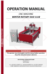
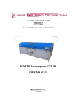
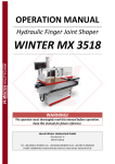
WINTER Single-side Glue Spreader MAXI Single/ Double-side Glue Spreader MAXI Twin
㎜
WINTER Single-side Glue Spreader Maxi Single
WINTER Double-side Glue Spreader Maxi Twin
User Manual
㎜㎜㎜㎜㎜㎜㎜㎜㎜㎜㎜㎜㎜㎜㎜㎜㎜㎜
㎜
Read this User Manual carefully before use
Keep it in a proper way for future reference
Henrik Winter Holztechnik GmbH
Druckereistr. 8
04159 Leipzig
Tel. +49 (0)341/4619021
Fax. +49 (0)341/4618358
Funk: +49 (0)171/2820443
Email: [email protected]
Internet: www.henrik-winter.de
WINTER Single-side Glue Spreader MAXI Single/ Double-side Glue Spreader MAXI Twin
Contents
1
Safety Instructions ------------------------------------------------------------------------------------------------2
1.1 Instructions-----------------------------------------------------------------------------------------------------------2
1.2 Responsibilities -----------------------------------------------------------------------------------------------------2
1.3 Safety Devices & Precautions-------------------------------------------------------------------------------------2
1.4 Safety Warnings & Labeling---------------------------------------------------------------------------------------3
1.5 Nameplate-------------------------------------------------------------------------------------------------------------4
2
Specification--------------------------------------------------------------------------------------------------------5
2.1 Purpose and Applications-------------------------------------------------------------------------------------------5
2.2 Main Technical Parameters-----------------------------------------------------------------------------------------5
2.3 Structure of Machine------------------------------------------------------------------------------------------------6
2.4 Overall Dimension --------------------------------------------------------------------------------------------------7
3 Operating Environment, Lifting and Installation ---------------------------------------------------------------7
3.1 Operating Environment---------------------------------------------------------------------------------------------7
3.2 Lifting ----------------------------------------------------------------------------------------------------------------8
3.3 Installation -----------------------------------------------------------------------------------------------------------8
3.4 Storage----------------------------------------------------------------------------------------------------------------9
4
Operation of Machine---------------------------------------------------------------------------------------------9
4.1 Operating Position--------------------------------------------------------------------------------------------------9
4.2 Parts Description---------------------------------------------------------------------------------------------------10
4.3 Installation & Adjustment ----------------------------------------------------------------------------------------12
4.4 Operation of Machine---------------------------------------------------------------------------------------------13
5
Maintenance of Machine-----------------------------------------------------------------------------------------13
6
Electric Safety-----------------------------------------------------------------------------------------------------14
6.1 Safety Guidelines for Electric System ------------------------------------------------------------------------14
6.2 Electric Schematic Diagram-------------------------------------------------------------------------------------17
7
Common Failures & Shooting Methods-----------------------------------------------------------------------19
8
Fragile Parts------------------------------------------------------------------------------------------------------19
9 Packing List-------------------------------------------------------------------------------------------------------20
10 Factory Address---------------------------------------------------------------------------------------------------21
1
WINTER Single-side Glue Spreader MAXI Single/ Double-side Glue Spreader MAXI Twin
1 Safety Instructions
1.1 Instructions
All people related to the use of this tooling machine should have a careful reading of this User
Manual so as to learn the operation procedures, safe operation knowledge and maintenance of
this machine specified in this Manual. You should also place this Manual near to this machine for
your convenience.
The copyright of this User Manual is reserved by Weideli, and this Manual is only provided for
use by the purchaser and its employees. All content specified in this Manual shall not be copied,
duplicated, handed out or transferred in any way. Otherwise, we will claim against such person as
breaks these principles.
1.2 Responsibilities
The regulations and conditions in relation to the use of this tooling machine is strictly binding, and
we shall not be responsible for any personal injury or loss of properties caused by one or more of
the following reasons:
. Failure to observe the regulations and provisions specified in this Manual for transportation,
installation, commissioning, operation, warning and maintenance of this machine;
. Operation of a tooling machine with any safety hazard or faulty device;
. Improper installation or forcible removal of safety protection devices;
. Processing of workpiece exceeds the designed capacity of this machine or the cutters and
spare parts used are out of the designed range of this machine.
. No reliable earthing device installed for this machine;
. Unauthorized change over the structure and control of this machine, such as the change of
specification, running speed and control method.
. Forcible disassembly or replacement of spare parts without obtaining the knowledge about
the structure and control method of this machine;
. Safety precautions not well conducted when checking, maintaining and repairing this
machine;
. Insufficient monitoring over the wearing of parts and disasters brought by Act of God.
1
3 Safety Devices & Precautions
1 All safety devices must be installed properly before use of this machine in order to ensure
a safe operation;
2 Disassembly of the safety devices is only allowed when the power supply of the this
machine is turned off;
3 Operators should fully understand all safety guidelines and danger warnings specified in
the markings;
4 Please operate this machine only when all safety devices are under normal working
conditions;
5 Make sure that nobody will be injured because of the starting of this machine before
startup.
6 Sufficient attention should be drawn to any minor error or failure, and regular check and
inspection should be conducted at least once for this machine.
2
WINTER Single-side Glue Spreader MAXI Single/ Double-side Glue Spreader MAXI Twin
7
Transportation, installation, commissioning and maintenance of this machine should be
only done by the professional staffs.
8 Installation and checking for electric system of this tooling machine shall be conducted by
those electric technicians who have related knowledge and experience and the
background in mechanical driving field.
9 Check the electric equipment regularly and handle all loose or damaged electric parts in
time. No checking or maintenance is allowed to be done when the machine is live.
When checking or maintenance, the main switch shall be shut down and leave a man to
watch over it.
1.4
Safety Warnings & Labeling
㎜
㎜㎜㎜㎜㎜㎜㎜㎜㎜㎜㎜㎜㎜㎜㎜㎜㎜㎜㎜㎜㎜㎜㎜㎜㎜㎜㎜㎜㎜㎜㎜㎜㎜㎜㎜㎜㎜㎜㎜㎜㎜㎜
㎜
Warning
in this label requires the operator to strictly
㎜ the specifications. Any carelessness may
observe
lead to body injury.
㎜
㎜
㎜
㎜
㎜
The label indicates the correct power with
㎜㎜㎜㎜㎜㎜㎜㎜㎜㎜㎜㎜㎜㎜㎜㎜㎜
applicable voltage, current and
㎜ frequency. Any
carelessness may lead to a damaged machine or
㎜
fire.
㎜
㎜
㎜
㎜
㎜
㎜
This mark indicates that the running direction of the
main shaft must be correct, otherwise it may lead to
body injury.
㎜
㎜
㎜
㎜㎜㎜㎜㎜㎜㎜㎜㎜㎜㎜㎜㎜㎜㎜㎜㎜㎜㎜㎜㎜㎜㎜
㎜㎜㎜㎜㎜㎜㎜㎜㎜㎜㎜㎜㎜㎜㎜㎜㎜㎜㎜㎜㎜㎜㎜㎜㎜㎜㎜㎜㎜㎜㎜㎜㎜㎜㎜㎜㎜㎜㎜㎜㎜ This label tells you not to touch this part when
power on, otherwise it may lead to electric
shock
This label is for earthing direction indicating that
this machine must be grounded and preserved the
earthing line here. Avoidance of this step may
lead to electric shock or that the machine is burnt
down.
This label is used to warn you not to open the
protective cover when the machine is running;
otherwise it may lead to your hand injury.
3
WINTER Single-side Glue Spreader MAXI Single/ Double-side Glue Spreader MAXI Twin
㎜
1.5 Nameplate
Check the model number, serial number and production date to confirm whether they
are in compliance with the purchase contract and check whether the machine is damaged or
not or whether any part is lost or not.
(1) Model Number
MH 6
1
06 B
Improvement Serial No.
Maxium Working Width: 600mm
Single-side Glue Spreader
2 is double-side
Glue Spreader Code
(2) Nameplate of Glue Spreader, See Figure 1-1
Figure1-1 Nameplate
2 Specification
2.1 Applicable Range and Features
This machine is mainly used for spreading UR glue, PERNOL-RESORCIONOL glue and
PVAC glue and EPI glue by rolling, applicable to the pre-gluing of plywood.
This machine is made with detachable AL-alloy framework allowing it beautiful in design and
convenient
Each roller is driven by a motor separately providing more reasonable power.
Roller positions are preserved for users to install backup rollers, enabling it to be a
double-side glue spreader.
Copper glue stopper is adopted to prevent the glue from leaking
★ Synchro-lifting mechanism is used to satisfy the requirements for processing different
thickness of boards.
★ Wheels installed under the seat to make the machine movable freely.
4
WINTER Single-side Glue Spreader MAXI Single/ Double-side Glue Spreader MAXI Twin
2.2 Main Technical Parameters
model
MH6106B
Max. Working Width
Max. Thickness
Workpiece
of
MH6206B
600
600
100
100
Feeding Speed
22m/min
22m/min
Power
0.37kw×3
0.37kw×4
Overall Dimension
Weight
1100×810×1650
1100×860×1650
450
450
5
WINTER Single-side Glue Spreader MAXI Single/ Double-side Glue Spreader MAXI Twin
2.3 Structure of Machine
Al-alloy Frame
Stainless Steel Feeding
Roller
Synchro-lifting Mechanism
Motor
Glue Spreading Roller
Glue Basin
Control Cabinet
Seat
Main Power Switch
`
㎜
㎜
6
WINTER Single-side Glue Spreader MAXI Single/ Double-side Glue Spreader MAXI Twin
2.4 Overall Dimension See Figure 2-1(MH6106B)
1650
㎜
``㎜㎜㎜㎜㎜㎜㎜㎜㎜㎜㎜㎜㎜㎜㎜㎜㎜㎜㎜㎜㎜㎜㎜㎜㎜㎜㎜
1100
㎜㎜㎜㎜㎜㎜㎜㎜㎜㎜㎜㎜㎜
810
㎜
Figure 2-1 Overall Dimension
3 Operating Environment, Lifting, Installation and Storage
3.1 Operating Environment, See Figure 3—1
Figure 3—1
Operating Environment
Ambient Temperature
0--45°
Ambient Humidity
Less than 90%RH
Environment
No corrosive or inflammable gas or oil mist indoor
7
WINTER Single-side Glue Spreader MAXI Single/ Double-side Glue Spreader MAXI Twin
Less than 1000m
Elevation
3.2 Lifting
This machine can be shipped partially or wholly. Generally, it is shipped wholly. During the
transportation, please take necessary measures to protect the machine from sunshine and
rainfall. When unloading, professional workers are required to unload this machine.
(1) During loading and unloading, effective safety protection devices should be in place and no
people is
allowed to stay around the site except related workers.
(2) Use the capable crane or fork lift and make sure that the machine can remain stable during
the process.
(3) After unloading, remove all tools and safety devices in time.
3.3 Installation
3.3.1 Placement of Machine
This tooling machine needs to be placed on the hard cement ground which should be flat and
smooth enough. Sufficient space should be preserved around the machine. Level calibration
should be done vertically and horizontally for this machine. The calibrated value shall not be
more than 0.5
.
3.3.2 Requirements for Power Supply
The required power supply is: 3-phase AC power, voltage: 380V 400V and frequency: 50Hz.
3.3.3 External Power Connection
(1) Power Distribution
According to the requirements for power supply specified in the switchgear cabinet, Connect the
power supply with same voltage, current and frequency at Position C on the incoming wire box.
(2) Running Direction of Motor
The right running direction of motor is: left motor runs counterclockwise and the right motor runs
clockwise (see from top to bottom).
3.3.4 Wiring
(1) Before wiring, first make sure that the power supply required for the machine is same with the
power supply provided by your factory.
(2) the external power lines should go through the automatic load switch before connecting with
this tooling machine, and then connect the power lines with L1, L3, L3 and PE.
(3) This machine should be properly grounded.
8
WINTER Single-side Glue Spreader MAXI Single/ Double-side Glue Spreader MAXI Twin
3.4 Storage:
In order to prolong the service life the tooling machine, please avoid the following:
Long-time Direct Sunshine
Stored at a humid place
Violent Vibration
Unauthorized Approaching
4. Operation of Machine
4.1Operating Position Fig 4-1
2000
㎜
㎜
Other Articles
Stainless Steel Glue
Level
Adjusting
Roller
㎜
Motor
㎜
Glue Roller
㎜
㎜
Control Cabinet
㎜
㎜
800
800
㎜
㎜
㎜
Operator
㎜
Other Articles
㎜㎜㎜㎜㎜㎜㎜㎜㎜㎜㎜㎜㎜㎜㎜㎜㎜㎜㎜㎜㎜㎜㎜㎜㎜
2000
㎜㎜㎜㎜㎜㎜㎜㎜㎜㎜㎜㎜㎜㎜
㎜
㎜
㎜
Fig 4-1 Operating Position Figure
9
WINTER Single-side Glue Spreader MAXI Single/ Double-side Glue Spreader MAXI Twin
4.2 Parts Description
1
Buttons on Control Cabinet
Main Power Switch: before use, this switch should be turned on to “1” indicating the power is on,
and when turned to “0”, it indicates the power is shut down.
Emergency Stop Button: In the event that any accident or failure occurs when the machine is
running, press down this button and the machine will stop immediately
Before starting, this button must be at “Reset” position.
Glue Roller Start Button: Once the main power switch is turn on, press down this button to start
the glue roller.
Glue Roller Start Button: Once the main power switch is turn on, press down this button and the
glue roller will stop working.
Glue Spreading Roller Start Button: Once the main power switch is turn on, press down this
button, and the glue spreading roller will start working.
Glue Spreading Roller Start Button: Once the main power switch is turn on, press down this
button, and the glue spreading roller will stop working.
㎜
Glue Roller Stop Button
Glue Roller Start Button
Glue㎜Spreading㎜㎜
Roller㎜Stop㎜Button
E-stop Button
Main Power Switch
Glue㎜Spreading㎜Roller㎜Stop㎜Button
㎜
㎜
㎜
㎜
㎜
10
WINTER Single-side Glue Spreader MAXI Single/ Double-side Glue Spreader MAXI Twin
2 Electric Control Cabinet
㎜
breaker
Main Power Switch
Transformer
fuse
Thermal relay
AC contactor
㎜
(3) Glue Level Adjusting Device
By adjusting the hand wheel show as the Figure above, precision and even spreading effect will
be obtained. This device is used to adjust the distance between glue spreading rollers. When
spreading glue, the spreading rollers should keep touch with the mixer.
Note: The glue spreading roller can’t be adjusted to be too close to the glue level adjusting roller;
otherwise the heat produced by friction may lead to temperature increase of the spreading roller
or make the motor damaged because of overload.
11
WINTER Single-side Glue Spreader MAXI Single/ Double-side Glue Spreader MAXI Twin
(4) Synchro-lifting Adjusting Device
By adjusting the handle shown in the left picture, you can
adjust the distance between the upper glue roller and the
lower roller. When processing workpieces with different
thickness, you can get the precision distance by adjusting
this handle.
4.3 Installation and Commissioning
1
Installation
Place this machine on the flat and hard ground and use a gradienter to adjust the level of
machine, and then connect the machine housing with the earthing, and finally connect with the
power same with the power required for this machine with applicable voltage, current and
frequency.
2 Running Direction of Glue Roller
Glue Spreading Roller
First start the machine to observe whether the running direction
is correct. The right direction is shown as the figure.
If the direction is wrong, exchange the position of any two power
lines of L1, l2 and L3.
3 Adjustment of Workpiece Thickness
There is a gauge opposite to the left side of the machine. When the
pointer is at “0” position, the upper glue roller is just attached with the
lower glue roller. You can make adjustment at that time according to the
thickness of the machine. If the thickness is “10mm” turn the pointer
clockwise to “9mm”. (Note: In order to protect the glue roller from being
worn out, the distance between two rollers can’t less than the thickness
of the workpiece too much, generally 0.5-1.5mm is better. When
spreading glue, the workpiece should be applied at full length, otherwise
the roller will not work evenly which may result in the glue roller worn out
12
Glue Level Adjusting Roller
WINTER Single-side Glue Spreader MAXI Single/ Double-side Glue Spreader MAXI Twin
and uneven spreading.
4
Glue Filling
Before fill the glue into the glue roller, please
first adjust the glue level wheel to allow a suitable
distance between the glue roller and the upper
rolling stick, and then fill glue at the place where the
black arrow points (Right Figure). (Note: before filling
glue, it is not allowed to start the machine when the
glue roller is tightly close with the rolling stick,
otherwise it will damage the surface of the glue roller).
5 Adjustment of Glue Level
By adjusting the left and right adjusting hand wheel to
adjust the thickness and evenness of glue. The two wheels can’t
be interactive. You need to adjust them respectively. You can
stop adjusting until the glue becomes even.
4.4 Operation of Machine
1
Before starting, make sure that nobody is touching the rollers or any other moving parts.
2
Check each part is at right place and all safety devices are well fastened.
3
Turn the main power switch to “O” position and press down the two green start buttons;
4
Adjust the distance between the glue roller and the upper rolling stick until they get close
with each other enough;
5
Fill the glue. When filling, be careful for your safety. Your body can’t touch the glue rollers.
6
After the glue is filled, adjust the synchro-lifting handle and glue level adjusting wheel
according to the thickness of the workpiece so as to apply the glue evenly on the
workpiece.
7
Press down the red stop button to stop the machine and turn the main power switch to”1”
position.
Note: complete cleaning should be done before the machine is shut down
13
WINTER Single-side Glue Spreader MAXI Single/ Double-side Glue Spreader MAXI Twin
5
Maintenance
5.1Daily Maintenance:
1 Keep the machine clean, and all driving parts and contacts should be well lubricated.
2 Do not place any other things on the machine;
3 As the glue will become hard which may seriously damage the glue roller, you must clean off
the glue in the glue basin, glue rollers and the glue level adjusting roller using water if the
machine stops for over 15 minutes.
5.2 Cleaning:
1
In order to keep the machine in good conditions, it is necessary to clean the machine.
2 When cleaning, it is possible to hurt people, so pay attention to the safety.
3 Please try to use up all glue in the machine. When cleaning, please add 30
water to mix
with the glue, and then open the clearance between the glue roller and other rollers to clean
off the glue.
4 Narrow the clearance between the glue roller and the two rolling sticks to the normal
position , and then add warm water with the maximum temperature of 30
and mix with the
remaining glue. Open the clearance between the glue roller and the glue level adjusting
roller to discharge the water.
5 Shut down the machine and turn the main power switch to “ON” position.
6 Take down the two copper glue stoppers on both sides and clean them and the bearing with
the warm water.
7
If the surface and groove of the glue roller need to be cleaned, first take down the glue roller,
and clean it using long-handle brush and warm water (Note: do not use any sharp or hard
tools, dirty cloth or cotton waste for cleaning. Before assembly, clean the shaft and bearing
first.).
5.3 In-process Maintenance:
1
Operate this machine with the correct method. It is not allowed that the pressing is our of
the designed capacity of this machine.
2
No maintenance is allowed to be conducted when working. When the machine is running,
the operator should not leave away until the machine is shut down as required.
3
Before repairing and replacing the spare parts or assembly and reassembly of motor, the
power should be shut down.
14
WINTER Single-side Glue Spreader MAXI Single/ Double-side Glue Spreader MAXI Twin
5.4 Periodic Maintenance:
1
Before each processing, first check the driving parts and safety devices are properly
installed, and run this machine without putting on the workpieces to check whether its
action is correct, flexible and reliable.
2
Overall check should be made once per month focusing on the elements in the switchgear
cabinet, overtravel limit stop and pull-string emergency stop as well as whether the driving
parts are well lubricated and whether the safety protection devices are well fixed. If
necessary, adjust or replace such devices.
5.5. Storage Maintenance
1
If you do not use this machine, please clean it and apply lubricating oil to all driving parts
and pack it properly.
2
This machine should be stored at a dry and well-ventilated room to avoid the direct
sunshine and rainfall.
3
Selection of Lubricant for Electric Sliding Track: Calcium-based Lubricant.
or Caltex Meropa68 Lubricant
Caltex Multifak Ep2 Lubricant
6 Electric Safety
6.1 Safety Guidelines for Electric System
1
Only well-trained professional persons with professional knowledge are allowed to conduct
the electric repairing or remove troubles.
2 Do not modify or ignore the protection devices;
3 Before starting, have a careful reading of the User Manual and warnings.
4 When the failure is confirmed, do remember to shut down the power and the main switch
should be locked.
5 Be aware of the humid area to prevent the electric shock
6 Before the electric power is distributed to any equipment, any person should be clean and
7
Do not open the switchgear cabinet except that it is necessary to check the electric
equipment.
8 Do not change the circuit unless authorized by the qualified manufacturer
9 When replacing the electric parts, first confirm the new parts are in compliance with the
specification, including the color code on the power cable.
10 When operating the electric equipment, do not wear any metal glasses, necklace, ring,
watch or bracelet, etc.
15
PE
QS1
T1
S1
QF
(M电6206B)
16
U1
W2
0.37KW
V2
T6
T5
0.37KW
U2
S6
S5
4A
M2
3~
W1
FU5
4A
FU6
M1
3~
V1
1A
R6
KM2
R5
FR2
T4
T3
4A
FR1
S4
S3
FU3
4A
FU4
1A
R4
KM1
R3
4A
4A
T2
S2
R2
FU1
FU7
U3
1A
FR3
R7
KM3
R6
4A
FU8
12
W3
T7
T6
4A
FU9
0.37KW
M3
3~
V3
S7
S6
4A
1.5mm2
FU11 1A
3料0V
/63VA
FU10 1A
2
1 TC
4
0VAC
5
SA2
9
SA1
料
FR3
7
FR2
控
FR1
FU12 1A
110VAC
3
HL1
11
KM1
HL2
12
KM2
HL3
KM1
KM1
14
SB1
13
SA3
KM2
KM3
1控
SB2
15
SA4
HL4
KM2
6.2
FU2
R1
WINTER Single-side Glue Spreader MAXI Single/ Double-side Glue Spreader MAXI Twin
Electric Schematic Diagram
MH6106B
1.
5m
m2
17
F
E
D
C
B
A
节
V
S
W
T
1
㎜0.37KW
M2
V2
W2
㎜0.37KW
2
节2
节1
M1
2FR
1FR
2KM
1KM
W1
2
4F节 5F节 6F节
1.5mm2
3x4A
V1
1F节 2F节 3F节
1.5mm2
QF
R
3x4A
QL
3料0VAC
L1 L2 L3 PE
1.5mm2
1
节3
3FR
3KM
3x4A
W3
3
㎜0.37KW
M3
V3
7F节 料F节 9F节
1.5mm2
3
2
3料0VAC
1
TC
节4
4FR
4KM
3x4A
W4
4
㎜0.37KW
M4
V4
10F节 11F节 12F节
1.5mm2
14F节
1A
13F节
1A
4
4
110VAC
3
15F节
2A
5
5
7
6
4FR
17
3FR
9
2FR
料
1FR
2SA
1SA
5
6
10
6
(1SB)
㎜1电L
11
1KM
(3SB)
㎜3电L
12
3KM
7
1KM
7
2KM
2SB
13
1SB
14
1KM
(2SB)
㎜2电L
3KM
4SB
15
3SB
16
料
4KM
3KM
料
(4SB)
㎜4电L
F
E
D
C
B
A
WINTER Single-side Glue Spreader MAXI Single/ Double-side Glue Spreader MAXI Twin
WINTER Single-side Glue Spreader MAXI Single/ Double-side Glue Spreader MAXI Twin
7. Failures and Troubleshooting Methods
If the following failures are found when checking, you may refer to the troubleshooting methods
given below for preliminary treatment. If failure still exists after doing so, please consult with the
manufacturer for technical support.
㎜
Failure
Reasons
Killing Methods
Open phase of power or short circuit
Check and correct
When power on, the
Damaged control AC contactor or
Check the AC contactor and
motor unable to start
the thermal relay in open circuit
thermal relay
Fuse burnt
Check and replace t he fuse
The left and right adjusting wheels
Adjust
are not well adjusted
consistence
Glue roller damaged
Replace the glue roller
Uneven spreading
both in the left and
right sides of the
workpiece
No matter how to
adjust, the glue can
not spread evenly
the
two
wheels
㎜
㎜
8 Fragile Parts
S/N
Name
Quantity
1
Glue Spreading Roller
1
2
Glue Level Adjusting Roller
1
3
Glue Stopper
1
4
Bearing
2
9. Packing List
Packing List
Weideli Woodworking Machinery Industrial Co., Ltd.
S/N
1
2
3
4
Checker:
Name & Specification
Main Machine
User Manual
Certificate of Compliance
Warranty Card
Date:
18
Model No.
MH6106B
Quantity
Remarks
1
1
1
1
in