1
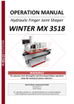
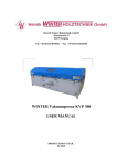
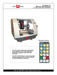
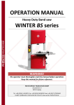
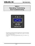
OPERATION MANUAL CNC MACHINE WINTER ROTARY DUO 1118 WARNING! The operator must thoroughly read this manual before operation. Keep this manual for future reference. Henrik Winter Holztechnik GmbH Druckereistr. 8 04159 Leipzig Tel: +49 (0)341/ 4619021 Fax: +49 (0)341/4618358 Funk: +49 (0)171/2820443 Em@il: [email protected] Internet: www.winter-holztechnik.de Preface The users’ manual introduce in detail installation, attention items and maintenance, common malfunction analysis, simple engraving skills. CNC machine belongs to high-precision numerical control equipment. If improperly installed, will affect the machine precision, stability and life. Before installation, please read Users Manual in detail. Machine Specification WINTER ROTARY DUO 1118 : Performance Parameters X Y Z Travel Size 1100-1800-700 Max Running Speed 6000 Max Engraving Speed 3000 Repeated accuracy of 0.02 positioning Connecting terminal USB Engraving instruction G Code Spindle Power 1.5KW Spindle Speed 24000 Working Voltage 220V 2 Tool diameter Software System 3.175 6 Running XP Caution 1. CNC machine is strictly prohibited to use the power supply that fall short of rated voltage. 2. Make sure to operate the machine in accordance with the Manual,working size may not exceed the machine actual size. 3. No super-strength, overload job! 4. As to the machines with screw guide of the working table size over 1200*2400mm, gantry should be located in the middle of the machine so that to lest screw guide should drop to effect on the concentricity and accuracy after finishing your work. 5. Please do not operate machine when smoke, making some noise and other anomalies. 6. It is strictly prohibited to operate wearing gloves. 7. Do not clean machine parts and the keyboard using the corrosive fluid 8. Please choose the right tools and proper feed rates according to different materials and end depth. 9. Make sure the spindle rotate first before finished the installing the tool for Z-axis positioning and the file output. 10.Do not change or destroy the original power cable. Power cable can not be so excessively bended, strong pulled, tied up and under heavy pressure. 11.Do not touch the tool by hand in the processing of working 12.Machine can not be infiltrated with liquid, such as metal objects. Please clean the machine in time when finish your job, add lubricants to the screw guide, rail orbit gear rack regularly. 13.The bucket that is with water pump should be covered with a bucket cover to prevent debris and dust falling into the water to block water pipe and the spindle. 14.Make sure the water pipe that connect the spindle fixed firmly, water sources clean, water flow normally when the water-cooled spindle working. If not, the motor will be damaged by electrical leakage or water break. Water pipes should be replaced if it ageing. Coolant fluid can 3 adopt the emulsified oil and 10 # machine oil. 15.The spindle motor should be rotated firstly before the machine running. Check if the rotation direction is reversed. If rotating in the wrong direction, shut off the power to change the direction of any two wires of three wires which marked UVW in inverter, the motor must not rollback. 16. Replace the cooling liquid timely if the temperature in water bucket exceeds 40 degrees. Pay attention to the water bucket freezing in winter. 17. Do not put any object on table surface except the job you want to process. 18.Make sure the rotating speed of the spindle reach to rated speed in process of working. 19.Grounding: make sure connect the ground to the wires that connected the back of the machine. 20.Do not connect or disconnect the connector joints and plugs with power on 21.The longest continuous working time of the cnc router are 24 hours, if it runs a long time, it will affect the electrical system and the life of some spare parts, thus will affect the accuracy of machine. 22.Make sure turn off the power before open the door of the control cabinet, only the professional maintenance is permitted to repair. 23.When the supply voltage exceeding the rated voltage + -10%, one transformer is proposed to use. 24.The machine should be far away the outside vibration source to avoid the strong electromagnetic fields nearby. 25.Do not touch the stepper motor in case of scalding. 26.Please clean the dust in collets regularly to avoid loosening tools. 27.DSP control handles can not be pressed by heavy objects or hit .Clean the virus regularly in case the files are infected, if not, the machine will not work properly. 28.Do not hit the sensors. It is prohibited to touch the sensors with metal, or else the machine will not work normally 4 Machine installation 1. Environment: Surrounding humidity: 0-40degrees, in the process of stopping running: make sure the temperature is above zero (the liquid within the watercooled spindle should be released if the temperature is below 0 degree) Humidity: Maximum 75% non-condensing (relative humidity) Short-term: 95% (one month) 2. After received the machine, open packaging, move machine from wood box, and placed it in the level position. In the process of placing, do not to bump the machine. 3. When placing finished, open tool box and take wires to connect power. If it is air plugs you get, please connect it by the number marked on them to check if the circuit is normal. 4. Open computers to install the corresponding driver and application software. (See user manual or CD with introduction) 5. After finished installation, set the internal parameter. Open machine to check if the machine running direction is correct, then reset accurately. 5 System Parameter (1)NCSTUDIO INTERFACE Title Bar Menu Bar Tool Bar The NC state window The state bar Multi-function fold window Auto/Manual/Calib…fold window NCSTUDIO System→Company parameter →Password:NCSTUDIO →Motor Parameter: Ball Screw Machine:X 0.003125 Y0.003125 Z0.003125 X0.00625 Y0.00625 Z0.003125 Gear rack machine:. X0.0147 Y0.0147 Z0.003125 Z axis maximum speed of 10000 changed to 1000 6 The end of mechanical coordinates: X direction Y direction changed to the actual size of the machine Z axis maximum turning speed of 1000 could be converted to 600 DSP control panel Button Function Positive movement of Z axis, Menu upward , figure 1 inputting Positive movement of Y axis, accelerate process speed, figure 2 inputting, different property selecting in Menu Positive movement of Z axis, figure 3 inputting, rise spindle speed in process Working origin of X axis and Y axis setting, figure 4 inputting Negative movement of X axis; Menu downward, figure 5 inputting Negative movement of Y axis; slowdown process speed; figure 6 inputting different property selecting in Menu Negative movement of Z axis, figure 7 inputting, spindle speed adjusting in process Z axis origin setting ; figure 8 inputting Axes home to machine tool origin, figure 9 inputting Manual moving mode, high speed or low speed selection, figure 0 inputting Spindle startup/stop, decimal point inputting 7 Menu setting entering, negative symbol inputting, multi process state checking, All axes go working /inputting/operating origin: confirm of motions Manual move, continue, step and distance modes selection Cut process running/pause/inputted words delete High/low speed parameter adjust, Cut stop/selections, inputting and operating cancel process DSP Control Panel→System Setup→Impulse Equivalent: Guide Screw Machine: X 320 Y 320 Z 320 X160 Y160 Z320 Gear rack machine: X68 Y68 Z320 Machine Dimensions: X-axis Y-axis machines replaced by the actual size Spindle Setting: Spindle State: 8 Input Volt: 0 1 2 ↑ ↑ ↑ 0 1 2 3 0 ↓ ↓ ↓ ↓ 1 ↑ ↓ ↓ ↓ 2 ↓ ↑ ↓ ↓ 3 ↑ ↑ ↓ ↓ 4 ↓ ↓ ↑ ↓ 5 ↑ ↓ ↑ ↓ 6 ↓ ↑ ↑ ↓ 7 ↑ ↑ ↑ ↓ 8 The calculation of pulse equivalent of Rotary PCI Card controling machine: 3.14 diameter 15 1600 Diameter (diameter of the material) DSP control machine: 1600 3.14 diameter 15 The Setting and The Use Of The Menu Press “menu” button to enter into the menu item under the main page. Press “X+”and“X-”, move the cursor to choose different menu item, and then enter by pressing “confirm” button. 1. The MACHINE SETUP is a configuration which is used to adjust the controller to the mechanism of the machine body. It includes: impulse equivalent weight, the setup of the machine \body size, go home setup, the setup of the main axis, the definition of the level, the definition of the impulse, the thickness of the auto-feeding machine ,the clearance of the ball screw and so on. We suggest that the parameter should be set up by the producer; there is no need to change the parameter once it has been set up by the producer. Press the corresponding data button to change the parameter, press “cancel” button to move the cursor. Press “Y+”and“Y-” to change the attribute. Press “cancel” button to back to the higher up menu until exit. 2. AUTO PRO SETUP sets the linear accl, the curve accl and the G code to read the attribute. You can press the corresponding data button to input the data, and press “confirm” button to save the changes. Press “Y+”and “Y-” to change the attribute, press “confirm” button to save the changes. Press “cancel” button cancel the changes and return to the higher up menu. 3. SYSTEM SETUP sets the language of the system, the data area in the format auto-check function and the system upgrade. Press “X+”and “X-”to move the cursor to choose and then press “confirm” button to confirm the changes. 9 4. ADVANCED PRO SETUP sets some files which need special process. Such as "Row Column" can set the number of the row, the list and the distance between the row and the list. The configuration of mill level, protecting the file and other configuration of the special requirements .Press “X+”and “X-”to move the cursor to choose. Press “confirm” button to enter into the submenu item. Press “confirm” button to save after inputting the right data, Press “cancel” button to cancel the changes and return to the higher up menu. 5. Press “confirm” button to see the emergency /common program of the system. 6: Advanced process Press “ ”+“ ” button,, to enter into the advanced process menu after setting the advanced configuration. Then press “X+”and “X-”to move the cursor to choose, press “confirm” button to enter, operate according to the instruction step by step. 7: UPDATE If the system need to be upgraded, the users can get the corresponding upgrade edition to the USB disk from us, and then connect the control card with USB disk, then enter into the SYSTEM SETUP, move the cursor to the SYSTEM UPGRADE automatically, press “confirm” button to choose USB file list, find the upgrade file after entering and then press “confirm” button, the system will upgrade automatically. The system will instruct after upgrading, press “confirm’ button to exit, then the upgrading has been finished. 10 Machine Operation 1. Connect the Control Panel to the machine by the 50 pin cables and get the power supply through. 2. The LCD will show “whether go home or not?”, press “confirm” button and go home of the machine body ,and then press “Delete” button not to go home, press “cancel” button only Z-axis goes home. 3. Move X,Y,Z these three axis to the pointed place that the bit will start and press “XY→0”and “Z→0” to affirm the working origin. 4. Press “RUN” button, it appears “file chosen” item, move the cursor to choose the type of the file. Press “confirm” button to enter the USB disk file list or inner file list. As to the USB disk file list, press “X+” and“X-” move the cursor to the pointed file, and then press “confirm” button again to start working. As to the file in the inner file list, press the corresponded number button to choose the file you need to process, and press “MENU’ button to find the file by paging up and paging down. 5.It will appear processing parameter configured item after choosing the process file, choose different parameters by pressing “X+” and “X-” to move the cursor., and then download data setting by pressing “confirm” button. Press “DELETE” button to DELETE the wrong input, Press “confirm” button to confirm the data after finishing inputting, press “cancel” button to back to the original data when amending the data. The users should integrate the actual information about the machine body and the processing requirements to amend the above parameter, or it will result in process mistakes. 6.Press “cancel” button to exit the amend of process parameter after finishing setting the process parameter..The system begins to check the process code, press: confirm” button to start process after checking. 7.Press “Y+”“Y-” to change the speed rate during processing , press “ +Z+”and“ +Z-” to change the rotary speed of the spindle. 8. Press “pause” button to adjust the position of the three axes during processing, press “pause” button again it will instruct “the original position”. 11 Press “pause” button to confirm the new position and it begins to process, and then it will continue the processing according to the position where it had not been changed. 9.Press “stop” button to stop process during process, It will instruct “save break point”, if you need to process again at the present position, press “1”or“2”, “3”,“4” “5” or“6”button and press “confirm” button ,then the present process will be saved, if you do not need to continue processing, then press “stop” button again. It will “whether go home?’ press “confirm” button to go home, press “stop” button not to go home. 10.Process on break point: if you need to continue to process the file you have saved which had not been processed, press “RUN” button +the corresponded data button, it will appear the process parameter setting , and the steps are the same as the above 5,6. Press “cancel” botton,the row number of the file on break point will appear, press “confirm” button ,it will begin to check the code, it will start process at the position where it stopped after checking. 11. Process when power off: The control system will save the un-processed data automatically if it going to power off during processing. When it power on again, press “confirm” button first to go home, The screen will instruct “whether to recover from power off” , press “confirm” button, it will execute the process which has not been finished before power off, press “cancel” not to execute the process. 12. After beginning process, the system will show the state of processing .such as the speed ratio, the leaving time of the processing, the speed of processing and the row number of processing file. 12 Maintenance Maintenance is the basic job of machine using; only pay attention to maintenance of machinery, the machine can be ensured durable. ⅠThe maintenance in the preliminary state of machine: There is a running in period as to the new machine; there is a transition and adjustment in this period, make sure check the tightness of joint between the various components after the machine run one week. Mainly check three parts, the joint of the axes coupling (Figure 1), the joint between the backing board and the screw guide (Figure 2),the joints among of the side board ,beam and backing board (Figure 3) The coupling for screw guide Y coupling Z coupling X coupling The joint between screw and backing board The screw fixed place 13 The side of the gantry for screw cnc machine The screw fixed place ⅡThe maintenance of machines using 1. Strictly obey the operating rules and routine maintenance system. 2. Do not open the doors of electrical control cabinet frequently. Do not work with the door opening when machine working. It will cause much dust, wood or metal powder, lest them falling onto the circuit wafer or electronic device in the control cabinet, which will lead to intercomponent insulation resistance drop, or even result in damage to components and circuit boards. 3. Regularly clean the heat output and ventilation system in electrical control cabinet. Check the fans in the control cabinet to see if they work normally. Every quarter, clean the dust in the control cabinet regularly with one dust collector 4. Guides, ball screws, gear racks, sliders, bearings and other transmission components should be washed once a week with kerosene and lubricants added. 5. Vacuum pump maintenance. ﹙1﹚Water cycle vacuum pump The metal mesh of the suction mouth is used to prevent the dust and particles entering the pump body. It should be kept clean at any time to avoid blocking by pump pumping speed decreased, when the pumps do not to use, please power it on every few days for a few minutes lest the pump can not work normally because of rusting 14 ﹙2﹚Air-cooling vacuum pump It should also release the butterfly nut, take out the paper filter core and regularly clean dust filter with high pressure air. Filter ventilation was found not in order or damaged, should be replaced; add oil to the coupling by the high-pressure oil gun according to the time you used. 6. Inverter Maintenance: the inverter has been finished debugging before leaving factory, do not debug and change the wires lest data entry errors by motors or inverter damage. 7. The maintenance when the machine is not to used for a long time: when the machine is not used for a long time, it should be powered on 1-2 times each week, especially in a heaver ambient humidity during the rainy season. It should run about an hour in order to disperse the moisture of the CNC system by using of the electrical heating element itself to ensure the performance of the electronic devices stable and reliable. Troubleshooting I Machine can not go to home, after finished the processing, can not come back to the origin of the working. 1 To see if the sensors are connected, if it is damaged 2. To see if the PCI card is damaged 3 To see if the parameters are right in the control handle 4 To check if the file is correct. 5 After finishing the engraving, Press F7 for PCI card system, press Ok button for DSP system to see if the machine can come back the original. ⅡThe spindle rotational speed less than the specified one. 1 Check if the wires connecting between inverter and circuit board is correct 2. To re-adjust the internal parameters of inverter 15 3. PCI card ,USB cable,circuit board damaged, the parameters in DSP handles setting wrong, set it correctly ⅢEngrave a bad square, bad roundness, serrated jobs, and the machine jitter when it working. 1 Adjust the machine balance, check the slider, motor belts, coupling, to see if it loose and damaged 2 Adjust concentricity and tightness among of the axis bearings block, screw block, motor block,. Ⅳ Malposition 1Check whether the axis lubrication 2. If the speed is too fast, whether the parameters are set correctly 3. Whether there is static or external interference, whether or not there is the Ground wire 4. Check if bearings block, screw block, motor block for x,y,z axis is concentric. 5. Drive current is too small, motor or drives damage. Ⅴ Turn on the machine non- response, without power for machine, the handle non-response, show nothing 1 Change the slot location of the computer and re-install the software. 2 To see if the inner wires within DSP USB cable connect together 3 Check the current by the power supply output in control cabinet, if the wiring in the circuit board are connected correctly, air plug are connected correctly 4 To see if drive, switch, fuse, rectifier damage. Ⅵ Can not distinguish the direction when the machine running 1. USB cable loose 2. PCI card damage. 16 3 Drive wires loose or incorrect wiring 4. The circuit board of PCI Card or DSP control handle damaged. Ⅶ The depth is different when it engraving 1 .To see if the table surface and the engraving materials are flat 2. To see If there is gap among of the axes 3. Strong electric interference, add one filter Ⅸ There is a error with the engraving size. 1 Pulse equivalent (electrical parameters) set incorrectly; modify parameters, clamp the engraving material tightly to prevent the loosening 2 There is a gap between screw block and coupling, adjust it 3 There is a problem in the process of file conversion Ⅹ Vacuum pump stop rotating,no suction and rotate reverse 1. To see if the motor wires and power voltage is normal 2. Water short with in the water pump, stuck or rust with the motor, dismount the rotation axes of the fan motor protective mesh to check 3. Vacuum pump blockage, clean it. 4. Vacuum table surface or pipeline steam leakage, repair it 5. Change the direction of the any two wires of three wires which marked UVW in inverter to change the motor direction. 17