1
Meaning of the symbol :
WARNING ! Read the User Manual before using the fieldmater.
Failure to comply with or apply correctly the instructions of this User Manual preceded by this symbol may result
in bodily injury or damage to the instrument and to the installations.
Thank you for purchasing a Chauvin-Arnoux Fieldmeter and for your confidence.
For best service from this system :
■
read this user manual carefully,
■
observe the precautions for use.
PRECAUTIONS FOR USE
■
■
■
The C.A 42 fieldmeter uses five NiMH 1.2 V/2300 mAh AA model rechargeable batteries, located in an interchangeable
unit in the base of the instrument. Check that the batteries are sufficiently charged for the planned duration of use. The
voltage and remaining charge of the batteries are indicated in the «Options/System Information» menu.
The measuring device remains On and cannot be switched off when the charger is connected.
Conventional batteries (primary cells) are not rechargeable. Never connect the charger if the instrument is operating on
batteries of this type; you could destroy both the cells and the instrument!
WARRANTY
Unless otherwise stated, our warranty is valid for twelve months starting from the date on which the equipment is made available
(extract from our General Terms of Sale, available on request).
28
CONTENTS
1. PRESENTATION..........................................................................................................................................................................................p. 30
2. APPLICATIONS..........................................................................................................................................................................................p. 30
3. DESCRIPTION............................................................................................................................................................................................p. 31
3.1
Front panel.....................................................................................................................................................................................p. 32
3.2
Top.....................................................................................................................................................................................................p. 32
3.3
Bottom..............................................................................................................................................................................................p. 33
4. TECHNICAL CHARACTERISTICS........................................................................................................................................................p. 33
4.1
C.A 42 Fieldmeter.........................................................................................................................................................................p. 33
4.1.1 Oscilloscope function....................................................................................................................................................p. 34
4.1.2 Frequency analysis (FFT)..............................................................................................................................................p. 34
4.2
Probes.............................................................................................................................................................................................p. 35
5. OPERATING PRINCIPLE..........................................................................................................................................................................p. 35
5.1
Measurement of a magnetic field...........................................................................................................................................p. 35
5.2
Measurement of an electric field...........................................................................................................................................p. 36
5.3
Calculation methods....................................................................................................................................................................p. 36
5.4
Oscilloscope option......................................................................................................................................................................p. 37
5.5
Frequency Analysis (FFT) option.............................................................................................................................................p. 37
6. SETTING UP................................................................................................................................................................................................p. 37
7. MEASUREMENT CONFIGURATIONS...................................................................................................................................................p. 38
7.1
Operating modes...........................................................................................................................................................................p. 38
7.1.1 Continuous measurement of an Electric or Magnetic Field - (Measured value)............................................p. 38
7.1.2 Measurement normalized with respect to the reference value of a standard - Weighted Measurement.p. 38
7.1.3 Display of the time variations of a field - Oscilloscope Function.......................................................................p. 39
7.1.4 Display of the variations of a field versus frequency - Frequency analysis (FFT).........................................p. 39
7.2
General configuration of the C.A 42.....................................................................................................................................p. 40
7.3
Selection of a main «Menu».....................................................................................................................................................p. 41
7.4
Selection of an operating mode...............................................................................................................................................p. 42
7.5
Selection of a display mode.....................................................................................................................................................p. 43
7.6
Parameterising of the current configuration......................................................................................................................p. 44
7.7
Optional configurations..............................................................................................................................................................p. 45
7.8
Data transmission........................................................................................................................................................................p. 46
7.9
System information....................................................................................................................................................................p. 46
7.10 On-line help - «?»........................................................................................................................................................................p. 47
8. RS 232 COMMUNICATION......................................................................................................................................................................p. 48
8.1
Connection......................................................................................................................................................................................p. 48
8.2
Configuration..................................................................................................................................................................................p. 48
8.3
Application software - LOG42.................................................................................................................................................p. 48
8.3.1 Installation..........................................................................................................................................................................p. 48
8.3.2 Use.......................................................................................................................................................................................p. 48
8.3.3 Languages..........................................................................................................................................................................p. 48
8.3.4 Configuration for communication..............................................................................................................................p. 48
8.3.5 File import procedure....................................................................................................................................................p. 49
8.3.6 Filtering of imported data..............................................................................................................................................p. 49
8.3.7 Definitions.........................................................................................................................................................................p. 51
8.3.8 HELP menu........................................................................................................................................................................p. 51
9. MAINTENANCE...........................................................................................................................................................................................p. 52
10. TO ORDER...................................................................................................................................................................................................p. 53
29
1. PRESENTATION
When in operation, any system that uses electric power generates electromagnetic radiation that can cause technical problems
in instruments exposed to them (e.g. flicker of video screens); this is true of electrical machines generally - motors, welding sets,
induction furnaces, high-voltage lines, transformer stations, household electrical appliances, etc. - and of electronic instruments,
whether they process or transmit information, are used for monitoring or measurement, etc.
The electromagnetic fields these systems produce may be propagated far beyond their enclosures (housings) or the premises
on which they are installed. Just how far depends on their design.
These electromagnetic fields may so perturb the operation of electrical devices nearby as to make normal use of them impossible.
These systems are then said to be electromagnetically incompatible.
The strengths of the radiated magnetic and electric fields in the vicinity of an electrical or electronic device must accordingly be
measured when a new system is installed nearby.
In addition to the purely technical problems of electromagnetic compatibility between instruments and machines, more and
more consideration must be given to the effects of electromagnetic fields on the human body and even on animals; in particular,
care must be taken to ensure that people living and working near these electrical devices are not exposed to fields liable to
impair their health, permanently or even briefly.
To ensure this, European directives and world standards (IEC, EN, DIN, UTE, VDE, BGV, ICNIRP) have been prepared to
standardize tests in the fields of “Electromagnetic Compatibility” and of “Protection of Individuals” (the standards currently in
use in Europe include VDE0848, prEN50366, BGV B11, ICNIRP, 26BimSchv, etc.).
These standards set maximum acceptable or “reference” levels, which include a safety margin with respect to the known limits.
In practice, the strengths of electric and magnetic fields must be measured to verify the compliance of the installed systems with
these safe limits. These checks require the use of metrological means: this is because, in particular in the case of the electric
field, its propagation is unpredictable and incalculable because of the extent to which it depends on the environment: presence
of metallic structures, relative humidity of the air, nearby plants (vegetation), etc.
The C.A 42 fieldmeter was developed specifically to meet this need to measure low-frequency electric and magnetic fields
(from 0 to 400 kHz, depending on the measuring probe used) and to compare the measured values with the requirements of
the European directives and world standards which are stored in its memory.
The measurements made by the C.A 42, RMS or peak values and their components along three orthonormalized reference
axes, are displayed either as absolute values (V/m or T, multiples and sub-multiples) or in normalized form (percentage of the
reference values prescribed by the stored standards).
These measurements can be made for public- and private-sector applications and for the industrial testing of the conformity of
electrical devices.
In addition to absolute and relative measurements, the C.A 42 has two functions that are very useful for analysing the magnetic
and electric fields measured: an “Oscilloscope” function that displays variations versus time; and a “Frequency Analysis”
function (FFT) that displays the harmonic and non-harmonic components of the signal.
2. APPLICATIONS
Work centres :
Measurement of electromagnetic exposure at the work centre, detection of errors if there are technical problems such as video
screen flicker, compliance with maximum values in the context of work centre safety for persons exposed for occupational
reasons.
Public and private sectors :
Measurement of the field strengths radiated by high voltage lines, transformer stations, etc., and by household electrical
appliances and installations, in the context of checks of compliance with the maximum values stipulated by standards or other,
more stringent, recommendations concerning the exposure to electromagnetic fields of the public and of private users.
30
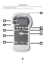
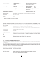
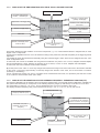
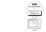
3. DESCRIPTION
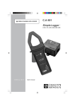
Locations and descriptions of controls
The activation, adjustment, and interconnection devices of the C.A 42 fieldmeter are shown below.
10
1
2
9
8
3
7
4
5
6
31
3.1
FRONT PANEL :
It comprises the control keypad and the display module.
1-
Liquid Crystal Display (LCD) 160 x 140 pixels, backlit, operating in the text and graphic modes. The measurements are
displayed by large digits - 6 x 12 mm.
2-
Drop-down menus that propose various options according to the current measurement configuration.
3-
Cancel key used to exit from the current drop-down menu or configuration function without modifying the previous choice.
4-
Protective elastomer enclosure.
5-
On/Off key:
- A short press on this key switches the measuring equipment on or off.
When switched on, the C.A 42 is in the measurement configuration it was in when last switched off.
- A long press (approximately 5 seconds) switches the backlighting of the display on or off.
Remark: When its internal battery recharges, the instrument is automatically On; it cannot be switched off during recharging.
6-
Main characteristics of the internal isotropic magnetic field measuring probe.
7-
Browser: Direction keys
During a measurement, it is possible to change the parameters of the configuration used, by selecting the menu to be
modified using the “Right” and “Left” direction keys.
The selected menu is identified by a dotted frame around a list of possible choices.
The choice is made using the “Up” and “Down” direction keys.
8-
OK key used to validate the selected configuration parameters.
9-
Function keys
The four yellow function keys are associated with the drop-down menus in the bottom part of the display.
When an up or down arrow or the sign “+” or”-” appears in the box next to one of the function keys, indicating the direction
of change of the value concerned (Measurement range, Time base, Zoom, etc.), a long press (of the order of 4 to 5s) on
this key changes the direction of change.
10 -
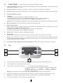
3.2
The internal isotropic magnetic field measurement probe is located at the top of the unit, above the LCD display.
Top :
4
3
5
2
1
1-
Central opening intended to hold the MF 400, MF 400 H and MF05 magnetic field measurement probes.
2-
Coaxial receptacle for connecting the external charger.
3-
Triple-function 12-pole circular receptacle:
1 - Connection of the EF400 electric field probe,
2 - Analogue voltage output by a specialised cord with the following contact
allocations : Vx on 1;
Vy on 2;
Vz on 3;
Gnd on 4.
3 - External Trigger input by specialized cord for Oscilloscope function only TTL levels - on pin 3, Gnd on 4.
Warning: The instrument must be switched off when an external probe is connected or disconnected.
4-
8-pole circular receptacle for connecting the MF 400, MF 400 H, and MF 05 magnetic field measurement probes
Warning: The instrument must be switched off when an external probe is connected or disconnected.
5-
5-pole circular receptacle for RS 232 link with a specialised cord.
32
3.3 BOTTOM :
1
2
3
1-
«Reset» button (see chapter 9 Maintenance page 50).
2-
Internal battery pack. Consists of 5 2300 mAh NiMH AA modules.
3-
Protective cover of the internal battery pack.
The protective cover can be remmoved by pressing simultaneously on its two slotted sides.
For the replacement of the battery pack, see the maintenance chapter.
4. TECHNICAL CHARACTERISTICS
4.1 C.A 42 FIELDMETER:
The C.A 42 fieldmeter has an internal isotropic magnetic field measurement probe (see 10-), and can use one of the following
external isotropic measurement probes (optional):
- MF 05, MF 400 and MF 400 H for the magnetic field,
- EF 400 for the electric field.
The frequency ranges, dynamic ranges, scales, and measurement accuracies depend on the auxiliary probe used.
(see table of characteristics below)
- Display :
Backlit liquid crystal (LCD) display - 160 x 140 pixels.
Measured value displayed by 6 x 12 mm digits.
- Frequency filtering :
Chosen by the user, depends on the standard selected and on the probe used,
With fixed Band-Pass Filters: 16.67 - 50 - 60 - 83.3 - 150 - 180 - 250 - 300 - 400 - 1200
and 2000 Hz
- Stored evaluation standards :
standard (*): ICNIRP Guidelines Occu (Workers) and Gen. Pub (public), EN 50366
BGV B11 Exp.1, Exp.2, Exp.2h/d, - 26. BimSchV - others optional
- Memory :
1MB (corresponding to 15,150 measured values, 80 oscillograms, or 475 frequency
responses)
- Communication :
RS232 serial port Speed from 4,800 to 57,600 bauds, Xon/Xoff, RTS/CTS protocol
- Analog outputs :
3 channels: Vx, Vy and Vz
- Calibrated:
- Frequency range:
- Direct:
33
1V full scale for all ranges used
0 to 30 kHz
Output voltages of the magnetic field
probes only, without modification of
amplitude or frequency band,
- Climatic conditions :
- Operating temperature:
- Relative humidity:
- Altitude:
0 to +50 °C
20 to 80 % (without condensation)
can be used up to 2,000 m
- Power supply :
- By rechargeable internal battery :
- Battery life :
5 1.300 mA.h Ni-MH AA
Without backlighting
>6h
With backlighting
> 2.5 h
3 to 4 h - Fast charging
230 V AC Output voltage 12 V DC / 500 mA Safety class II
- Charging time :
- Charger :
- Electromagnetic compatibility :
Emissions as per EN 61 326-1
Immunity as per EN 61 326-1
- Electrical safety :
Not applicable - the measurement involves no contact and no line power.
- Dimensions :
266 x 144 x 60 mm
- Weight :
950 g
*)
This list is not binding and is subject to change.
4.1.1
OPTION 1 - OSCILLOSCOPE FUNCTION
This function displays the time variations of one of the components (x, y, or z) of the measured electric or magnetic field, or of the
largest of the 3 components.
The oscillogram, displayed with an automatic or manual amplitude scale, can be triggered in one of 3 modes: Automatic, Oneshot, or External.
- Time base :
Adjustable from 2 ms to 400ms/div according to the probe used.
Can be extended to 0.1 ms/div using the “Zoom” in “Hold” / “Slope” measurement mode
- Synchronization :
Adjustable trigger level and polarity
- External trigger :
TTL Level
- «Hold - Run» function
the
Bistable function. The «Hold» function makes it possible to use 1 or 2 cursors to determine
coordinates of a point: (nT, s) or (V/m, s), multiples and submultiples, or the slope between
the
positions of the 2 cursors (mT/s, µT/s, etc.).
- Zoom :
4.1.2
Reduction of the time base scanning rate in «RUN» mode.
OPTION 2 - FREQUENCY ANALYSIS (FFT)
Displaying the frequency distribution is very useful as a way to analyse the harmonic and non-harmonic components of a
composite signal.
The C.A 42 calculates the frequency distribution of the signal representing one of the components (Vx, Vy, or Vz) of the RMS value
of the measured electric or magnetic field, or of the resultant of these 3 components, using an FFT (Fast Fourier Transform).
This frequency distribution, displayed with an automatic or manual amplitude scale, has an adjustable frequency step and a
“Zoom” function that can be used to spread the spectrum analysed.
FFT calculated on 2,048 points and displayed on 1,024 points
Frequency range to 3 dB down :
0 to 29 kHz and 0 to 91 kHz
Resolutions :
1 - 1.67 - 2 - 5 - 10 - 16.7 - 20 - 50 and 100 Hz
“Hold - Run” function :
Makes it possible to use one cursor to determine the coordinates of a point:
(nT, Hz or V/m, Hz, multiples and submultiples)
34
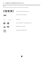
4.2 PROBES :
Isotropic probes
Internal
MF 400
MF 400H
MF 05
EF 400
Measurement
Magnetic field (*)
Magnetic field
Magnetic field
Magnetic field
Electric field
100cm²
100cm²
Equivalent area (10)
Frequency range to 3dB
down (Without filter)
10Hz to 30kHz
10Hz to 400kHz (2)
10Hz to 400kHz (2)
0 to 500Hz
5Hz to 400kHz (5)
Measurement dynamic
range
200nT to 40mT
10nT to 20mT
100nT to 200mT
1µT to 1T
1V/m to 30kV/m
Measurement scales
4/40/400µT/4/40mT
200nT / 2,0 / 20 /
200µT / 2,0 / 20mT
2,0 / 20 / 200µT /
2,0 / 20 / 200mT
200µT, 10mT
and 1T
300V/m,
3 and 30kV / m
Accuracy
± 5% (1) ± 4 digits
± 3% (3) ± 4 digits
± 3% (3) ± 4 digits
± 3% (4)
(6)
Temperature drift
__
± 1%
± 1%
__
± 2%
Band-Pass Filters (11)
+1200 - 2000Hz
+1200 - 2000Hz
+1200 - 2000Hz
+ DC
+1200 - 2000Hz
Power supply
__
none
none
none
Ni-MH or Ni-CD
batteries
7,2V nom.
6,8V min (9)
Battery life
__
_
_
_
6 à 8h (7)
24h (8)
Dimensions
__
425 x 35 / 118mm
425 x 35 / 118mm
316 x 35mm
Sphere - ø 8mm
Length of cable
__
1m
1m
1m
Optical fibre - 5m
Mass
__
400g
400g
260g
300g
(*)
(1)
(2)
(3)
(4)
(5)
(6)
(7)
(8)
(9)
(10)
(11)
See position of internal probe in the unit (pages 6 and 7)
of the reading from 0 to +50 °C
with Wide-Band Filter ; 2 kHz to 400 kHz with High-Pass Filter
of the reading at 23 °C ±3 °C
of full scale between 0 and +50 °C
Band 1 - 10 Hz to 3,2 kHz
5 Hz to 3,2 kHz
Band 2 - RMS 2 kHz HP
2 kHz to 400 kHz
Band 3 - RMS wide-band
5 Hz to 400 kHz
Precision at 23 °C ±3 °C and 50 ± 15% HR
±3 % of reading ±6 least significant digits in Band 1 - from 16 Hz to 2,5 kHz
±5 % of reading ±6 least significant digits in Band 2 - from 10 kHz to 100 kHz with E ≥ 4 V/m
±5 % of reading ±6 least significant digits in Band 3 - from 16 Hz to 100 kHz with E ≥ 4 V/m
in permanent use
in permanent recording mode with a measurement interval of 1mm
Charging time :
10 to 14 h
In conformity with the requirements of standards DIN VDE 0848.
16,6 7 - 50 - 60 - 83,3 - 150 - 180 - 250 - 300 - 400 Hz
5. OPERATING PRINCIPLE
The C.A42 fieldmeter has an internal isotropic magnetic field measurement probe and can use one of the four additional
isotropic
measurement probes (optional):
- MF05, MF400 and MF400 H for the magnetic field,
- EF400 for the electric field.
Remark : The instruement must be switched off when an external probe is connected or disconnected.
The frequency ranges, dynamic ranges, scales, and measurement accuracies depend on the auxiliary probe used, which the
C.A42 automatically recognizes. The C.A42 adapts the values displayed and its configuration parameters to the probe to which
it is connected; if the automatic mode is activated for the choice of range («Auto-range»), then the range that is best suited to the
value measured is chosen automatically.
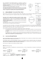
5.1
MEASUREMENT OF A MAGNETIC FIELD
Magnetic fields are measured by the isotropic magnetic field probe built into the instrument or by one of the three external
isotropic probes (MF 05, MF 400, or MF 400 H).
35
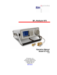
The 3 components of the magnetic field (Hx, Hy, and Hz) in a system of
orthogonal axes (x, y, and z) are sensed by three orthogonal induction coils
mounted in an enclosure, as shown in the installation diagram opposite, for
an MF 400 or MF 400 H.
The directions of the 3 orthogonal measurement reference axes (x, y and z) are
indicated on the marking label attached to each probe.
The voltages induced by the 3 orthogonal induction coils (Vx(t), Vy(t), and Vz(t))
are amplified and digitised by an A/D converter before processing and display.
The MF 400 and MF 400 H probes, which have a measurement area of
100 cm², comply with the requirements of standards DIN VDE 0848.
5.2
MEASUREMENT OF AN ELECTRIC FIELD
Electric fields are measured by the external isotropic electric field probe, EF 400, which has an internal NiMH rechargeable
battery; its sensitivity range can be configured remotely via a 5m optical fibre (change of range).
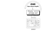
This probe, which is spherical and 80mm in diameter senses, without
deformations, the 3 components of the electric field (Ex, Ey, and Ez) in a system
of orthogonal axes (x, y, and z). The 3 components are measured by three
orthogonal antennas mounted in a spherical enclosure, as shown by the
installation diagram opposite.
A few precautions must be taken to avoid introducing errors when measuring
an electric field.
The shape of the housing in which the measuring antennas are enclosed can
have a large effect on the electric field to be measured.
For example, the 6 faces and 8 edges of a rectangular or cubic housing induce distortions in the measured electric field, and so
systematic measurement errors. Again, any conductor near the measurement point, such as metallic parts or even the human
body, modifies the electric field and so causes measurement errors.
Three important precautions have been taken to eliminate these sources of large errors:
1 - The housing of the EF 400 electric field probe is spherical so as not to induce modifications in the electric field to be
measured;
2 - The measurement is made with the EF 400 probe placed on an insulating support tripod provided as standard with
the probe;
3 - The values of the 3 components of the sensed electric field are transmitted to the measuring equipment via a 5 m
optical fibre so as not to place any conductor near the probe and keep the operator (also a conductor) and the fieldmeter
case, as far as possible from the measurement point.
5.3
CALCULATION METHODS
The C.A 42 fieldmeter receives on its inputs three voltages corresponding to the 3 components of the field measured, whether
electric (Ex, Ey, and Ez) or magnetic (Hx, Hy, and Hz).
The following 3 values, on which all the displays are based, are calculated from these 3 voltages according to the configuration
of the instrument: the RMS value, the peak value, and the phase peak value (or global peak value corresponding to the maximum
maximorum of the several fields at different frequencies interference).
These values are obtained by the following calculation methods:
RMS value = VRMS (x, y, or z)
Where “n” is the frequency, the RMS values on the reference axes (x, y, and z) of a signal having “N” frequency components are
respectively:
The global RMS value of the resultant is
36
Peak value = MAX(x, y, z)
This is the Max value of the amplitude of the equivalent field calculated at the predominant frequency of a composite signal:
Phase (or globale) peak value = Max(x, y, z) ou Min(x, y, z)
These are Max and Min values of the signal resulting from the interference of several fields, e.g. the interference of the 3 electric
fields (Ex, Ey, and Ez) produced, in one place, by 3 sources.
5.4
OSCILLOSCOPE OPTION
This function displays the time variations of one of the components (x, y, or z) of the measured electric or magnetic field, or of the
largest of the 3 components.
The oscillogram, displayed with an automatic or manual amplitude scale, can be triggered in one of 3 modes : automatic, oneshot, or external.
In oscillogram hold mode, this function has 2 markers. One gives the coordinates of any point on the curve and the other
determines a slope - that measured between the positions of the two.
The curve recorded in the storage memory of the C.A 42 is made up of 2,048 points.
5.5
FREQUENCY ANALYSIS (FFT) OPTION
This function is very useful as a way to analyse the harmonic and non-harmonic components of a composite signal. The C.A 42
uses an FFT (Fast Fourier Transform) to calculate the frequency distribution of the signal corresponding to one of the components
(x, y, or z) of the measured electric or magnetic field, or of the resultant of these 3 components.
The calculation, which is based on 2,048 points, gives a result defined at 1,024 points, while only 100 points are displayed; the
points displayed correspond to the root mean square of packets of 10 consecutive points.
The frequency distribution displayed, which has an adjustable frequency step and a “Zoom” function, can be spread.
Also, the amplitude scale of the analysed spectrum can be automatic or manual.
In the spectrum hold mode, a marker (when activated) gives the coordinates of any point of the spectrum.
6. SETTING UP
Power supply:
The C.A 42 fieldmeter uses 5 rechargeable 1.2 V/2300 mAh NiMH AA batteries, located in an interchangeable unit in the bottom
of the instrument, under a protective cover that snaps into place.
IMPORTANT! Check that the internal battery is sufficiently charged for the planned duration of use. The voltage and remaining
charge of the battery are indicated in the “Options/System Information” menu.
The battery unit must be left inside the instrument when recharging. For this purpose, the C.A 42 is delivered with a safety class
II charger, which accepts a line voltage from 100 to 240 VAC. Even so, check that the line voltage suits it.
The charger is connected to the C.A 42 via a coaxial connector on the top of the instrument.
REMARKS:
As long as the charger is connected to the C.A 42, the latter remains On and cannot be switched off.
Charging takes 3 to 4 hours and ends automatically.
Conventional batteries are not rechargeable.
Never connect the charger to the C.A 42 if it is operating on batteries of this type - you could destroy both the instrument and the
batteries!
37
7. MEASUREMENT CONFIGURATIONS
Operating configuration upon power-up:
When switched on, the C.A 42 resumes the configuration it was in when last switched off.
7.1
OPERATING MODES :
The C.A 42 can be configured for four different operating modes, illustrated by the commented screen shots below:
Measurement of a field (electric or magnetic) with permanent display of the measured value,
Comparison of the measured field with the reference value of a Standard, (Weighted measurement),
“Oscilloscope” function with representation of the variations of the measured field versus time, (in option)
Display of the frequency representation of the field, making it possible to analyse the harmonic distribution
(FFT), (in option).
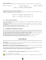
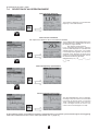
7.1.1
CONTINUOUS MEASUREMENT OF AN ELECTRIC OR MAGNETIC FIELD - (MEASURED VALUE) :
Statut bar (1)
Choice among 6 melorized
norms
RMS value of the measured
field, with the
corresponding unit.
Selection of a type of
filering.
Predominant frequency
of the measured field
Choice of value displayed :
RMS val. - Peak val. Or
Phase (global) peak val.
Memory mode used to save
a measurement
Access to the main
measurement configuration
menus.
Informations
Change of measurement
range (increasing or
decreasing direction)
(1) The «Status Bar» groups the main configuration information :
- The type of measurement made (measured value, oscilloscope function, frequency response, weighted measurement),
- The probe used, Internal or External (MF 400, MF 400 H, MF 05, or EF 400),
- The axis for which the measurement is displayed in the “Oscilloscope” or “Frequency Analysis” mode (X, Y, or Z),
- The status of the internal battery, charging or discharging, with visual estimate of the remaining charge.
00
Example : The status bar of the screen above indicates that the C.A 42 is measuring a magnetic field using its internal probe
(M-Intern) and displays the measured value (Measured val.); its internal battery is charging
.
7.1.2
MEASUREMENT NORMALIZED WITH RESPECT TO THE REFERENCE VALUE OF A STANDARD - WEIGHTED
MEASUREMENT :
Weighted Measurement
Operation on internal
battery
Display of the trend of the
measured value. The
central mark corresponds
to the reference value of
the standard = 100%
Weighted (Normalized) value of
the measured field with respect
tot the reference value of the
selectef Standard.
Choice of one of the 6
stored Standards
Memory mode
Choice of filtering Frequency range in which
the measurement is made.
Value of the field displayed
according to the chosen
calculation method : RMS
val., peak val., Phase (global)
peak val.
Frequency step
Measurement range used
(from 1 to 6)
Measurement «Hold» mode
(bistable function) :
Hold/Run
38
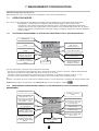
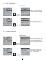
7.1.3
DISPLAY OF THE TIME VARIATIONS OF A FIELD - OSCILLOSCOPE FUNCTION
internal probe used
On figured measurement
function : «Oscilloscope»
Operation on internal battery
(partially discharged)
Adjustment of the trigger level
Variations of the measured field
versus time
Direction of trigger edge
Coordinates of the marked point :
Level/Time or slope between 2
cursors
RMS value
Memory mode
Change of «zoom+/-» value (2)
Selection of the display mode :
«Hold» or «Run»
Change of measurement
scale (2)
This function displays the time variations of one of the components, x, y, or z, of the measured electric or magnetic field, or of the
largest of the 3 components.
Its time base is adjustable from 0.5 ms to 100 ms/div according to the probe used; the level and polarity of the trigger signal are
adjustable.
It is possible to trigger the measurement externally using the “External Trigger” mode, which can be configured from the “Visu”
mode configuration menu.
In Hold mode, two cursors are available: the first gives the coordinates of a point in nT-s or V/m-s, multiples and submultiples;
the second determines a slope, between the positions of the 2 cursors, in mT/s or V/m/s, multiples and submultiples.
In Hold mode, the zoom increases the time base resolution.
(2) A short press on the “V Div” or “Zoom” key changes the measurement range or the value of the zoom in the direction indicated
by the arrow; a long press (approximately 3 seconds) changes the direction of the arrow, and so the direction of variation
(increasing or decreasing).
For the “Oscilloscope” function, the “Zoom” is available in the measurement Hold mode; it is replaced by the time base control
in the continuous measurement mode (Run mode).
7.1.4
DISPLAY OF THE VARIATIONS OF A FIELD VERSUS FREQUENCY - FREQUENCY ANALYSIS (FFT)
The frequency distribution of the harmonic and non-harmonic spectral purity of a composite signal is obtained by calculating an
FFT (Fast Fourier Transform) on 2,048 points, in the following frequency ranges (to 3 dB down): 0 to 29 kHz or 0 to 91 kHz.
The coordinates of a point (nT - Hz or V/m - Hz) are determined using a cursor in the Hold or Run mode.
The display resolution (frequency step) can be chosen from among 1, 1.67, 2, 5, 10, 16.7, 20, 50, and 100 Hz.
Configured measurement function :
«Frequency Distribution (FFT)»
Internal probe used
Representation of the
components of the measured
field as a function of frequency
Coordinates of the point of
intersection of the cursors :
Frequency
Memory mode
Choice of frequency step or
display resolution
Selection of the display mode :
«Hold» or «Run»
Activation of the Zoom +/-
39
7.2
GENERAL CONFIGURATION OF THE C.A 42
In this section, the use of the various functions is presented by the succession of the main screens, with only those comments
specific to the new functions used : comments on the main functions and on how to read the screens were given in the previous
section.
The various screens presented are linked by symbols having the following meanings:
= Use of the keys of the drop-down menu
= Press on the corresponding key
= Next screen
= Use of the «Right» or «Left» displacement keys
= Displacement in the menus
= Validation of the proposed choice
40
7.3
SELECTION OF A MAIN «MENU» :
The C.A 42 is configured by choosing an operating mode and a type od display or of complementary functions, which can be
completed by a choice of specific options, with assistance from a help function matched to the current or selected configuration.
Validation of the choice of
a main menu
Selection of one of the 4 main menus
Operating mode
corresponds to rhe type of
Complementary displays
or functions
Options
On-line information
- Help -
measurement to be made
To make a choice in eath of the main menus
Remark: The «External Trigger» mode is available only for the «Oscilloscope» function (see page 6 - section 3.2); it can
41
be selected in the «Visu» menu.
7.4
SELECTION OF AN OPERATING MODE
Choice of value measured
The frequency displayed is the predominant
frequency of the measured field
ok
Choice of alue normalized
with respect the reference value of the selected standard
The normalized value displayed depends on the
standard selected, e.G. ICNIRP Gen.Pub, and on
the frequency range selected.
(See selection modes page 43)
In the «Weighted Measurement» operating
mode, the value displayed in % is calculed in the
selected frequency range «Freq. 0 to 3,000Hz
in the example show opposite»; the ratio of the
amplitude of each frequency component of the
signal tot he corresponding reference value of
the selected standard is calculated :
ok
Weighted Value (in %) = Σ(f= 0 à Fmax)
{V
(Fi) mesured
/
V(Fi)ref }*100
Choice of frequency representation
ok
Choice of Oscilloscope function
Time base adjustable from 2ms to 400ms/div.
according to the probe used. It can be extended
to 0.1ms/div. by using the “Zoom” in “Hold” and
“Slope” measurement mode; in this mode, the
curve is enlarged around the cursors; the
cursors must be moved again for a slope.
ok
In this operating mode, it is possible to trigger the measurement by an external synchronisation signal; this triggering
mode can be selected from the «Visu» menu (see section 3-2-3 - page 31).
42
7.5
SELECTION OF A DISPLA Y MODE
Measurement of field with X, Y, and Z components
The X, Y, and Z components of the main value
displayed correspond to the calculation mode
selected (e.g. RMS Val.) and depend on the
frequency range chosen.
(See selection modes page 43)
ok
Measurement of field with Min, Max and Mean values
The Min, Max, and Mean values of the main value
displayed correspond to the calculation mode
selected (e.g. Effective val.) and depend on the
frequency range chosen (e.g. 0.01 to 30kHz).
(See selection modes page 21)
ok
Measurement of field with of field with normaliezd value
IN this «measured value / Visu / Weighting»
operating mode, the value displayed in % is
obtained by calculating the ratio of the amplitude
of the component et the predominant frequency
displayed (Freq. 75Hz in the example show
opposite) to the reference value of the selected
standard (Eg. ICNIRP Gen.Pub) at the same
frequency :
Weighted Value (in %) = {V (Fi) mesured / V(Fi)ref}*100
ok
Automatic or Manal measurement scale
In the Weighted (or Normalized) measurement
mode, when «Manual Range» is selected
(by unchecking «Auto Range»), it is possible
to select the range manually, from «Cal 1»,
the most sensitive, to the least sensitive,
«Cal 5» or «Cal 6» .
ok
43
7.6
PARAMETERISING OF THE CURRENT CONFIGURATION
During a measurement, it is possible change the parameters of the configuration used by selecting one of the Parameterising
menus using the “Right” and “Left” direction keys. These modifiable parameters are identified by black triangles pointing down,
and the menu selected is identified by a dotted border.
Selection of one of the modifiable parameters
or
Each press on one of these keys changes the selected
parameter by circular permutation, including the
measurement recording function. The selected function
is highlighted by a dotted border (e.g. Standards ICNIRP Gen.Pub.).
In the selected heading, the parameter is chosen using
the «Up» and «Down» direction keys. The selected
parameter is highlighted by a black background.
ok
44
When the choice is made, the parameter to be selected
is validated by the «OK» validation key.
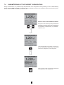
7.7
OPTIONAL CONFIGURATIONS
It is possible to complete the programmed configuration by refining the choice of hidden parameters from the «Options» menu.
Display mode
When the «Standardized Analog Output»
function is checked, the voltages Vx, Vy,
and Vz corresponding to the three
components of the measured magnetic field
(except for the electric field) and available
on the analog output are normalized to 1V at
full scale, in the frequency range from DC to
30kHz, whatever the range selected.
When this function is not checked, the
voltages Vx, Vy, and Vz available on the
output of the measurement probe are
transcribed to the analog output with no
change of level or frequency band
ok
Data acquisition
Choice of recording mode: «Manual» or
«Automatic»; each recording is punctuated
by an audible confirmation.
In “Automatic” recording mode, two
consecutive recordings are separated by a
time interval adjustable from 1 to 999s
ok
The data recording trigger mode can be chosen using the method used to choose a parameter (see “Selection of one of the
modifiable Parameters”page 43).
For “Automatic” recording, the preset time interval between 2 consecutive recordings, chosen in the “Increment” field, is from 1
to 999s.
As an example, for maximum interval of 999s between two records, using the total storage capacity of 1MB, the maximun
possible durations of recording for the various measurements possible are given below.
When the “Measurement point” item is checked, an address in the form A000 (letter plus 3 digits) is associated with each record.
The recording is made in a block defined by the “Top left” address and the “Bottom right” address.
Measurement
Size in memory
Maximum duration
of recording
5,137h = 214d
Measured value
54 Bytes
Weighted measurement
66 Bytes
15 151
2 092 Bytes
478
132h = 5,5d
12 334 Bytes
81
22,5h = 0,94d
Frequency distribution - (FFT)
Oscilloscope
«Linear» recording mode
The progression of recording addresses is “Linear”,
in a sawtooth pattern, from the “Top left” address
(e.g. A000 - A001, etc.) to the “Bottom right” address (e.g. A111);
the letter is then incremented (e.g. B000 - B001, etc.),
and so on.
This option is a convenient way to represent the measurements
in matrix form; indentify the rows and the numbers the columns.
A
B
C
Maximum number
of records
18 515
001
002
003
004
«Meander» recording mode
The progression of recording addresses “Meanders”, in a
triangular pattern, starting with a linear increase from the “Top
left” address (e.g. A000 - A001, etc.) to the “Bottom right” address
(e.g. A111); the letter is then incremented and a linear decrease
follows (e.g. B111 - B110, etc.) and so on.
45
4,204h = 179d
7.8
DATA TRANSMISSION
Datta transmission
This item is used to determine the
number of blocks to be transmitted to
a PC and the set of data to be
transmitted «from: to:».
ok
Errasure of data
Same principle to select the data or
a block of data to be transmitted.
ok
7.9
SYSTEM INFORMATION
System information
Serial no. of the instrument and
identification of the probe currently
used (serial no. and type), available
memory, and remaining battery life.
When an EF400 probe is used, the
remaining life of its internal battery is
given in this menu.
ok
System
Menu used to configure the system,
with: setting of date and time, then
choice of data transmission
parameters.
ok
46
7.10
ON-LINE HELP - “?”
This On-line help - «?» function provides information about the measurements made, in particular about the results and the
display of the measurements, as a function of the current configuration.
Information on the current measurement
Scrolling of the displayed page
using the «Up» and «Down»
direction keys (See «Browser» (7)
§ page 31
ok
Information on the values displayed
ok
Information on the software version and on Chauvin Arnoux
ok
47
8. RS 232 COMMUNICATION
The C.A 42 fieldmeter has as standard a RS232 serial interface that allows it to communicate with a desktop computer (PC)
using its LOG 42 application software.
8.1
CONNECTION :
The C.A 42 is connected to a PC, via the RS232 serial interface, by a special cable provided as standard, reference P01.1673.12.
It has a 9-point D-SUB connector on the PC end and a special 5-pin circular connector, connected to connector no. 5, on the
C.A 42 end (see identification of top panel connectors on page 31).
8.2
CONFIGURATION :
The configuration of the serial link is indicated in the “options/system” menu of the LOG 42.
A data rate from 9,600 to 57,600 bauds can be chosen. The communication protocol can also be selected in this menu; as
standard, it is the following :
8.3
APPLICATION SOFTWARE - LOG 42 :
The C.A 42 is delivered as standard with a CD containing its LOG 42 specific application software, used to import, process, and
save the measurement files stored in the fieldmeter on a PC.
The processing consists essentially in filtering the input files corresponding to the data saved in the fieldmeter, in other words
in selecting and ordering the parameters and the data to be kept in the output file for post-processing.
8.3.1
INSTALLATION :
Place the CD in the drive of the PC and, if installation does not start automatically, start it manually by doubleclicking on “Install.exe”, then follow the instructions given by the successive screens.
8.3.2
USE :
The procedures below are given as examples to help you use the LOG 42 software; to refine your understanding
of the philosophy of use of this software, refer to its help function.
8.3.3
LANGUAGES :
The LOG 42 displays its messages in the leading european languages: French, English, German and Italian.
To choose a language :
- in the “File/Option/General” menu of the LOG 42, choose the desired language.
8.3.4
CONFIGURATION FOR COMMUNICATION :
For communication to be established between the PC and the C.A 42, both instruments must be configured in the same way
(speed and protocol). To ensure this :
- check that the C.A 42 is in fact correctly configured with respect to the PC - “Options/System” menu
In the “File/Option/RS232” menu of the LOG 42, configure the communication interface so that the data rates and protocols are
the same, and choose the appropriate port, generally “COM 1”.
48
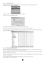
8.3.5
File import procedure :
To display a file stored in the C.A 42 on the screen of the PC, then process it, you must first import it. To do this:
Configure the C.A 42 for “Options/Transmit data”
Choose the number of blocks and their corresponding serial numbers
Configure the LOG 42 for “Data/Receive data”
Name the file to be loaded, then, on the C.A 42, in the first window, press «Start».
The numbers of the blocks transmitted scroll on the PC, in the LOG 42 communication window.
When the transmission is over, the data recovered by LOG 42 are displayed on the PC; the file, once named, is stored in the tree
structure, under “Measurements”.
8.3.6
FILTERING OF IMPORTED DATA :
Generally, when the C.A 42 records a series of measurements, all information necessary for the calculations performed by the
C.A 42, prior to display of the requested quantity is stored at the same time.
When the LOG42 imports a file stored in the C.A 42, all of this information is imported at the same time and is therefore available
simultaneously (see screen shot above).
Therefore, to extract a single class of parameters, you must perform a selection by “filtering” in the complete file. This “Filtering”
operation is described below.
In the tree structure on the left side of the screen, right-click on the name of the file just imported.
Choose “Analysis” in the window that opens.
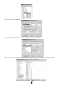
49
In the new window, choose “Outputs”,
and, in the «Output formats» box, choose the configuration of interest by selecting it.
And so on. When you have configured all proposed criteria, click on “Analysis”; the sorted file is displayed on screen.
50
8.3.7
DEFINITIONS :
Below are a few useful definitions intended to facilitate configuring the analysis filters:
- Fieldmeter / Receive data: used to import the files saved in the Fieldmeter to the PC
- Fieldmeter / Enter data: This function acquires and stores the measurements made by the C.A42, which then serves only to
pick up and convert the measurements. The configuration of the Fieldmeter is transcribed on the screen of the PC. The
measurements entered this way are saved in a file declared in the then-active window of the PC.
- Analysis profile:
To carry out an analysis, i.e. to process an imported measurement file on the PC, an analysis profile is used; it may:
- be created just before the analysis is started, in the “Analysis / Analysis…” sequence;
- already exist and be used as is, in the “Analysis / Analyze with…” sequence;
- be created, in the “Analysis / Create analysis profile…” sequence;
- be edited with a view to studying or modifying it, in the “Analysis / Edit analysis profile…” sequence.
The pre-established analysis profiles are stored in the “Analysis profiles” directory.
In the above four particular cases, it is possible to create or modify an analysis profile from the analysis window (see representation
in section 8.3.6 above). The functions of the analysis window corresponding to the tabs are defined in the online “Help” menu of
the LOG42 software; however, a review of a few post-filtering “Output formats” may be useful.
- The “Transposed” output transforms the file analyzed to make it compatible with a spreadsheet (e.g. Excel) by interchanging
the rows and columns.
In this connection, it is possible, once the analysis is finished, to send the new file automatically to Excel or some other postprocessing program, provided that this program has been declared and its access path is specified in the “General” item of the
analysis window.
- The “Matrix” output is useful when the precaution of recording the measurements in the C.A 42 fieldmeter with recording
addresses selected according to the “linear” recording mode has been taken (see section 7.7 - page 19); the rows will
correspond to the letters of the addresses (e.g. B of B021) and the columns to the numbers of these addresses (e.g. 021 of
B021).
- The “Histogram” output is used to obtain the statistical distribution of the measurements among the “Number” of classes
chosen; the “Max.” measured value is entered in the box provided for this purpose.
- The “Versus time” output is used to represent the time course of the measurements stored by the C.A 42.
8.3.8
HELP menu :
The online help function of the LOG42 application software provides the definitions and comments needed for correct use of the
software.
51
9. MAINTENANCE
For maintenance, use only the specified spare parts. The maker is not liable for any accident occurring after a repair not
done by its Customer Service Department or an approved repairer.
Cleaning:
The instrument must be disconnected from all sources of electric power.
To clean the unit, use a cloth slightly moistened with soapy water, then let dry.
Battery charge status:
The voltage and charge of the internal battery of the C.A 42 are indicated in the “Options / System Information” menu (see page
24)
Recharging of the battery
The internal battery of the C.A 42 measurement unit must be recharged using the 230 V / 50 Hz charger provided with the
instrument. Charging takes 3 to 4 hours and ends automatically.
Attention :
As long as the charger is connected to the C.A 42, the measuring equipment remains On and cannot be switched off.
Conventional batteries are not rechargeable. Never connect the charger if the instrument operates on batteries of this type. You
could destroy both the instrument and the batteries!
Note: To preserve the charging capacity, we recommend periodically completely discharging the battery before recharging it
(approximately every 3 weeks).
Replacing the internal battery pack :
We recommend saving the measurement results to the PC before changing the battery pack, because a prolonged absence of
power to the electronic circuits (of the order of 60 seconds) may cause the information stored in the fieldmeter to be lost.
To replace the internal battery pack, you must remove the protective enclosure, then the bottom cover of the instrument.
The cover can be removed by pressing simultaneously on its two grooved sides.
To extract the battery pack, simply press and pull on the tab of the module (see representation of the bottom panel on page 8).
The battery unit must be put back in its housing with its tab upwards; it can be heard to snap into place.
Resetting the C.A 42 :
If the C.A 42 malfunctions, if for example it is impossible to change the configuration of the instrument, it must be reset.
The C.A 42 is reset by proceeding as follows : Press the
and
keys of the browser simultaneously, then the right-hand
key of the drop-down menu keypad for 1 to 2 seconds.
The C.A 42 is then reset; the content of the memory is preserved and measurements resume normally.
If the malfunction recurs after a reset, return the instrument to the manufacturer for repair.
Metrological check
As with all measuring and testing instruments, a periodic check is necessary.
For checks and calibrations of your instrument, contact our COFRAC-accredited metrology laboratories or a MANUMESURE
agency.
Information and coordinates on request: Tel: 02 31 64 51 43
Fax: 02 31 64 51 09
Repair, under warranty or not.
Send your instruments to one of the MANUMESURE regional agencies, which are approved by CHAUVIN ARNOUX.
Information and coordinates on request: Tel: 02 31 64 51 43
Fax: 02 31 64 51 09
Repair outside of mainland France.
For any repair, whether or not under warranty, return the instrument to your distributor.
52
10. TO ORDER
C.A 42 LF fieldmeter
...................................................................................................................................... CA42-CFG
Includes a C.A 42 fieldmeter with an elastomer protective enclosure, a rechargeable battery pack, a 230 V battery charger, a
RS 232 cord, a Trigger cord, an output voltage cord, a carrying bag, LOG 42 application software and a User manual - FR and UK.
Options
Oscilloscope Function
........................................................................................................................... contact us
Frequency analysis function (FFT)
........................................................................................................................... contact us
Certificate of calibration with measurement readings (one certificate per probe) .............................................................. contact us
Accessories
Magnetic field probe
Magnetic field probe
Magnetic field probe
Electric field probe
Replacement battery pack
Small metal storage case
Aluminium tripod
Spares
Small metal storage case
Large metal storage case
Carrying bag
Trigger cord
RS232 cord
230V battery charger
Output analogic voltage cord
MF 400 ............................................................................................................... P01.1673.02
MF 400H ............................................................................................................. P01.1673.03
MF 05 .................................................................................................................. P01.1673.04
EF 400 ................................................................................................................ P01.1673.05
........................................................................................................................... P01.1673.06
........................................................................................................................... P01.1673.07
........................................................................................................................... P01.1673.10
........................................................................................................................... P01.1673.07
........................................................................................................................... P01.1673.08
........................................................................................................................... P01.1673.09
........................................................................................................................... P01.1673.11
........................................................................................................................... P01.1673.12
........................................................................................................................... P01.1673.13
........................................................................................................................... P01.1673.14
53
06 - 2005
Code 691403A00 - Ed.2
Deutschland - Straßburger Str. 34 - 77694 KEHL /RHEIN - Tél : (07851) 99 26-0 - Fax : (07851) 99 26-60
España - C/ Roger de Flor N°293 - Planta 1 - 08025 BARCELONA - Tél : (93) 459 08 11 - Fax : (93) 459 14 43
Italia - Via Sant’ Ambrogio, 23/25 - 20050 BAREGGIA DI MACHERIO (MI) - Tél : (039) 245 75 45 - Fax : (039) 481 561
Österreich - Slamastrasse 29 / 3 - 1230 WIEN - Tél : (1) 61 61 9 61 - Fax : (1) 61 61 9 61 61
Schweiz - Einsiedlerstrasse 535 - 8810 HORGEN - Tél : (01) 727 75 55 - Fax : (01) 727 75 56
UK - Waldeck House - Waldeck Road - MAIDENHEAD SL6 8BR - Tél : 01628 788 888 - Fax : 01628 628 099
Liban - P.O BOX 60-154 - 1241 2020 Jal el dib- BEYROUT - Tél : +961 1 890 425 - Fax : +961 1 890 424
China - Shanghai Pujiang Enerdis Inst. CO. LTD - 5 F, 3 Rd buildind, n°381 Xiang De Road
200081
-
SHANGHAI
-
Tél
:
(021)
65
08
15
43
-
Fax
:
(021)
65
21
61
07
USA - d.b.a AEMC Instruments - 200 Foxborough Blvd, Foxborough, MA 02035 - Tél : (508) 698-2115 - Fax : (508) 698-2118
190, rue Championnet - 75876 PARIS Cedex 18 - FRANCE
Tél. (33 0)1 44 85 44 85 - Télex 269816 - Fax (33 0)1 46 27 73 89