1
EUROPEAN ORGANISATION
FOR THE SAFETY OF AIR NAVIGATION
EUROCONTROL
EUROCONTROL EXPERIMENTAL CENTRE
Mode S TRANSPONDERS TEST BENCHES
FUNCTIONAL REQUIREMENTS
( new version )
EEC Note N° 04/2001
Project MOD-Z-E1
Issued: February 2001
The information contained in this document is the property of the EUROCONTROL Agency and no part should be
reproduced in any form without the Agency’s permission.
The views expressed herein do not necessarily reflect the official views or policy of the Agency.
REPORT DOCUMENTATION PAGE
Reference :
EEC Note N° 04 / 2001
Security Classification :
Unclassified
Originator :
Originator (Corporate Author) Name / Location :
EUROCONTROL Experimental Centre
Centre de Bois des Bordes
B.P. 15
F - 91222 BRÉTIGNY-SUR-ORGE Cedex
France
Telephone : +33 (0)1 69 88 75 00
EEC - COM
(Communications)
Sponsor :
Sponsor (Contract Authority) Name/Location :
EATCHIP Development Directorate
EUROCONTROL Agency
Rue de la Fusée, 96
B -1130 BRUXELLES
Telephone : +32 (0)2 729 9011
DED.3
TITLE :
MODE-S TRANSPONDERS TEST BENCHES FUNCTIONAL REQUIREMENTS
( new version )
Author
Date
Pages
Figures
Tables
Annexes
References
Michel BIOT
02 / 2001
viii + 71
11
5
1
11
EATCHIP Task
EEC Task No.
Task No. Sponsor
Period
Specification
MOD-Z-E1
MOD-Z
-
.
Distribution Statement :
(a) Controlled by :
Head of COM
(b) Special Limitations : None
(c) Copy to NTIS :
YES / NO
Descriptors ( keywords ) :
Mode S, ADS, Test benches, Avionics maintenance
Abstracts :
This note presents user requirements for test tools for Mode A/C/S transponders.
Based on both past experiences in transponder verification and present (and near future) maintenance
necessities, a set of tests is proposed for what should be a minimum Ramp Test set.
A second part develops the tests for Laboratory units, conceived as an extension to the Ramp version.
This document has been collated by mechanical means. Should there be missing pages, please report to:
EUROCONTROL Experimental Centre
Publications Office
Centre de Bois des Bordes
B.P.15
F - 91222 BRÉTIGNY-SUR-ORGE Cedex
France
EEC Note N°
Project
04 / 2001
MOD-Z-E1
Issued : February 2001
Mode S TRANSPONDERS TEST BENCHES
FUNCTIONAL REQUIREMENTS
( new version)
by
Michel BIOT
Summary
Ramp test equipment for Mode A/C transponders exist at present, but generally perform only the
mandatory tests to assure the safe behavior of these avionics, in an environment of Elementary SSR
Surveillance.
There is a need for standardized test tools, for Mode A/C and Mode S transponders, that would execute
defined sets of measurements in defined test conditions so as to give comparable results for all users.
A Ramp version would be necessary for maintenance, and Laboratory versions for repair and research and
development .
Based on multiple experiences of transponder performance measurements, as well as on actual test tools,
the present paper develops the test needs, followed by the functional requirements that should be
discussed with the interested parties before writing technical specifications.
Transponders Test Benches Requirements
v
LIST of ACRONYMS and ABBREVIATIONS
ACAS
Traffic alert and Collision Avoidance System
ADLP
Aircraft Data Link Processor
ADS
Automatic Dependent Surveillance
ADS-B
Automatic Dependent Surveillance-Broadcast
AICB
Air Initiated Comm-B
BDS
Binary Data Store : subfield in MB downlink field
BDS x,x
now renamed GICB register x,x
CMC
Central Maintenance Computer ( of the aircraft )
CMS
Central Maintenance System ( of the aircraft )
GDLP
Ground Data Link Processor
GICB
Ground Initiated Comm-B
GTVS
Ground Transponder Verification System
MOPS
Minimum Operating Performance Specifications
( of the Transponders, edited by EUROCAE)
vi
MTL
Minimum Trigger Level
POEMS
Pre-Operational (development) European Mode S Enhanced Surveillance
STFTV
Surveillance team Task Force for Transponder Verification
XPDR
Transponder ( Mode A/C and Mode S )
Transponders Test Benches Requirements
TABLE of CONTENTS
1
2
3
4
5
PRESENT SITUATION & NEEDS...........................................................1
1.1
Need for Test benches...................................................1
1.2
The Laboratory Test bench.............................................2
1.3
The Ramp Test bench....................................................3
1.4
Combined benches........................................................4
TEST LIST DETERMINATION................................................................5
2.1
Modes A& C Testing History............................................5
2.2
Mode S Characteristics..................................................6
2.3
Latest Requirements.....................................................7
2.4
Global Proposal............................................................7
2.5
List of Procedures for The Ramp Test set...........................8
2.6
List of Procedures for The Laboratory Test set....................9
RAMP TEST SET...............................................................................15
3.1
Procedures Description................................................15
3.2
Ramp Test Program.....................................................30
3.3
Technical Data...........................................................34
3.4
Combined bench.........................................................34
3.5
Testing Environment....................................................34
LABORATORY TEST BENCH...............................................................35
4.1
Procedures Description................................................35
4.2
Bench Test Program....................................................69
4.3
Technical Data...........................................................70
4.4
Testing Environment....................................................70
REFERENCES..................................................................................71
ANNEXE Cross-reference tables / Annex 10 to ED-73A requirements and tests.
Transponders Test Benches Requirements
vii
( blank page )
viii
Transponders Test Benches Requirements
1
PRESENT SITUATION & NEEDS
1.1
N E E D F O R TEST BENCHES
1.1.1
A bit of history
The ramp equipment for XPDR maintenance testing did evolve from totally manual test sets - only capable
of fixed, Mode A/C interrogations (only the spacing P1 - P3 was variable), fixed PRF and SLS conditions,
and few reply analyses (frequency, rough power, % of reply, pulse position of F2 only and acceptance
window for other ones), - up to the present generation in use, capable of measuring under variable
interrogation parameters (pulses, SLS) most of the pulse characteristics (including frequency variations)
with a higher accuracy.
Presently equipment are digitally controlled but through long and semi-automatic procedures. Most ramp
tools in use are variants with capabilities reduced on both interrogations and replies, characteristic and
display; part of the problem is linked to the time limits, to user technicality, to price.
Mode S is now included in these equipment, limited to electrical parameters and some protocols.
1.1.2
Laboratory tests
Several test benches exist for Mode A/C but new bench tools are needed for Mode S XPDRs :
1.1.3
•
to analyse new errors,
•
to investigate new problems, new developments,
•
to examine protocols,
•
to help certify the airborne installation.
Ramp tests
Several ramp test sets exist for Mode A/C & Mode S but
1.1.4
•
they are outdated,
•
they are not yet adapted to
- rapid testing of protocols,
- the increased set of tests (data link functions).
Concerning tests in both situations
Data link function that add new domains of investigation that are only partially fulfilled (e.g. enhanced
surveillance functions) by the test sets presently in use.
European Harmonisation is necessary for both tools and maintenance requirements (for Mode A/C & S
airborne equipment) based on the same EUROCAE MOPS (reference 2).
1.1.5
Some useful references
We refer first to the "Annex 10", the bible of any equipment for SSR and ACAS systems (reference 1 ).
We based the present document initially on an information paper called "Off-line tools for Airborne
Equipment" (see reference 3 ) developed by EUROCONTROL's DED.3 dated Feb 96, philosophy in support
of the IIMSES requesting a coherent bench policy for these equipment, compatible with the future ATN.
Concerning the measurements to be executed in Mode A/C, the following documents are also used:
•
the GTVS (Ground Transponder Verification System) feasibility
•
the STFTV (Task Force on Transponder Verification)
•
an FAA report “ Field Study of Transponder Performance in General Aviation Aircraft (references 7 ).
Transponders Test Benches Requirements
(references 4 & 5 )
(references 6 )
1
1.2
THE L A B O R A T O R Y TEST BENCH
1.2.1
A need for aeronautical administrations research and technical services
These equipment are developed in support of the EUROCONTROL's Initial Implementation Mode S
Enhanced Surveillance Program (IIMSES) which requests a coherent policy be developed for bench
testing of airborne equipment.
Data link, ADLP, ADS-B, ACAS, CMS developers in various European industries may take advantage of
the availability of such a common instrument.
Existing test benches either measure only Mode A/C & S electric characteristics or some protocol but
always off-line. The proposed bench go further in testing systematically all electric parameters and
protocols on-line, giving way to up-down sequences, each reply influencing the next interrogation; these
protocols include Comm A, B, C & D messages.
1.2.2
Test set-up for a complete test bench
Basically, the tests will be executed on the bench, but finally a ramp installation is necessary to validate
“in situ “ the complete airborne chain (incl. antenna), that is, with ACAS, CMC,.. in a real environment " on
the ground " or, simulated, " in the air ".
For this purpose, some extension towards ramp use (power, antenna, physical support) has to be
envisaged. In addition to this operational validation, acceptance of the maintenance procedures will also
use the laboratory benches.
Finally, mixed installations, combining the laboratory bench and a connected ground station can be used
to investigate special problems or new configurations. A setup of this kind exist already between the EEC
and French and UK technical services.
1.2.3
1.2.4
Objectives of the bench
•
validation of SARPS;
•
validation in view of equipment certification (not the certification itself);
•
maintenance validation before delivering the certificate of conformity;
•
evaluation and definition of the maintenance procedures to adopt for each version of airborne
set-up (configurations certification);
•
new investigations & operational evaluations.
Sets of tests
•
Testing is based on ICAO Annex 10, the relevant RTCA & EUROCAE MOPS : signals in space - reply
capability - messages exchange protocols - test conditions (see in Annexe 1 a cross-reference list
between these various documents).
•
Although some equipment will be connected to the XPDR & ADLP, they will not be tested by the
proposed tool, they are only in and output to XPDR & ADLP (e.g. they could be replaced by a bench
controlled airborne data simulator), but the validity of the complete chain will be tested.
•
The lab bench will need 2 parallel units for testing the diversity of both channels of the transponders.
•
Two versions of the lab test bench could be produced, differing by their software size ( and possibly
their "box" ) :
a "complete" version for aeronautical research centres,
another for maintenance labs, using a reduced set of software programs.
2
Transponders Test Benches Requirements
1.3
THE R A M P TEST BENCH
1.3.1
A need for aircraft operators (maintenance services)
Existing Ramp test sets are more or less outdated and cannot support all the requirements of
•
complete set of Mode A/C tests
•
all Mode S protocols
•
BDS, squitter and long squitter validations
and the economy of fast and automatic testing.
1.3.2
A need for administrations (technical services)
The administrations must control
•
the validity of the proposed maintenance requirement
•
the execution of this maintenance.
They need also a mixed form of testing, for validation of different equipment in a pseudo-real environment;
a set-up of this kind exist presently but this subset is not the purpose of the present document.
1.3.3
Objectives of the bench
The first objective being the testing in real conditions of Enhanced Surveillance transponders, the RAMP
test bench has to be developed first, the laboratory equipment being an extension of the ramp unit.
1.3.4
1.3.5
Test conditions
•
Testing is based on ICAO Annex 10, the relevant RTCA & EUROCAE MOPS : signals in space - reply
capability - messages exchange protocols - test conditions (see also Annexe 1).
•
The transponders will be tested in real situation, that is, aboard stationary aircraft, preferably out of the
hangar to avoid reflection.
Availability
New ramp test sets are in preparation, that include automatic sequences; it is highly probable that their
incresed capabilities will join our present request, at least partially. The present document is then a way of
standardising these tools, to reach the minimum commonality.
Transponders Test Benches Requirements
3
1.4
COMBINED BENCHES
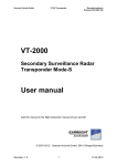
Grouping the various above described benches and taking into account that the ramp unit is basically a
reduced version of the maintenance bench, itself a reduced version of the research bench, one may
propose a common development and the building case like shown on the Figure 1 below
main
RF unit
PC and
display
Airborne
data
simulator
slave
RF unit
main
RF unit
PC and
display
ADLP
XPDR
Figure 1 : Ramp and Laboratory benches for XPDR & ADLP
4
Transponders Test Benches Requirements
2
TEST LIST DETERMINATION
2.1
M O D E A & C TESTING H I S T O R Y (see Table 1 )
2.1.1
Transponder measurements
Starting in 1984, two successive mobile test installations - the MTPA first, and then the DATAS - were built
by EUROCONTROL for measuring transponders either on the bench or aboard aircraft moving on runways
of several European airports.
Thousands of transponders have been measured and statistical data collected, served as support for ATC
surveillance planning. Information on the defective transponders was also transmitted to administrations
and companies, but the follow-up of this procedure was not really engaged.
During the same period, the equipment served as a very useful tool for transponder problem analysis and
for development, investigations and pre-certification of the first European Mode S transponders.
The technology and the use of these equipment are since obsolete, but they form a first base for the
present test definition in Mode A&C.
2.1.2
Automatic testing project
As a follow-up of these equipment, a feasibility study was submitted for an equipment called GTVS
(Ground Transponder Verification System), to be installed on airports for measuring automatically the
transponders aboard the landing aircraft ( see refs. 4 & 5 ).
The required list of tests took into account
•
the results of 5 years of measurements with the MTPA, reporting in particular fault percentages
•
the theoretical consequences of malfunctions
•
the real consequences observed during combined MTPA campaigns ( where MTPA result was linked to
simultaneous radar observations)
•
the administrations reports (" Central Transponder File" )
•
the possibility of automatic measuring and realistic field results.
Trials and theoretical works executed by the study contractors showed that a set of additional
measurements could probably be executed in their GTVS proposal. However, "variable" opinions existed
about the possibility to execute these tests on moving aircraft with valid and operational results.
For the BENCH or RAMP test sets to develop here, the aircraft position is not a problem, and time is not
limited, at least it is not a question of seconds). Therefore, we may consider that ALL the tests developed
in Table 1 are a first minimum for all the benches.
2.1.3
STFTV priorities (see ref. 6 )
The Task Force for Transponder Verification issued in 1995-96 a report that developed considerations and
propositions concerning the verification of transponder behavior in the ATC surveillance environment.
As a conclusion of this task force, periodicity of testing, minimum set of tests and some other
considerations were proposed. They are also included in Table 1.
Transponders Test Benches Requirements
5
2.1.4
Recent FAA field study (see ref. 7 )
A recent field study of transponders aboard General Aviation aircraft in the USA was made using the
modified FAA-DATAS equipment ; made on 548 flying aircraft, the test covered 31 parameters.
The percentage of failures are significantly high if one considers the strict ICAO norms; but they refer to
General Aviation and in particular to aircraft rarely flying IFR.
The study concludes in showing the importance for ATC to test the following parameters : altiude validity,
altitude reporting, delay time difference between Modes, sidelobe suppression vs. P1/P2 ratio, Mode A&C
acceptance vs. P1 & P3 width.
2.1.5
A first list of tests in Mode A/C
The lists of parameters to test, executed or mentioned above, are presented next page in Table 1 , first list
for a Bench Test System, concerning Mode A/C only.
It includes two columns revealing the importance of the measured parameter (theoretical consequences of
malfunctions on ATC), the occurrence of faults during 1984-1988 and 1991-1993 MTPA-DATAS
campaigns.
2.2
M O D E S CHARACTERISTICS
The emergence of Mode S engaged the equipment manufacturers to develop Mode S transponder test sets
some years ago; this generation of tools allows a series of electric characteristics to be tested, combined
with a few essential protocol exchange verifications.
2.2.1
Ramp test set capabilities for Mode A/C/S transponders
The possibilities of presently available ramp test sets are given in Table 2. Due to time limits and some
other considerations (economy, technical difficulties and unawareness of some misbehavior), the full
amount of tests developed in Table 1 is not available or desirable on this sort of tool. (1)
2.2.2
RTCA & EUROCAE documents in Mode S / Intermode
RTCA 's MOPS DO-181A and EUROCAE's MOPS ED-73A (see ref. 2) describe the Mode S transponder
and the tests procedures to ensure the transponder is complying with the ICAO requirements; chapter 3
contains the minimum performance specifications, chapter 5 the tests procedures to be executed in the
laboratory, chapter 6 some additional ones executed on the ramp.
Although not being a maintenance document , but a manufacturing verification / certification test
description, it is used as a main source document for establishing maintenance procedures and rules.
The document being a mandatory reference for the definition of the characteristics, it will serve as such in
the present paper; more, in order not to reinvent the wheel, the protocol procedures will be used directly as
listed in this document (and e.g. their numbering: procedures 1 to 39); these protocol procedures are
shown in Table 3.
6
Transponders Test Benches Requirements
2.3
LATEST REQUIREMENTS
In order to support the Enhanced Surveillance program (see POEMS) and future ADS- applications, the
ramp tool must,
•
analyse long squitters,
•
extract & display in clear all parameters contained in the GICB registers as defined in the
Mode S Specific Service Manual,
•
extract & display in clear AICB messages ( ACAS essential).
The maintenance lab tool must, in addition
•
test all protocols for DATA LINK and some ACAS protocols,
and the research lab tool
•
be able to vary the interrogator's frequency
•
test all ACAS protocols.
2.4
GLOBAL PROPOSAL
2.4.1
Note
To develop new ramp & lab test benches, one has to consider the following points:
2.4.2
•
the research lab tool shall be able to test ALL the parameters defined in the various MOPS mentioned
above
•
the ramp tool shall be able to test all the IMPORTANT parameters, as shown in the above chapter;
JAA43, STFTV and MOPS protocols list contains obligations for ramp testing, but this is far from being
enough
•
to preserve the future, the tools will be able to enlarge their capabilities, at least in the protocol domain.
Procedures
All tests in Tables 1, 2 & 3, plus the equivalent tests in other Modes whenever it applies, are grouped into
test "PROCEDURES" . See the following Tables 4 & 5. ( Hereafter, procedure ° x is labelled " P X " ).
A subset of this “maximum” list is then proposed for the maintenance lab test set; a further reduced list is
then eventually proposed for the Ramp test set.
Each procedure will describe a set of n [ interrogation --> reply ] sequences, that must be carried out to
verify each characteristic or action of the transponder. For the electric tests, it corresponds to n identical
sequences, where n is a function of the required accuracy. For the protocol tests, it is a series of
necessary transactions.
Whenever possible, the procedures adopted in this paper will group several parameter measurements in
one reply (or reply sequence) in order to gain time, especially useful in the Ramp test set. The way chosen
for this grouping allows separation between the tests executed by the ramp test sets and those done in the
laboratory or workshop.
2.4.3
Tests in different modes (electrical characteristics)
The way the characteristic is measured in Mode A&C or Intermode or Mode S may differ not only in the
interrogations patterns and reply data, but also in the importance for ATC or by the fact that the parameter
is already measured under another mode.
This explains the variety of testing between modes and between Ramp / Bench test sets, and also the way
the tests are grouped into procedures.
Transponders Test Benches Requirements
7
2.5
LIST O F P R O C E D U R E S F O R THE R A M P TEST SET
2.5.1
Preamble
The fact that a test or a procedure is proposed for the ramp test set does not implies it is mandatory for
maintenance; the rules are defined by regulation bodies (JAA or others ). The test sets here defined must
at least be able to execute the present ramp imposed tests plus those recently proposed (see above).
2.5.2
Presentation
Some of the tests listed in the Tables 4 and 5 are already executed on the present generation of ramp test
sets. Naturally they include, at least, all what is mandatory in FAR43 for Mode A&C.
The objective is to enlarge the capacity of these equipment to
•
all tests proposed to be mandatory on ramp, in the STFTV report,
•
similar tests in Mode S / Intermodes A&C, whenever it applies,
•
some tests considered as important (see § 2.1) and generally already executable on lab test sets
and/or suggested for bench testing in the STFTV report (see § 2.1.3),
•
protocol tests necessary for long squitter and GICB register extraction, as recently required.
The procedures are listed a s f o l l o w s : P1 to P37 for protocol testing (same numbers as in the MOPS
document), P51 to P87 for electrical parameters testing.
2.5.3
Details
2.5.3.1
Modes A&C parameters
In addition to present equipment’s capability, one adds the tests
•
pulse amplitude variation,
•
delay time difference Mode A vs. Mode C,
•
Mode A code validity, Mode C height validity (on the ground value),
•
reply rate at various PRF instead of only 235 Hz or 500 Hz,
•
Mode A & C acceptance vs. P1 >> P3 spacing;
all tests that can be easily implemented.
Test 4 was presently limited to the F2 position; the offset of ALL pulses should be verified and the
maximum value (in fact, the worst) displayed.
2.5.3.2
Intermodes A&C parameters
The Intermode A&C acceptance vs. P4 short or long pulse is enlarged to a complete test, the acceptance
vs. P4 width.
Important also is the test T32, Intermode A&C acceptance vs. P3 >> P4 spacing.
2.5.3.3
Mode S - electric parameters
Are added to the present test sets possibilities:
•
pulse positions (mean offset is enough here),
•
pulse amplitude variation from the 1st to the 56th or 112 th, ,
•
mean pulse width,
•
mixed reply rate capability (a complex series of various interrogations at various rates),
•
Mode S acceptance vs. P1 >> Sync. Phase Reversal spacing.
All these tests are important for a correct decoding (a 112-bit long message is much more sensitive to a
deviating clock than a 12-bit in the Mode A reply); including the Sync Phase Reversal, where the
acceptance of the P2 >> P6 spacing should be verified inside a large window and not just limited to YES or
NO at nominal time.
8
Transponders Test Benches Requirements
The squitter verification in Mode S is included in the protocol procedures (a complex combination of short
and long squitters whose contents vary in accordance to GICB / Mode S Specific Service Manual).
It is not possible to test on the ramp (that is, without cable connections) the diversity parameters, the two
antennas receiving simultaneously the signals, albeit with very small time delay and power difference.
2.5.3.4
Mode S protocols - compared to EUROCAE MOPS
The test procedure n° 1 ( “P1” ), Error Protection, is not possible with a XPDR installed in an aircraft, the
address being “cabled” in the rack. Only the correct address will be verified as part of any other tests.
Test procedure P 3, the capability, and P 8, the PI verification, are checked in the replies DF11 in P 2 .
Squitter verification protocol n° 6 : these last years, the squitter protocols (simple and extended) have
changed and may change further, since their increasing role in ATC. The ramp test bench shall be built
such as only to accept and analyse the various squitter periodicity ( P 6 ) .
Mode S addresses are tested in various combinations to discover e.g. incorrect cabling or bad contact in
the transponder rack mounting ( procedure P 9 ).
Procedure 1 0 verifies the altitude reports, but this depends on the installation possibilities.
Procedure 1 1 corresponds to the Mode A code validity executed on Mode A&C transponders, but
contained here in a Mode S downlink messages; the importance is therefore the same.
Aircraft identification and stochastic behavior of the transponder are important data for a smooth radar
behavior; these characteristics are easily tested in procedures 1 2 & 1 3 .
Comm-B messages are important in the exchanges between ground and aircraft, for various reasons,
including ADS; they are not mandatory for all levels of transponders; more, some characteristics are not
yet adopted neither definitive. But many BDS (see Mode S Specific Services) are already defined and they
are included in the Basic and Enhanced Surveillance Functionalities. Therefore a new procedure P 1 7
concerning the GICB registers is developed for ramp testing.
Finally, an ACAS detection capability test ( P35) seems useful in the ramp version.
2.5.4
Proposed List of Procedures
Finally, the following list of procedures is proposed for the Ramp Test set :
Mode A&C
2.6
:
procedures P 5 1 , 5 2 , 5 3 , 5 7 , 5 8 , 6 2 & 6 6 .
Mode S and Intermode A&C :
procedures P 7 1 , 7 2 , 7 5 , 7 7 , 8 5 , 8 6 & 8 7 .
Mode S Protocol
procedures P 2 , 6 , 9 , 1 0 , 1 1 , 1 2 , 1 3 , 1 7 & 3 5 .
:
LIST O F P R O C E D U R E S F O R THE L A B O R A T O R Y TEST SETS
This version of the test set is of course much more complete as well as more flexible, because different
types of users are interested.
For research centres, the complete list of procedures developed in the
Tables 4 & 5
should be
executable; this is developed in chapter 4. For maintenance labs, the set of tests (of procedures) will be
reduced to those mandatory plus some easily executable; their list will be defined later, it is a subset of
the complete list.
Mode A&C
:
procedures P 5 1 t o 6 7 .
Mode S and Intermode A&C :
procedures P 7 1 t o 8 7 .
Mode S Protocol
procedures P 1 t o 2 8 ( there are no P 3, P8, P14 )
:
(other ACAS tests are reserved for a later version of this document).
Transponders Test Benches Requirements
9
Table 1
:
FIRST SERIES of MODE A/C TESTS
MTPA
Transponder's transmission
characteristics (1090 MHz )
+
GTVS
FAA
STFTV
importance
importance
importance
requirements
3.8 / 2.0
XXX
XXX
XX
F
4.6 / 1.9
XX
XX
F
mean failure
occurrence (%)
DATAS
84-88 / 91-93
1 - reply frequency
2 - mean output power
3 - pulse amplitude variation during a reply
.
XX
XX
-
4 - pulse positions : max offset
“
“
: mean offset
1.9 / 1.8
XX
XXX
XXX
XXX
SA
5 - pulse width (mean of all pulses)
4.7 / 1.8
XX
XX
XX
SB
XX
-
XX
XXX
F
XX
X
SB
6 - Mode A code validity
.
-
7 - Mode C : altitude report
“
“ on the ground
8 - delay time,
delay time jitter
- /
-
(a)
(a)
3.0 / 0.8
-
X
-
9 - delay time difference Mode A vs. Mode C
XXX
10 - delay time vs. input level
-
11 - squitter periodicity (no interrogations)
12 - reply pulse rise & decay times
13 - reply rate vs. PRF
@ 235 Hz
@ 500 Hz
.
Receiver parameters
-/
XXX
-
X
-
0.8
x
xx
(a)
(a)
X
-
XX
-
F
SA
(1030 MHz )
21 - MTL Mode A, Mode C
.
MTL difference Mode A vs. Mode C
22 - dead time
23 - suppression time
- /
- /
≈0 / 0.7 / 0.6
26 - sidelobe suppression vs. P1 >> P2 spacing
27 - sidelobe suppression vs. P2 pulse width
28 - interference (additional P1* - P1 - P3 )
29 - Mode A acceptance vs. P1 >> P3 spacing
.
idem Mode C
30 - Mode A&C acceptance vs. P1 & P3 width
X
XXX
0.8 / ≈ 0
4.7 / 0.8 (b)
XX
≈0 / (a)
F
X
-
24 - receiving frequency acceptance
25 - sidelobe suppression vs. P1 / P2 level ratio
X
X
XX
F ( 0 &9 dB)
XXX
SB
-
/-
0.6 / 2.3
1.4 / 2.1
XX
XX
X
X
0.3 / 16.3 (c)
X
X
SA
SA
X
SB
not measured
a
few measurements only; not statistically significant
b
one old series of transponder showed some strange behavior
c
one or two old series of transponder reacted to very short P1&P3 pulses (< 200 ns )
X, XX, XXX by increasing importance
F
FAR 43 mandatory biennial Ramp test ; included in STFTV
SA
STFTV addition to the FAR 43 requirements, for Ramp testing
SB
STFTV supplementary addition for Bench testing.
Test numbering ( 1 to 33) ; see note bottom of Table 2 next page
10
Transponders Test Benches Requirements
Table 2
:
PRESENT RAMP TESTER CAPABILITIES
Transmission parameters (1090 MHz )
Mode A/C
Intermodes
Mode S
1 - reply frequency
Y
Y
Y
2 - mean output power
Y
Y
Y
4 - pulse positions : mean offset
Y
5 - pulse width (mean of all pulses)
Y
8 - delay time , delay time jitter
Y
Y
Y
11 - squitter periodicity
na
na
Y
15 - diversity isolation
na
Receiver parameters
Y
(1030 MHz)
21 - MTL all Mode s
Y
Y
Y
25 - sidelobe suppression vs. P1 / P2 level ratio
. ( in Mode S : " "
vs. P5 / P6 level ratio
Y
na
Y
na
/
31 - Intermode A&C acceptance vs. P4 width
.
Intermode A&C only All-Call
na
Y
(Y) (1)
32 - Intermodes acceptance
.
vs. P3 >> P4 spacing
na
na
33 - Mode S acceptance
.
vs. P2 >> Sync Ph.Rev. spacing
na
na
-
(Y)
On / Off only
Messages control Up / Down
- uplink address control
Y
- long squitter
Y
- UF 4
Y
- UF 5
Y
- UF 11 / Mode S Only All-Call
na
na
Y
- UF 16
Y
- UF 20
Y
- UF 21
Y
- Comm - A
limited (2)
- Comm - B
limited (2)
- Comm - C
- Comm - D
Note
Y
yes, available
n a not applicable to this Mode
(1) should not reply
(2) in octal; Comm-A only MA field programmable, limited and uneasy,
Comm-B difficult to extract the GICB registers (BDS) .
For the sake of cross-reference, the test numbers (first column) are common to Tables 1,2 & 4 ;
n° 1 15 : electrical characteristics of the transponder's transmission (1090 MHz )
n° 21 33 : electrical characteristics, transponder's reception capability (1030 MHz)
no numbers for the message / protocol tests, as they will be regrouped with the MOPS procedure tests that follow.
Transponders Test Benches Requirements
11
Table 3
:
MOPS ED-73A ,
Procedures
PROTOCOL PROCEDURES
MOPS
procedure
number
XPDR
level
Laboratory
tests
Error protection
1
ALL
Y
Interrogation acceptance
2
ALL
Y
Y
Y
CA verification
(3 : in 2 )
ALL
Y
Non-selective lockout
4
ALL
Y
Selective lockout
5
ALL
Y
Squitter verification
6
ALL
Y
FS & VS protocol / code
Parity - identity (PI) verification
Address verification
Ramp
tests
Y
7
ALL
Y
(8 : in 2)
ALL
Y
Y
9
ALL
Y
Y
Altitude report
10
ALL
Y
Y
4096 code
11
ALL
Y
Y
RI, acquisition & maximum airspeed
12
ALL
Y
PR reply probability, stochastic acquisition
13
ALL
Y
Comm-A, interface & information content
15
2
Y
16
2
Y
(17 : in 18)
2
Y
Y
Broadcast All-Call formats
(uplink)
Downlink interface DF 0, DF 16
Comm-B protocol
18
2
18A
(2)
AIS flight ident protocol & interface
19
2
Y
Basic / extended capability report
20
2
Y
Enhanced Comm-B protocol
Directed Comm-B
21
2
Y
21A
2
Y
Downlink interface, storage design, buffer rate
22
2
Y
Downlink interface, no-storage design
23
2
Y
Comm-C protocol
24
3
Y
Uplink interface, ELM Comm-C
25
3
Y
Y
Comm-B broadcast
Comm-D protocol
26
4
26A
(4)
Directed Comm-D
27
4
Y
Comm-D interface, rate & content
28
4
Y
Comm-U uplink interface
29
2
Y
Sensitivity level operation
30
ACAS
Y
RA report to Mode S ground interrogator
31,31A,31B
ACAS
Y
Transmission of ACAS capability information
32,32A,32B
ACAS
Y
ACAS or XPDR/ACAS failure during transmission
33
ACAS
y
Coordination
34
ACAS
Y
ACAS broadcast message
35
ACAS
Y
XPDR replies to incoming ACAS resolution mess.
36
ACAS
Y
XPDR / ACAS throughput
37
ACAS
Y
XPDR communication timing
38
ACAS
Y
ACAS crosslink
39
ACAS
Y
Enhanced Comm-D protocol
Y
Y
Numbers in brackets means the parameter can be tested during another procedure in order to reduce the total measurement time
12
Transponders Test Benches Requirements
Table 4
:
MAXIMUM T E S T LIST - ELECTRICAL PARAMETERS
All XPDRs
Transponder's transmission
characteristics (1090 MHz
Mode S XPDRs only
Mode
A/C
procedure
Intermode
Mode
S
procedure
1 - reply frequency
X
X
X
P71
2 - mean output power
X
P51
P52
X
X
P72
3 - pulse amplitude variation during a reply
√
XX
XX
4 - pulse positions : max & mean offset
X
√
√
5 - pulse width (mean of all pulses)
√
√
6 - Mode A : code validity
√
7 - Mode C : altitude
√
8 - delay time , delay time jitter
XX
9 - delay time difference Mode A vs. Mode C
XX
√
see P11
see P10
P53
√
√
P73
10 - delay time , delay time jitter
√
P54
11 - squitter periodicity
√
P55
-
12- reply pulse rise & decay times
√
P56
-
√
P73
13 - reply rate vs. PRF
X
P57
14 - mixed reply rate capabilty Mode A + S
-
XX
P75
15 - diversity isolation
-
X
P76
see P6
Receiver capabilities (1030 MHz )
21 - reveiver dynamic range (MTL) all Modes
X
P58
X
X
P77
22 - dead time
√
P59
√
√
P78
23 - suppression time
√
P60
-
√
P79
24 - receiving frequency acceptance
√
P61
-
√
P80
25 - sidelobe suppression vs. P1 / P2 level ratio
( in Mode S : " "
vs. P5 / P6 level ratio
X
P62
26 - sidelobe suppression vs. P1 >> P2 spacing
√
P63
27 - sidelobe suppression vs. P2 pulse width
√
P64
28 - interference (additional P1* -P1-P3)
√
29 - Mode A&C acceptance vs. P1>> P3 spacing
30 - Mode A&C acceptance vs. P1 & P3 spacing
-
√
P81
√
-
P82
P65
-
√
P83
X
P66
√
-
P84
√
P67
31 - intermode A&C acceptance vs. P4 width
X
-
P85
32 - intermode A&C acceptance vs. P3 >> P4 spacing
√
-
P86
33 - Mode S acceptance vs. P2 >> SyPhRev spacing
-
X
P87
Legend
- not applicable
applicable
X id, mandatory and/or recommende by STFTV + test similar in Mode S
XX id, and/or important for ATC >> to be executed also by the ramp test set
In BOLD OBLIQUE : procedures for the ramp test set (see 2.5.4)
Test numberingin the first column (1 to 33) : see note bottom of Table 2.
Transponders Test Benches Requirements
13
Table 5
: MAXIMUM TEST LIST - PROTOCOLS
Procedures
MOPS
number
XPDR level
applicable
procedures
Error protection
1
ALL
Interrogation acceptance
2
ALL
P 2
P 1
(3)
ALL
use instead tests P2 & P6
Non-selective all-call lockout
4
ALL
P 4
Multisite Selective lockout
5
ALL
P 5
Squitter verification
6
ALL
P 6 red / P 6
CA verification
FS & VS protocol / code
7
ALL
P 7
(8)
ALL
results obtained in tests
P2, P4 & P5
Address verification
9
ALL
Altitude report
10
ALL
4096 code (code set)
11
ALL
P 9
P 10
P 11
RI, acquisition & maximum airspeed
12
ALL
P 12
PR reply probability, stochastic acquisition
13
ALL
P 13
Comm-A, interface & information content
15
2
P 15
Broadcast All-Call formats
16
2
P 16
(17)
2
results obtained in test P18
-
2
P 17
18
18A
2
P 18
GICB regiter extraction & interface,
Incl. AIS flight ident & other BDS
19
2
P 19
Basic / extended capability report
20
2
P 20
Directed Comm-B
21
2
P 21
Parity - identity (PI) verification
(uplink)
Downlink interface DF 0, DF 16
GICB register extraction / decoding only
Comm-B protocol
Enhanced Comm-B protocol
Comm-B broadcast
21A
Downlink interface, storage design, buffer rate
22
2
P 22
Downlink interface, no-storage design
23
2
P 23
Comm-C protocol
24
3
P 24
Uplink interface, ELM Comm-C
25
3
P 25
26
26A
4
P 26
Directed Comm-D
27
4
P 27
Comm-D interface
28
4
P 28
Comm-U uplink interface
29
2 , ACAS
Sensitivity level operation
30
ACAS
RA report to Mode S ground interrogator
31,31A&B
ACAS
Transmission of ACAS capability information
32,32A&B
ACAS
ACAS or XPDR/ACAS failure during transmission
33
ACAS
Coordination
34
ACAS
ACAS broadcast message
35
ACAS
XPDR replies to incoming ACAS resolution mess.
36
ACAS
XPDR / ACAS throughput
37
ACAS
XPDR communication timing
38
ACAS
ACAS crosslink
39
ACAS
Comm-D protocol
Enhanced Comm-D protocol
Note :
14
P 35
In BOLD OBLIQUE ; procedures for the Ramp Test set ( see 2.5.4 ).
Transponders Test Benches Requirements
3
RAMP TEST SET
3.1
PROCEDURE DESCRIPTION
There are 3 groups of procedures :
•
Mode A&C procedures ( § 3.1.1 )
•
Mode S & Intermode A&C electrical procedures ( § 3.1.2 )
•
Mode S protocol procedures ( § 3.1.3 )
Legend
1 - MS = Eurocae MOPS ED-73A (see ref. 2) for SSR transponders
: performance specifications (its § 3.2 ...);
MT =
"
"
"
: test procedures data (its § 5.4 & 5.5.8 );
It is useful to refer also to the Cross-Reference table in Annexe,
which gives the relevant ICAO-Annex10paragraphs.
2 - Mean: in the 3 paragraphs 3.1.1 to 3.1.3, all values are computed as the mean of
100 replies (100 identical [ interrogation--reply ] sequences);
Time spacing are counted from the pulse front edges, at half-amplitude.
3 - Unless otherwise stated,
- PRF is 450 Hz for Mode A&C and 50 Hz for Intermodes and Mode S;
- When maximum load is requested, Mode A code is set to 7377 (+ the SPI if necessary)
because the highest load code (A 7777) could mislead safety on radar’s in the vicinity;
- When a variation between successive bits is desirable, A 1642 is used.
4 - The sign
means in a sequence : the interrogation followed by its reply.
5 - The sign Q shows settings on the transponder side (fixed and / or modified during the test )
that is entered or executed by the “ pilot “.
Note
Procedures P58 & 77, measuring the MTLs, must be executed before the other Receiver Capability tests
(58 before 59 to 66, and 77 before 80 to 87 ) that need the MTL values.
So, it is recommended to follow simply the numerical order ( 51 to 66, 71 to 87, 2 to 19 ) in the automatic
sequence (see 4.2.4 for more details).
Transponders Test Benches Requirements
15
3.1.1
Mode A&C Procedures
Procedure
a
P 51
Verification
Reply Frequency.
b
Performance specifications
MS 3.3.1 - MT 5.4.2.1.
c
Fixed settings
interrogator at nominal setting; level at XPDR input : -50 dBm; Mode A.
Q XPDR code : A 7377 + SPI.
d
Test progress
100 [ interrogation
e
reply ] sequences.
Measurement & display
Frequency ( 1090 MHz ): mean value of all pulses.
Procedure
a
P 52
Verification
Mean Output Power, Pulse Amplitude Variation, Mean Pulse Width, Pulse Positions,
Mode A pulse decoding.
b
Performance specifications
MS 3.3.3, 3.5.1 to 6 -
c
MT 5.4.2.2, 5.4.3.1 .
Fixed settings
Interrogator at nominal setting; level at XPDR input : -50 dBm; Mode A.
d
Test progress
reply ] sequences with Q XPDR set to code A 7377
100 [ interrogation
repeated with successively Q codes A 4000 and A 0400.
e
Measurement & display
Reply code displayed;
for each code:
power : . . . . . . mean value of all pulses / mean value of lowest pulse
maximum variation between all pulse in a reply (min-max).
position of ALL pulses (vs. F1 + n x 1.45 µs ) : mean value of each pulse
and the maximum offset (that is, the offset of the “worst” pulse)
pulse width : . . mean value of all pulses.
16
Transponders Test Benches Requirements
Procedure
a
P 53
Verification
Delay Time, Delay Time Jitter, Delay Time Difference Mode A vs. C, Code C .
b
Performance specifications
MS 3.7.1 , Annex 10 (Gilham conversion ) -
c
MT 5.4.3.3 .
Fixed settings
Interrogator at nominal setting; level at XPDR input : -50 dBm .
d
Test progress
100 [ interrogation
reply ] sequences in Mode A; idem Mode C
Q XPDR code A 1642, altimeter switched out if possible;
( if not : the altimeter will correspond to the “ground altitude”).
e
Measurement & display
Delay time (P3 >> F1) : mean value Mode A and Mode C are compared ;
jitter on delay time σ of 100 replies );
reply altitude decoded (either C 0000 or xxxx, corresponding to -1000 ft or to “ground altitude”).
Procedure
a
P 57
Verification
Reply Rate vs. PRF.
b
Performance specifications
MS 3.4.1 -
c
MT 5.4.2.5 .
Fixed settings
Interrogator at nominal setting; level at XPDR input : -50 dBm
Q XPDR code : A 7377 + SPI .
d
Test progress
PRF 500 interrogations per sec during one sec, followed by 5 or 10 sec rest,
then idem at 600, 700, . . . 1500 interrogations per sec.
e
Measurement & display
Diagram : reply % vs. PRF.
Transponders Test Benches Requirements
17
Procedure
a
P 58
Verification
Mode A & C Sensitivity (MTL).
b
Performance specifications
MS 3.2.4 -
c
MT 5.4.1.2 .
Fixed settings
Interrogator at nominal setting;
Q XPDR code : A 1642, altimeter at zero if possible;
(if not : the altimeter will correspond to the “ground altitude”).
d
Test progress
100 [ interrogation
reply ] sequences, level at XPDR input : -60 >> -80 dBm, per 1 dB steps
first with Mode A, then repeated using Mode C.
e
Measurement & display
Diagram : reply % vs. input power; MTL = interrogator’s level when reply rate crosses 90 %
MTL difference Mode A <-> C displayed.
Procedure
a
P 62
Verification
Sidelobe Suppression vs. P1 / P2 Level Ratio.
b
Performance specifications
MS 3.8.2 - MT 5.4.4.1 .
c
Fixed settings
interrogator at nominal setting;
Q XPDR code : A 1642, altimeter at zero if possible;
(if not : the altimeter will correspond to the “ground altitude” ).
d
Test progress
With a P2 at nominal position & width, P2/ P1 ratio varying from -12 dB >> + 3 dB, per 1 dB steps
100 [ interrogation
reply ] sequences for each step
repeated for the level at XPDR input : -50 dBm & MTL + 3 dB.
e
Measurement & display
Diagram : reply % vs. P2 / P1 ratio, tolerance areas shown (for the 2 input power levels).
Reduced version (if available time is too short) : replace the diagrams by reply % at -9.0 dB and 0 dB only.
18
Transponders Test Benches Requirements
Procedure
a
P 66
Verification
Mode A & C Acceptance vs. P1 >> P3 Spacing.
b
Performance specifications
MS 3.9.3 - MT 5.4.5.2.
c
Fixed settings
Interrogator at nominal setting;
Q XPDR code : A 1642
d
Test progress
P1 >> P3 spacing varying from 6.5 >> 9.5 µs and 19.5 >> 22.5 µs, per 25 ns steps
100 [ interrogation
e
reply ] sequences for each step.
Measurement & display
Diagram : reply % vs. P1 / P3 spacing, tolerance areas shown
for both Mode A ( 6 >> 10 µs ) and Mode C ( 19 >> 23 µs ).
Reduced version (if available time is too short) : replace the diagrams by a set of values;
reply % at -7.0, 7.8, 8.2, 9.0 µs and 20.0, 20.8, 21.2, 22.0 µs only.
3.1.2
Modes S and Intermode A&C Electrical Procedures
Procedure
a
P 71
Verification
Reply Frequency.
b
Performance specifications
MS 3.3.1 - MT 5.4.2.1.
c
Fixed settings
Interrogator at nominal setting; PRF 50 Hz; level at XPDR input : -50 dBm;
Q XPDR code : A 1642.
d
Test progress
100 [ interrogation UF 05
or [ Intermode A
e
reply DF 05 ] sequences
reply DF11 ] sequences.
Measurement & display
Frequency ( 1090 MHz ) : mean value of all Mode S pulses.
Transponders Test Benches Requirements
19
Procedure
a
P 72
Verification
Mean Output Power, Pulse Amplitude Variation, Mean Pulse Positions, Mean Pulse Width.
b
Performance specifications
MS 3.3.3, 3.6.1 to 3.6.6 -
c
MT 5.4.2.2, 5.4.3.2 .
Fixed settings
Interrogator at nominal setting; level at XPDR input : -50 dBm;
Q XPDR code : A 1642.
d
Test progress
100 [ interrogation UF 05
or [ Intermode A
e
or 21*
reply DF 05 or 21* ] sequences
reply DF11 ] sequences.
Measurement & display
Frequency ( 1090 MHz ) : mean value of all Mode S pulses.
power : . . . . . . mean value of all Mode S pulses
+ diagram : amplitude of each reply datapulse (1st >> 56th or 112 th * ).
pulse position : mean offset (nominal vs. 1st pulse + (0.5 x n) µs )
pulse width: . . .mean value of, separately, the preamble pulses, the 0.5 µs pulses & the 1 µs pulses.
Note * : depending on the capability of the transponder.
Procedure
a
P 75
Verification
Mixed Reply Rate Capability.
b
Performance specifications
MS 3.4.2 -
c
MT 5.4.2.5 .
Fixed settings
Interrogator at nominal setting; level at XPDR input : -50 dBm;
Q XPDR code : A 7377 + SPI.
d
Test progress
4 separated sequences lasting 1 sec each :
a - 500 interrogations Mode A uniformly mixed with 50 UF 05 interrogations * in 1 s
b - 120 interrogations Mode A uniformly mixed with 18 UF 05 interrogations * in 0.1 s,
followed by 0.9 s rest
c - 30 interrogations Mode A uniformly mixed with 8 UF 05 interrogations * in 0.025 s,
followed by 0.975 s rest
d-
2 interrogations Mode A uniformly mixed with 4 UF 05 interrogations * in 0.0016 s,
followed by 0.9984 s rest .
note * : if the XPDR is equipped for long replies, respectively 16 of the 50, 6 of the 18,
4 of the 8 and 2 of the 4 interrogations must require long replies.
e
Measurement & display
The XPDR must reply to ALL these interrogations.
20
Transponders Test Benches Requirements
Procedure
a
P 77
Verification
Intermode A/C and Mode S Sensitivity (MTL).
b
Performance specifications
MS 3.2.4 -
c
MT 5.4.1 .
Fixed settings
Interrogator at nominal setting;
Q XPDR code : A 1642, altimeter at zero if possible;
(if not, the altitude will correspond to the "ground altitude" ).
d
Test progress
- 100 [ interrogation Intermode A
reply DF11 ] sequences,
level at XPDR input : -60 >> -80 dBm, 1 dB steps;
- repeated for Intermode C.
- 100 [ interrogation UF 11 (with PR = 0)
reply DF 11 ] sequences,
level at XPDR input : -60 >> -80 dBm, per 1 dB steps.
e
Measurement & display
Diagrams : reply % vs. input power; MTL = interrogator’s level when reply rate crosses 90 %.
MTL difference Mode A ⇔ C displayed
(for MTL + 3 dB and higher, the reply rate must be 99 %).
Procedure
a
P 85
Verification
Intermode A/C Acceptance vs. P4 width.
b
Performance specifications
MS 3.9.4 -
c
MT 5.4.5.2 .
Fixed settings
Interrogator at nominal setting; no P2;
Q XPDR code : A 1642, altimeter at zero if possible;
(if not, the altitude will correspond to the "ground altitude").
d
Test progress
Level at XPDR input : -21, -40 & -60 dBm
P4 varying from 1.0 >> 3.0 µs, per 25 ns steps
100 (interrogation
e
reply) sequences for each step and each input level.
Measurement & display
Diagram : reply % vs P4 width, tolerance areas shown
for both Intermode A & C and for each of the 3 input levels.
Transponders Test Benches Requirements
21
Procedure
a
P 86
Verification
Intermode A/C Acceptance vs. P3 >> P4 Spacing.
b
Performance specifications
MS 3.9.3 -
c
MT 5.4.5.2 .
Fixed settings
Interrogator at nominal setting; no P2;
Q XPDR code : A 1642, altimeter at zero if possible;
(if not, the altitude will correspond to the "ground altitude" ).
d
Test progress
Level at XPDR input : -21, -40 & -60 dBm
P3 >> P4 spacing varying from 1.4 >> 2.7 µs, per 25 ns steps
100 [interrogation
e
reply ] sequences for each step & each input level.
Measurement & display
Diagram : repy % vs. P3 >>P4 spacing, tolerance areas shown
for both Intermode A & C and for each of the 3 input levels.
Procedure
a
P87
Verification
Mode S Acceptance vs. P2 >> P6 (Sync. Phase Reversal) Spacing.
b
Performance specifications
MS 1.6.4, 3.9.5 -
c
MT 5.4.5.2 .
Fixed settings
Interrogator at nominal setting;
Q XPDR code : A 1642.
d
Test progress
P2>> Sy. Ph. Rev. spacing varying from 2.4 >> 3.1 µs, per 25 ns steps;
level at XPDR input : MTL +3 dB and -50 dBm ;
100 [ interrogation
e
reply ] sequences for each step for each power level .
Measurement & display
Diagram : reply % vs. P2 >> Sync. Phase Reversal spacing, tolerance areas shown,
both level curves shown.
22
Transponders Test Benches Requirements
3.1.3
Mode S Protocol Procedures
Note
For all the protocol tests, the interrogator is at nominal regarding “electric” values; no pulse P2 is used;
level at XPDR input is -50 dBm; uplink address is the XPDR address; XPDR code is A 7377.
Unless especially mentioned.
Some test are only applicable to some types of XPDRs, depending on their level (see third column in
table 5) or whether they are “Mark 4 “ or not (see the double asterisks **); for this last type of
transponders, see reference 8
"Transponders with extended interface functions (Mark 4)".
For these ramp tests, diversity operation must be inhibited to avoid unequal, unknown reception by the
XPDR and “jumping” problems : the power and delay differ, and, worse, the upper antenna may be totally
invisible to the test set located on the ground; or simpler, the test set ignores which antenna is replying;
therefore, the top channel must be terminated by its characteristic impedance.
Successive signs
mean a sequence containing more than 1 interrogation followed by 1 reply.
Attention
The Mode S Specific Services as well as the squitter protocol may still change in the near future; so, in
some of the protocol tests (see : “ ATTENTION : THE SPECIFICATIONS MAY VARY”), the BDS
definition, their use, the sequences, and the repetition rate (if applicable) may be different from what is
developed; but the principle of the measurement remains. Always refer to the latest version of the Mode
S Specific Services (reference 9) and Mode S Subnetwork SARPS.
The formats used in these tests are the following :
Uplink Formats :
11
UF 00
000
RL :1
0000
UF 04
PC :3
RR : 5
DI : 3
SD : 16
AP : 24
UF 05
PC :3
RR : 5
DI : 3
SD : 16
AP : 24
CL : 3
0000 0000 0000 0000
AP : 24
AQ : 1
00 0000 0000 0000 0000
UF 11
PR : 4
UF 16
000
UF 20
PC: 3
RR : 5
DI : 3
UF 21
PC: 3
RR : 5
DI : 3
RC : 2
IC : 4
AQ : 1
RL :1
NC : 4
0000
DS : 8
00 0000 0000
AP : 24
MU : 56
AP : 24
SD : 16
MA : 56
AP : 24
SD : 16
MA : 56
AP : 24
MC : 80
AP : 24
( YY : x means x bits are devoted to this field YY ; 0000 show a series of zeros between fields )
Transponders Test Benches Requirements
23
Downlink Formats :
DF 00
VS : 1
SL : 3
00
RI : 4
00
AC : 13
AP : 24
DF 04
FS : 3
DR : 5
UM : 6
AC : 13
AP : 24
DF 05
FS : 3
DR : 5
UM : 6
ID : 13
AP : 24
DF 11
CA : 3
DF 16
11
0 CC : 1
AA : 24
VS : 1
00
SL : 3
00
RI: 4
PI : 24
00
AC : 13
AP : 24
ME : 56
AP : 24
DF 17
CA : 3
DF 20
FS : 3
DR : 5
UM: 6
AC : 13
MB : 56
AP : 24
DF 21
FS : 3
DR : 5
UM: 6
ID : 13
MB : 56
AP : 24
0
KE : 1
AA : 24
MV : 56
ND : 4
MD : 80
AP : 24
( YY : x means x bits are devoted to this field YY ; 0000 show a series of zeros between fields )
Procedure
a
P2
Verification
Interrogation Acceptance.
b
Performance specifications
MS 3.20.2.2 & 3, 3.21.1.1 & 4 , 3.21.3 -
MT 5.5.8.2 / protocol procedure n° 2 -
Ref. 8 Mark 4 Transponders.
c
Interrogation
reply sequences
- Mode A, Mode C, Intermodes A/S & C/S, Intermodes A Only & C Only :
without P2 first, then with P2 ( P2 level = P1) pulse included ;
- Mode S:
d
UF 0
{ with RL = 0, =1 }
UF 11
{ PR = 0 , IC (= II ) = 0, CL = 0 } { address =[ FF FFFF] hex }
UF 4, 5,
{ with RR = 0, 15, 16, 17, 18, & 19 } { PC, DI, SD = 0 }
UF 20, 21
{ with RR = 0, 15, 16, 17, 18, & 19 } { PC, DI, SD, MA = 0 }
(**)
UF 16
{ with RL = 0, =1 }
(**)
UF 24
{ with RC = 2 }
(**)
Control
The correct reply in each of the Modes (incl. II = 0 );
in DF11 replies, verify the CA depending on the XPDR type ( CA = 0, 4, 5, 6 & 7)
24
Transponders Test Benches Requirements
Procedure
P 6 reduced
( Ramp limited version of the Lab test set P6 procedure).
a
Verification
Acquisition and Extended Squitters : Capability, rate (only ground position here).
b
Performance specifications
MS 3.20.2.6, 3.21.2.6, 3.21.1.12 - MT 5.4.3.2.2 & 3
ANNEX 10 (ref.1 ) § 3.1.2.8.5 & 6.
c
Interrogation
reply sequences
Unsolicited replies in Mode S - No interrogations for the squitter themselves, but interrogations are sent
to determine the choice of contents in the extended squitter ME field.
Remark : If existing, the onboard mutual suppressing system must be inhibited.
1 - XPDRs with ACQUISITION SQUITTER ONLY
the DF 11's are transmitted with the following contents:
DF11
CA
AA
(24 bits)
PI
address in clear
parity on II = 00
300 squitters are observed, without any interrogations.
2 - XPDRs with EXTENDED SQUITTER
the DF 11's are transmitted like above:
then , DF 17's are transmitted with the following contents:
DF17
CA
AA
(24 bits)
address in clear
ME (56 bits)
PI
broadcast message
parity on II = 00
Fill XPDR register 0,6 with surface format type = 6 and movement field set to 30 kts
(data {35 6A AA AA AA AA AA}H ; refresh it each second. Enable the On-the-ground condition.
Sequence:
UF04 with RR=16, DI = 2 and SD = { TCS=2, RCS=1, SAS=2, ….}
(for enabling Ground position, fast rate, bottom antenna).
UF04 with RR=16, DI = 7 and SD = { RRS=6, ….}
to generate a GICB = 0,6 content.
50 sec of squitters are observed.
Repeat the sequence with RCS=2 (to provoke the low rate)
d
Control
The random transmission rates for the various squitters:
diagrams of Number of events vs. time between messages (in steps of 15 ms); values are as follows :
DF 11 mean rate
1 / sec
( limits : 0.8 to 1.2 s )
DF 17 register 06
2 / sec
( limits : 0.4 to 0.6 s )
for the high rate
DF 17 register 06
2 / 10 sec
( limits : 4.8 to 5.2 s )
for the low rate
Observe the contents of the ME fields (0,6 registers).
Transponders Test Benches Requirements
25
Procedure
a
P 9
Verification
Mode S Address.
b
Performance specifications
MS 3.17.1, 3.18.4.7 & 34, 3.20.2.1, 2 &11 -
c
Interrogation
MT 5.5.8.9 / extract of protocol procedure n° 9 .
reply sequences
UF 05 : [PC = 0 ] [RR = 0 ] [DI = 0 ] [SD = F000H ] [ AP = X ]
UF 11 : [PR = 0 ] [ IC = Y ] [ CL = Z ] [ . . . . . zeros . . . . ] [ AP = X ]
where X = the 552 combinations of 2 ONEs & 22 ZEROs and of 2 ZEROs & 22 ONEs
plus the known ( the sole ) address of the transponder in test in the aircraft
and Y,Z equal successively 1,0 -- 14,0 -- 1,1 -- 14,1 -- 1,2 -- 14,4.
(these Y and Z variations are proposed to verify the reply to the "new" SI codes, which contains the "old" II field and are a
combination of IC and CL fields).
d
Control
The non-reply to all 7 x 552 combinations ( to UF 05, to UF 11 with the 6 different Y,Z combinations);
the reply with correct contents for the 7 interrogations that must be accepted:
DF 05 : [FS = 1 ] [DR = 0 ] [UM = 0 ] [ID = code 7377 ] [ AP = XPDRs address ]
DF 11 : [CA = 0, 4, 5 or 6 depending on the capability] [ AA = XPDRs address ] [ PI as hereunder]
PI = 0000 0000 0000 0000 0, Z, Y ( see ref.1, § 3.1.2.3.3.2)
For "old" transponders having not the SI code possibility, the uplink CL is ignored and Z = 0 in the reply.
Procedure
a
P 10
Verification
Altitude Report.
b
Performance specifications
MS 2.5, 3.5.6, 3.17.1 b -
c
Interrogation
MT 5.5.8.10 / extract of protocol procedure n°10.
reply sequences
Intermode C (Mode C / S All-call P1- P3 -P4)
DF 11 reply with AA =XPDRs address
UF 04 : [PC = 0 ] [RR = 0 ] [DI = 0 ] [SD = 0000H ] [ AP = the address ]
DF 04 reply
UF 04 : [PC = 0 ] [RR = 20 ] [DI = 0 ] [SD = 0000H ] [ AP = the address ]
DF 20 reply .
Two options, depending on whether or not
a pressure / altitude variator is available , and
sufficient time for these repeated sequences is acceptable;
if NO
:
test only the “ground altitude” and , if possible to switch off the altitude data, 0000 value
if YES :
install the altitude-pressure variator at the relevant captor output and introduce successively a series of defined altitudes such arranged as to give a diversity of bit patterns :
-975 , -600, +600, 2800, 8700, 11800, 12400, 18800, 24300, 24600,
30800, 33400, 36800, 62800, 94800, 100800, 120800 & 1266700 ft .
d
Control
The correct contents in the replies :
DF 11 : [CA = 0, 4, 5 or 6 depending on the capability] [AA = XPDRs address] [PI = 0 ].
if NO :
DF 04 : [FS = 1 ] [DR = 0 ] [UM = 0 ] [AC= x ] [ AP = XPDRs address ]
DF 20 : [FS = 1 ] [DR = 0 ] [UM = 0 ] [AC= x ] [MB = 0 ] [ AP = XPDRs address ]
x = Gilham conversion of the ground altitude and - 1000 ft if altitude is switched off;
if YES :
26
idem with x = each of Gilham conversion of the various altitudes set on the variator.
Transponders Test Benches Requirements
Procedure
a
P 11
Verification
Mode A Report.
b
Performance specifications
MS 2.5, 3.5.6, 3.20.2.11 -
c
Interrogation
MT 5.5.8.11 / protocol procedure n° 11.
reply sequences
UF 05 : [PC = 0 ] [RR = 20 ] [DI = 0 ] [SD = 0000H ] [ AP = the address ]
DF 21 reply
The “ pilot “ manipulates the control box switches to follow a list of the 66 combinations containing
2 ONEs and 10 ZEROs plus 66 others with 2 ZEROs and 10 ONEs.
d
Control
The correct replies for each of the successive codes ( X ) introduced by the pilot :
DF 05 : [FS = 1 ] [DR = 0 ] [UM = 0 ] [AC= X ] [ AP = XPDRs address ]
DF 21 : [FS = 1 ] [DR = 0 ] [UM = 0 ] [AC= X ] [MB = 0 ] [ AP = XPDRs address ].
Reduced version ( if available time is too short) :
only the A 1642 code is used instead of the 66 + 66 combinations.
Procedure
a
P 12
Verification
RI, Acquisition and Maximum Airspeed.
b
Performance specifications
MS 3.17.1, 3.18.4.30 & 35 , 3.23.1.5 -
c
MT 5.5.8.12 / protocol procedure n° 12.
Interrogation _ reply sequences
Depends on whether the XPDR is ACAS-compatible or not:
1 - NOT ACAS-compatible:
UF 00 : [000] [RL = 0 ] [000] [AQ = 0 & 1] [000....000] [ AP = the address ]
DF 00 replies
2 - The XPDR is ACAS-compatible : the same UF 00 plus
UF 00 : [000] [RL = 1 ] [000] [AQ = 0 & 1] [000....000] [ AP = the address ]
d
DF 16 replies
UF 16 : [000] [RL = 0 ] [000] [AQ = 0 & 1] [000....000] [ MU = 0 ] [ AP = address ]
DF 00 replies
UF 16 : [000] [RL = 1 ] [000] [AQ = 0 & 1] [000....000] [ MU = 0 ] [ AP = address ]
DF 16 replies .
Control
The correct replies :
If 1 :
DF 00 replies :
[ VS =1] [ SL = 0 ] [ RI = x ] [AC = altitude on the ground ] [ AP = XPDRs address ]
where x =
8 to 14 depending on the max airspeed, when bit AQ was 0
0
if 2 :
when bit AQ was 1.
( see MS 3.23.1.5 )
DF 00 replies :
[VS =1] [SL = 0 to 7 depending on the ACAS level or the a/c] [ RI = x ] [AC = altitude
of the ground ] [AP = XPDRs address ]
where x =
0, 2, 3, 4 , depending on the ACAS capability of the a/c, when bit AQ was 0
8 to 14 ,
depending on the max airspeed, when bit AQ was 1 .
DF 16 replies : same contents, plus MV filled with zeros.
Remark : More complete tests of the ACAS exchange protocol are executed in Bench test set procedures 31, ....
Transponders Test Benches Requirements
27
Procedure
a
P 13
Verification
Stochastic Acquisition.
b
Performance specifications
MS 3.18.4.28 , 3.20 2.2.i
c
Interrogation
- MT 5.5.8.13 / protocol procedure n° 13.
reply sequences
UF 11
PR = X
IC = II = 0
CL = 0
0000 0000 0000 0000
AP = XPDRs
address
where X is varying from 0 to 15, with 100 interrogations each;
d
1 -
with no lockout set
2 -
with one lockout set.
Control
The correct % of replies in each case (with a tolerance of ± 30% for the values other than 99 or 0) :
if 1 - PR =
if 2 - PR =
28
0&8
%
> = 99
1&9
= 50
(35 >> 65 replies to 100 interrogations)
2 & 10
= 25
(18 >> 32)
3 & 11
= 12.5 ( 9 >> 15)
4 & 12
= 6.2 ( 4 >> 8)
other
= 0
8
%
>= 99
9
= 50
(35 >> 65)
10
= 25
(18 >> 32)
11
= 12.5 ( 9 >> 15)
12
= 6.2 ( 4 >> 8)
other
= 0
Transponders Test Benches Requirements
Procedure
a
P 17
Verification
GICB Register Extraction / decoding only.
b
Performance specifications
MS 3.18.4.32, 3.21.1.12 &13, 3.21.2.1 - Ref. 9 : Mode S Specific Services Manual.
ATTENTION : THE SPECIFICATIONS MAY STILL VARY :
In any case, refer to the latest version of Mode S Specific Services Manuals.
c
Interrogation
reply sequences
UF 05 : [PC = 0 ] [RR = x] [DI = 7 ] [SD = zy00 ] [ AP = XPDRs address]
DF 21 replies ;
where z is the interrogator's ident (IIS subfield), e.g. = 15
x and y vary so as to request various BDS presently in us or proposed (see hereunder),
x = sum of 16 + BDS1 subfield
y = RRS subfield = BDS2 subfield.
Hence, if the desired BDS = 4,1 , BDS1 = 4 & BDS2 =1, hence RR = 20 & RRS = 1 .
The list of registers proposed for the Basic and Enhanced Surveillance is
1,0 -1,7 - 2,0 - 4,0 - 4,1 - 5,0 - 6,0
Q The transponder must be linked to the corresponding interfaces (ADLP ...) that will input the
relevant information in the corresponding register ( 255 x 56 bit buffer).
d
Control
For each of the desired register, the Ramp test set must only test the protocol process, that is, to see if
the transponder sends back a correct DF21 reply; this DF 21 contains the following fields:
[DF = 21 ] [FS = 1 ] [DR = 0 ] [UM = X ] [ID = a/c code A ] [MB = message ≠ 0 ] [AP = XPDRs address ] .
with UM = IIS followed by IDS ( IIS = z above and IDS = 1 = active CommB reservation ).
Procedure
a
P 35
Verification
ACAS Detection Capability.
b
Performance specifications
MS 3.23.1.3 & 4. -
c
Interrogation
MT 5.5.8.39 / protocol procedure n° 35.
reply sequences
UF 16 : [RL = 1 ] [AQ = 0 ] [UDS1 = 3 ] [UDS2 = 2 ] [rest of MU = any value ] [ AP = 16 different addresses ]
DF 16 : [VS = 1 ] [SL = … ] [RI = … ] [AC = altitude=0 ] [MV = see hereunder ] [AP = XPDRs address]
where MV =[VDS1 = 3 ] [VDS2 = 0 ] [ARA = 0 ] [RAC = 0 ] [ the rest = any value ] .
d
Control
Check DF16 replies, in quantity and in the above mentioned contents.
Transponders Test Benches Requirements
29
3.2
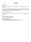
R A M P TEST P R O G R A M
3.2.1
Operation
The installation of the test procedures in the Ramp test set is based on a set of successive software
modules, that control the sequences developed in paragraph 3.1.
The execution of the tests are dependant of acknowledgement (approval), continue, interrupt or re-start
buttons. These buttons may be physically installed in front of the equipment or touch-screen operation.
3.2.2
Modules
Each module controls a succession of displays and waiting periods for any order given by the buttons:
START
display procedure name,
test contents
YES
NEXT
buttons
NEXT
YES
display settings
to enter
data in XPDR, fixed data, data ADLP
DONE
button
start or continue
procedure
modify data settings
modify
settings ?
YES
end
display PASS / FAIL
SHOW RESULTS ?
YES
NO
NO
buttons
REPEAT
STOP
display
results ?
display
NEXT
buttons
EXIT MODULE
Figure 2 : module for one procedure / basic schematics
30
Transponders Test Benches Requirements
•
display the procedure name and tests contents, wait for approval or stop or next procedure;
•
display the settings: the data to enter in the transponder via its control box (e.g. the code) or, if
applicable, to the external equipment linked to it (ADLP, ...), wait for execution order;
•
start of the procedure, stops whenever a new setting has to be applied during the procedure (e.g.
change of code), wait for continue order;
•
stops at end of testing, display of the information “ PASSED “ or “ FAILED “, wait for order display result
or go to the next procedure;
•
if result display button has been “pushed”, the successive results are presented in the form
corresponding to the measurement :
a data: e.g. Pulse Width = 455 ns (mean of 100 replies, 14 pulses) the tolerances is 350 >> 550 ns
a X/Y diagram : e.g. reply % vs. P3 width
with the tolerance areas in gray
a list of reply messages e.g. DF11, CA = 7, AA = 808080, II = 0
with the text : correct / wrong
after which the system switches over to another module.
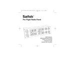
3.2.3
Trial modules
A trial is a planned sequence of procedures defined by the above modules; see the figure 3 :
START
enter date, XPDR n°,
aircraft registration, ...
keyboard
entry
DONE
start first procedure
execution of the module
(see module description )
NEXT
next / repeat
REPEAT
STOP
buttons
?
print ? exit data ?
PRINT
EXIT DATA
buttons
print , exit data
END TRIAL
Figure 3 : 1 module for 1 trial ( a series of procedures ) / basic schematics
Transponders Test Benches Requirements
31
A planned sequence is a list established depending on the user needs (planned maintenance, repair,
research, ...)
3.2.4
Fast trials
In order to speed up the trial, one can adopt a succession of test sequences, each sequence being
arranged in such a way that the same settings are used for all the tests contained, and no interrupt
messages appears during or between tests (like “ modify settings ? “ or “ display results ” or “ exit data ?“);
all data are stored in memory and printed at the end if wanted.
The only interruption in the trial is then the necessary change of settings between two sequences; see the
following figure :
START
enter date, XPDR n°
aircraft registration, ...
keyboard
entry
DONE
start group of
procedure
display group
settings to enter
data in XPDR, fixed dat, data in ADLP
DONE
button
PRINT
EXIT DATA
execution of all the test
modules of the group
NO
last
group ?
YES
print ? exit data ?
buttons
print, exit data .
END TRIAL
Figure 4 : fast trial
32
(planified group of test procedures) / basic schematics
Transponders Test Benches Requirements
Example of succession of sequences :
- Set code to A 7377 + SPI
sequence P51 - P57 - P75 -P52 ;
- change code to 4000
P52 again ;
- change code to 0400
P52 again ;
- change code to 1642 and switch off the altimeter
sequence P53 - P58 - P62 - P66 - P71 - P72 - P77 - P85 - P86 - P87 ;
- print the result.
3.2.5
Other possibilities
The system built for the ramp test set needs some flexibility; one must be able to modify the
characteristics of the tests. It is an obligation to allow
- the evolution of maintenance rules, these being adapted to the ATC SSR problems and to manufacturing
changes,
- the research and developments of administrations and airliner maintenance services,
- the easy building of the laboratory test set variant.
This implies the “availability” of the modules: one must be able to access the measurement parameters
(number of iterations, succession of Mode S formats, etc...), with the sole limitations that only authorized
technicians may control these elements and that in any case, the default values are set back for the usual
operator. Unauthorized values (too large, ..., impossible message subfield, ...) for the test parameters are
announced to the operator and the system wait for new entry.
3.2.6
Results management
3.2.6.1
Memory
All results are automatically written in memory; it contains the date, the transponder under test references
(serial number, aircraft registration, Mode S address), each successive test protocol (number, name), the
conditions of the test (settings), the resulting data (whatever the form) even if no display was asked by the
operator during the test.
3.2.6.2
Result transfer
The contents of the memory must be transferable by any actual means (floppy disk or equivalent, GPIB
bus, RS232, ...) to another computer base or local network. Printer output is required.
3.2.7
Autotest
The system must contain an autotest device, that is automatically launched before any operation starts.
This autotest verifies the input and output of the system and can control the exactness of the
measurements through a reference transponder.
It must be possible to introduce the distance ramp tool -- aircraft antenna before starting the tests, in order
to the apply the corresponding time delay correction.
Transponders Test Benches Requirements
33
3.3
TECHNICAL D A T A
The equipment must be able to generate all the tests described in the test lists above and therefore must
have the following capacities:
3.3.1
3.3.2
3.3.3
3.4
Output / Uplink characteristics
•
frequency : 1020 - 1040 MHz, in steps of 0.2 MHz
•
pulse : minimum width 250 ns, in steps of max 25 ns,
with intervals of 200 ns between one pulse decay and the next pulse rise
pulse rise and decay times respecting ICAO Annex 10
DPSK modulation for uplink P6 pulses (idem)
•
pulse sequences : all Mode A, C, Intermode A, C,S
that is, all combinations of two following P1, P2, P3, P4 trains;
Mode S UF / DF 00, 04, 05, 11, 16, 17, 20, 21, 24 with any field and subfield contents;
time delays up to 30 sec (use in lockout tests if these test are added)
•
repetition rate : PRF 1 to 100 Hz in Mode S, to 2000 Hz in the other Modes
•
power : for measurements at 2 to 25 (or 15 ) meters: up to 37 or 44 dBm ( 5 or 25 W)
(at output of antenna), in steps of 0.5 dB
difference between channels : up to . . . . .
•
physical output : 10 W maximum to antenna through connecting cable ( connector “N” )
•
antenna : directional, on a tripod.
Input / Downlink characteristics
•
frequency : 1070 - 1110 MHz, resolution 0.01MHz
•
pulse :
minimum width 200 ns, resolution 25 ns (or shorter)
with intervals of 200 ns between one pulse decay and the next pulse rise pulse rise
and decay times measurable
•
power :
up to 0.1W (17 dBm) at input to antenna, with a resolution of 0.5 dB.
Display
•
active matrix for confortable external natural light
•
9 inch screen 800 x 600 pixels
•
either 20 lines of text or diagram X/Y
•
dialog windows with on-screen buttons data result presentation.
COMBINED BENCH
As presented in § 1.4 and displayed in Figure 1 (see page 4), it would be recommended to foresee the
physical capacity of inserting the ramp tool in the maintenance laboratory equipment, that is,
- to give the possibility to insert the ramp tool as a rack subpart of the lab tool,
- with the necessary connections for synchronisation
(The lab tool has two RF channels with independant clocks and pulse generation but their starts must be
synchronisable, for diversity tests and similar measurements).
3.5
TESTING ENVIRONMENT
The equipment will be used essentially on external.
- Power input :
90 to 240 V , 45 - 440 Hz
- Temperature, humidity and other similar characteristics : as usual for this type of equipment.
34
Transponders Test Benches Requirements
4
LABORATORY TEST BENCH
4.1
PROCEDURE DESCRIPTION
Legend
1 - MS = Eurocae MOPS ED-73A for SSR transponders : performance specifications;
2 - MT =
“
“
“
“
“
: test procedures data;
3 - Mean: in the 3 paragraphs 4.1, 4.2 & 4.3, all values are computed as the mean of
100 replies (identical [ interrogation -- reply] sequences);
4 - Time spacing are counted from the pulse front edge at half amplitude.
5 - As the transponder is cable connected to the bench test set, the codes used in Mode A may be set
to their maximum load, that is, 7777 (this could not be done in the air with the Ramp test set, as this
code is used for emergency! ).
Note about the Test Sequence
Procedures P 58 & 77 should be executed before the other Receiver capability tests ( 58 before 59 to
67, and 77 before 78 to 87 ) as they measure the different MTLs whose values are used in other tests.
So, it is recommended to follow simply the numerical order ( 51 to 67, 71 to 87) when usually testing the
Electric Parameters.
Installations
This simplest installation of Figure 5 hereunder is used for all tests, except when otherwise stated.
Airborne
data
simulator
slave
RF unit
main
RF unit
XPDR
PC and
display
Figure 5
Transponders Test Benches Requirements
35
Test procedures P 51 and P71 use the following installation :
Airborne
data
simulator
slave
RF unit
main
RF unit
stub tuner
variable
air line
slotted line
XPDR
PC and
display
minimum lenght of cable or attenuator
Figure 6
Test procedures P1, P56 and P74 use the following installation :
Airborne
data
simulator
detected
video
slave
RF unit
main
RF unit
oscilloscope
sync
XPDR
PC and
display
Figure 7
36
Transponders Test Benches Requirements
Test procedures P 65, P79 and P83 use the following installation :
Airborne
data
simulator
detected
video
slave
RF unit
XPDR
main
RF unit
oscilloscope
sync
PC and
display
Figure 8
Test procedures P 76 uses the following installation :
Airborne
data
simulator
top
slave
RF unit
bottom
main
RF unit
PC and
display
XPDR
XPDR
take care that the delays & loss
in cables are identical
Figure 9
Transponders Test Benches Requirements
37
Test procedures P 7 uses the following installation :
Airborne
data
simulator
slave
RF unit
main
RF unit
PC and
display
XPDR
sync
Control
box
Figure 10
Test procedures P 6, P15, P16, P18, P21 to P28 use the following installation :
Airborne
data
simulator
slave
RF unit
main
RF unit
PC and
display
XPDR
if XPDR
& ADLP
are
separated
ARINC 718
Williamsburg
Williamsburg
ADLP
XPDR
+
ADLP
if XPDR
& ADLP
are
in one unit
Figure 11
38
Transponders Test Benches Requirements
4.1.1
Mode A&C Procedures
Procedure
a
P 51
Verification
Reply Frequency.
b
Performance specifications
MS 3.3.1 -
c
MT 5.4.2.1.
Installation & fixed settings
Connect the equipment’s as on figure 6;
interrogator at nominal setting; level at XPDR input : -50 dBm; Mode A ; XPDR code : A 7777 .
d
Test progress
To measure the frequency, adjust the line stretcher for maximum transmitter frequency shift above or
below 1090 MHz .
e
Measurement & display
Record the frequency (mean value of all pulses).
Procedure
a
P 52
Verification
Mean Output Power, Pulse Amplitude Variation, Mean Pulse Width, Pulse Positions,
Mode A Pulse Decoding.
b
Performance specifications
MS 3.3.3, 3.5.1 to 6 - MT 5.4.2.2 , 5.4.3.1 .
c
Fixed settings
Interrogator at nominal setting; level at XPDR input : -50 dBm; Mode A.
d
Test progress
100 [ interrogation
reply ] sequences with XPDR set to code A 7777 & PRF 200 Hz;
repeated with successively code A 7777 & PRF 1000 Hz; code A 7777 & PRF 1200 Hz;
code A 4000 & PRF 500 Hz; code A 0400 & PRF 500 Hz.
e
Measurement & display
Reply code displayed;
for each code and power combination:
power :
mean value of all pulses / mean value of lowest pulse
maximum variation between all pulse in a reply (min-max);
position of ALL pulses (vs. F1 + n x 1.45 µs ) : mean value of each pulse
and the maximum offset (that is, the offset of the “worst” pulse);
pulse width: mean value of all pulses.
Transponders Test Benches Requirements
39
Procedure
a
P 53
Verification
Delay Time, Delay Time Jitter, Delay Time Difference Mode A vs. C, Code C .
...
idem Ramp Test set (see page 17).
Procedure
a
P 54
Verification
Delay Time vs. Input Level .
b
Performance specifications
MS 3.7.1 - MT 5.4.3.3 .
c
Fixed settings
Interrogator at nominal setting; PRF 500 Hz; Mode AXPDR code set to A 7777;
( repetition under Mode C is not necessary);
XPDR altimeter switched out.
d
Test progress
100 [ interrogation
e
reply ] sequences.
Measurement & display
Diagram : delay time vs. input level; being different from one transponder to another, the form of the curve
may be interpreted as the “ signature” of the transponder.
Procedure
a
P 55
Verification
Unsollicited replies.
b
Performance specifications
MS 3.1.3 - MT 5.4.8 .
c
Fixed settings
No interrogations;
for Mode S transponders, inhibit the squitter generation with one of the external equipment's switch.
d
Test progress
Wait 30 sec.
e
Measurement & display
Count the number of (unsollicited) replies Mode A; should not be greater than 5 per sec;
idem Mode C; same limit;
idem Mode S; should not be greater than 1 per 10 sec.
40
Transponders Test Benches Requirements
Procedure
a
P 56
Verification
Pulse Rise & Decay Times.
b
Performance specifications
MS 3.5.4 - MT 5.4.3.1 .
c
Installation & Fixed settings
Connect the equipment’s as on figure 7;
interrogator at nominal setting; PRF 500 Hz; level at XPDR input : -50 dBm; Mode A.
d
Test progress
continuous [ interrogation
reply ] sequences (time to examine the screen);
XPDR code : successively A 7777, A 0400, A 1010, A 0010.
e
Measurement & display
determine rise and decay times with screen markers,
for the various combinations of pulses, give the variation if there is one.
Procedure
a
P 57
Verification
Reply Rate vs. PRF.
b
Performance specifications
MS 3.4.1 - MT 5.4.2.5 .
c
Installation & Fixed settings
Interrogator at nominal setting; level at XPDR input : -50 dBm;
XPDR code A7777 + SPI.
d
Test progress
PRF ; 100 interrogations per sec during one sec, followed by 5 sec rest,
Then increase the PRF in steps of 50 Hz up to 2000 Hz, with 5 sec rest between each step.
e
Measurement & display
Diagram : reply % vs. PRF.
Procedure
a
P 58
Verification
Modes A & C Sensitivity (MTL).
...
idem Ramp Test set (see page 18) but with levels at XPDR input running from -21 to -80 dBm.
Transponders Test Benches Requirements
41
Procedure
a
P 59
Verification
Dead Time.
b
Performance specifications
MS 3.10.3 - MT 5.4.4.1 .
c
Installation & Fixed settings
Interrogator at nominal setting; PRF 450 Hz;
XPDR code A 1642 .
d
Test progress
100 [ interrogation
reply ] sequences as follows:
Mode A ( level at XPDR input : -21dBm)
followed by a variable delay
followed by a Mode A interrogation ( level MTL + 3 dB);
the delay varies from 50 to 125 µs per 1µs steps.
e
Measurement & display
Diagram : reply % vs. delay; the dead time = the value when reply rate crosses 90 %.
Procedure
a
P 60
Verification
Suppression Time.
b
Performance specifications
MS 3.8 - MT 5.4.4.1 .
c
Fixed settings
Interrogator at nominal setting; PRF 450 Hz;
XPDR code : A 1642 .
d
Test progress
100 [ interrogation
reply ] sequences as follows:
P1 - P2 (δ t 2 µs , same level) followed by a variable delay followed by a Mode A interrogation
delay : from 15 to 55 µs per 1µs steps;
test done at: -21, -50, -65 dBm & MTL + 3 dBm.
e
Measurement & display
Diagram : reply % vs. delay; the suppression time = the value when reply rate crosses 10 %;
shown for each level.
42
Transponders Test Benches Requirements
Procedure
a
P 61
Verification
Receiving Frequency Acceptance.
b
Performance specifications
MS 3.2.2 - MT 5.4.1.2 .
c
Fixed settings
Interrogator at nominal setting except the frequency; PRF 450 Hz
XPDR code : A 1642 .
d
Test progress
100 [ interrogation
reply ] sequences for levels at input XPDR from –60 dBm >> −80 dBm
repeated for 1029 >> 1031 MHz in 0.1 MHz steps.
e
Measurement & display
The program extracts each input power level where the reply % crosses the value 90%;
Diagram : MTL vs. input frequency.
Procedure
a
P 62
Verification
Sidelobe Suppression vs. P1 / P2 Level Ratio.
...
idem Ramp Test set (see page 18) but with levels at XPDR input running from -21 to MTL + 3dB.
Procedure
a
P 63 + 82
Verification
Sidelobe Suppression vs. P1 >> P2 Spacing.
b
Performance specifications
MS 3.8 - MT 5.4.4 .
c
Fixed settings
Interrogator at nominal setting; PRF 450 Hz; P2 at nominal width;
XPDR code : A 1642, altimeter at zero;
d
Test progress
P2/ P1 ratio varying from -12 >> + 3 dB, per 1 dB steps
100 [ interrogation
reply ] sequences for each step
repeated for 3 levels at XPDR input : -21, -50 dBm & MTL + 3 dB.
Mode A, C & Intermode A, C.
e
Measurement & display
For each of the 4 Modes and the 3 input power levels :
a diagram : reply % vs. P1 >> P2 spacing, tolerance areas shown.
Transponders Test Benches Requirements
43
Procedure
a
P 64
Verification
Sidelobe Suppression vs. P2 Width.
b
Performance specifications
MS 3.8.2 - MT 5.4.4.1 .
c
Fixed settings
Interrogator at nominal setting; PRF 450 Hz; level P2 = level P1;
XPDR code : A 1642, altimeter at zero.
d
Test progress
Width P2 varying from 0.20 µs >> 1.20 µs, per 25 ns steps
100 [ interrogation
reply ] sequences for each step
repeated for the level at XPDR input : -21, -50 dBm & MTL + 3 dB .
e
Measurement & display
Diagram : reply % vs. P2 width, tolerance areas shown (for the 3 input power levels).
Procedure
a
P 65 + 83
Verification
Interference.
b
Performance specifications
MS 3.12 - MT 5.4.7 .
c
Installation & fixed settings
Connect the equipment’s as on figure 8;
master interrogator at nominal settings for both Mode A/C and Mode S,
slave interrogator synchronized in PRF only ;
the other parameters are defined hereunder.
d
Test progress
Pulse(s) in variable positions & levels is/are added by the slave unit to the master interrogation,
following the procedure described in MT 5.4.7.2 ( steps 1 to 5).
e
Measurement & display
Diagram : reply % vs. interference pulses relative positions & levels.
Procedure
a
P 66
Verification
Mode A & C Acceptance vs. P1 >> P3 Spacing.
...
idem Ramp Test set (see page 19)
but more levels at XPDR input: -21dBm, -50 dBm, MTL + 10 dB, MTL + 3dB.
44
Transponders Test Benches Requirements
Procedure
a
P 67
Verification
Mode A & C Acceptance vs. P1 & P3 Width.
b
Performance specifications
MS 3.9.4 - MT 5.4.5.2 .
c
Fixed settings
Interrogator at nominal except width P1 & P3; no P2; PRF 450 Hz; level at XPDR input: MTL +10 dB;
XPDR code : A 1642 .
d
Test progress
P1 & P3 width varying from 0.20 >> 1.20 µs, per 25 ns steps
100 [ interrogation
e
Measurement & display
Diagram : reply % vs. P1 & P3 width (both Modes A & C), tolerance areas shown.
4.1.2
Mode S electric and Intermode A&C Procedures
Procedure
a
reply ] sequences for each step.
P 71
Verification
Reply Frequency.
b
Performance specifications
MS 3.3.1 - MT 5.4.2.1 .
c
Installation & Fixed settings
Connect the equipment’s as on figure 6;
interrogator at nominal setting; PRF 50 Hz; level at XPDR input : -50 dBm; Intermode A ;
XPDR code : A 7777 .
d
Test progress
To measure the frequency, adjust the line stretcher for maximum transmitter frequency shift above or
below 1090 MHz.
e
Measurement & display
Record the frequency (mean value of all pulses).
Procedure
a
P 72
Verification
Mean Output Power, Pulse Amplitude Variation, Mean Pulse Positions, Mean Pulse Width.
...
idem Ramp Test set (see page 20).
Transponders Test Benches Requirements
45
Procedure
a
P 73
Verification
Delay time, Delay Time Jitter.
b
Performance specifications
MS 3.7.2 - MT 5.4.3.3
c
Fixed settings
Interrogator at nominal setting; PRF 50 Hz; level at XPDR input : -50 dBm.
d
Test progress
100 [ interrogation
e
reply ] sequences.
Measurement & display
Delay time (P6 / Sy Ph Rev to first preamble pulse) : mean value and σ .
Procedure
a
P 74
Verification
Pulse Rise & Decay Times in (Inter)Mode S.
b
Performance specifications
MS 3.6.5 - MT 5.4.3.2 .
c
Installation & fixed settings
Connect the equipment’s as on figure 7.
d
Test progress
Continuous [ interrogation
reply ] sequences (time to examine the screen);
XPDR code : A 1642 .
e
Measurement & display
Observe the rise and decay times with screen markers, of the various pulses
and give the variation if there is one.
Remark : this test requires the same installation as test 56, so both should be executed sequentially.
Procedure
a
P 75
Verification
Mixed Reply Rate Capability.
...
46
idem Ramp Test set (see page 20).
Transponders Test Benches Requirements
Procedure
a
P 76
Verification
Diversity Isolation.
b
Performance specifications
MS 3.16 - MT 5.4.11 .
c
Installation & fixed settings
Connect the equipment as on figure 9;
master interrogator at nominal setting;
slave unit synchronized with a controlled difference in start time and power level;
used : Mode A, Mode C, Intermode A + S, Intermode C only, UF04 ( & UF 21 if applicable).
d1
Test progress 1
Single channel interrogations at 3 different levels :
MTL + 3 dB / -50 dBm ( only Mode C & UF04 ) / -21 dBm ( id. )
applied first on Bottom channel, then onTop channel.
e1
Measurement & display 1
record in each case, output power, delay time, reply percentage
compare theses values between each channel
the power transmitted on the “ unwanted “ channel must beat least 20 dB lower.
d2
Test progress 2
Dual channel interrogations at 4 level combinations :
1 -
Top @ MTL,
Bottom @ MTL + 4 dB :
2 -
Top @ MTL + 4 dB,
Bottom @ MTL
3 -
Top @ MTL + 4 dB,
Bottom @ - 50 dBm
4 -
Top @ - 50 dBm,
Bottom @ MTL + 4 dB
vary the ∆time between Top & Bottom interrogations from – 600 ns to + 600 ns.
e2
Measurement & display 2
Diagram : reply % at each channel output vs. ∆ time between interrogations;
tolerance areas shown.
Procedure
a
P 77
Verification
Intermode A & C and Mode S Sensitivity (MTL).
...
idem Ramp Test set (see page 21) but with levels at XPDR input running from -21 to -80 dBm.
Transponders Test Benches Requirements
47
Procedure
a
P 78
Verification
Dead Time.
b
Performance specifications
MS 3.10.3 - MT 5.4.6.2 .
c
Fixed settings
Interrogator at nominal setting; PRF 50 Hz.
d
Test progress
100 [ interrogation
reply ] sequences as follows:
Mode S ( level at XPDR input : -21dBm) / wait for the reply end /
followed by a variable delay followed by a Mode S interrogation at level MTL + 3 dB;
the delay varies from 50 to 125 µs per 1µs steps.
e
Measurement & display
Diagram : reply % vs. delay; the dead time = the value where reply rate crosses 90 %.
Procedure
a
P 79
Verification
Suppression Time.
b
Performance specifications
MS 3.8.3 - MT 5.4.4.3 .
c
Fixed settings
Connect the equipment’s as on figure 8;
Interrogator at nominal setting; PRF 50 Hz.
d
Test progress
100 [ interrogation
reply ] sequences as follows:
P1 - P2 (∆ t = 2 µs , same level ) followed by a variable delay followed by a Mode A interrogation
delay : from 15 to 55 µs per 1µs steps;
test done at: -21, -50, -65 dBm & MTL + 3 dBm.
e
Measurement & display
Diagram : reply % vs. delay; the suppression time = the value where reply rate crosses 10 %;
shown for each level.
48
Transponders Test Benches Requirements
Procedure
a
P 80
Verification
Receiving Frequency Acceptance, Bandwidth.
b
Performance specifications
MS 3.2.2 & 3 - MT 5.4.1.2 .
c
Fixed settings
Interrogator at nominal setting except the frequency; PRF 50 Hz.
d
Test progress
1 - 100 [ interrogation
reply ] sequences for levels at input XPDR from -60 >> −80 dBm
repeated for 1029 >> 1031 MHz in 0.1 MHz steps;
2 - 100 [ interrogation
reply ] sequences for levels at input XPDR MTL + 60 dB
repeated for 1000 >> 1020 MHz & 1040 >> 1060 MHz in 0.5 MHz steps.
e
Measurement & display
Diagram : MTL vs. input frequency;
in part 2 , the program extracts the power level where the reply % crosses the value 90.
Procedure
a
P 81
Verification
Sidelobe Suppression vs. P5 / P6 Level Ratio.
b
Performance specifications
MS 3.8.3 - MT 5.4.4.3 .
c
Fixed settings
Interrogator at nominal setting; UF04.
d
Test progress
with a P2 at nominal position & width, P5/ P6 ratio varying from -15 dB >> + 6 dB, per 1 dB steps
100 [ interrogation a reply ] sequences for each step
repeated for the level at XPDR input : -21 dBm, -50 dBm & MTL + 3 dB.
e
Measurement & display
Diagram : reply % vs. P5/P6 ratio, tolerance areas shown (for the three input power levels).
Procedure
P 82
see page 43, tests P63 + 82.
Procedure
P 83
see page 44, tests P65 + 83.
Transponders Test Benches Requirements
49
Procedure
a
P 84
Verification
Intermode A % C Acceptance vs. P1 >>P3 Spacing.
b
Performance specifications
MS 3.9.3 - MT 5.4.5.2.
c
Fixed settings
Interrogator at nominal setting ; no P2; P3 >> P4 spacing nominal;
( XPDR code : A 1642.
d
Test progress
Level at XPDR input: -21, -40 & -60 dBm
P1 >> P3 spacing varying from 6.5 >> 9.5 µs and 19.5 >> 22.5 µs, per 25 ns steps
100 [ interrogation
e
reply ] sequences for each step.
Measurement & display
Diagram : reply % vs. P1 >> P3 spacing, tolerance areas shown
for both Intermode A ( 6 >> 10 µs ) and Intermode C ( 19 >>23 µs )..
Procedure
a
P 85
Verification
Intermode A & C Acceptance vs. P4 Width.
… idem Ramp Test set (see page 21).
Procedure
a
P 86
Verification
Intermode A & C Acceptance vs. P3 >> P4 Spacing.
… idem Ramp Test set (see page 22).
Procedure
a
P 87
Verification
Mode S Acceptance vs. P2 >> P6 (Sync. Phase Reversal) Spacing.
… idem Ramp Test set (see page 22).
50
Transponders Test Benches Requirements
4.1.3
Mode S Protocol Procedures
Procedure
a
P 1
Verification
Error Protection.
b
Performance specifications
MS 3.20.2.1 - MT 5.5.8.1 / protocol procedure n° 1.
c
Installation & fixed settings
Connect the equipment’s as on figure 7;
interrogator at nominal setting; level at XPDR input : -50 dBm.
d
Test progress and Control
1 – Downlink coding for PI fields
If the XPDR has a static CA: set the address (manually on the back connector) as follows :
if
CA = 0,
AA
set to [ 03 13 D4 ]hex
CA = 4,
AA
set to [ 03 2B E2 ]hex
CA = 5,
AA
set to [ FC DF EB ]hex
CA = 6,
AA
set to [ 03 37 F9 ]hex
CA = 7,
AA
set to [ FC C3 F0 ]hex.
Send an Intermode A/S and verify that in the reply PI is all zeros ( detected video on the oscilloscope).
If the XPDR is of dynamic CA type, adopt the procedure to vary the CA as necessary with
simultaneously changing the address as above, and verify similarly.
2 – Downlink coding for AP fields
Interrogate the XPDR to get DF05 and DF21 replies that are observed on the oscilloscope;
set the address (manually on the back connector) to
Procedure
a
AA = [ 20 78 CE ]hex
>>
DF05 should contain all zeros,
[ 75 2D 9B ]hex
>>
DF05 should contain [ 55 55 55]hex ,
[ 0B 15 4F ]hex
>>
DF21 should contain all zeros,
[ 75 2D 9B ]hex
>>
DF05 should contain [ 55 55 55] hex.
P 2
Verification
Interrogation Acceptance.
...
idem Ramp Test set (see page 24).
(There are no P3, P8 & P14; see table 5 page 14 ).
Transponders Test Benches Requirements
51
Procedure
a
P 4
Verification
Non-selective All-call Lockout.
b
Performance specifications
MS 3.20.2.4 - MT 5.5.8.4 / protocol procedure n° 4 - Ref.11 "Mode-S … SI-code validation".
c
Installation, preparation & fixed settings
Connect the XPDR to the Bench test, as on figure 5;
interrogator at nominal setting; in Modes A/C & Intermodes: no P2; P3 >> P4 spacing nominal;
Mode S UF04, 05 &11 ; and UF20 & 21 if XPDR is Mark 4 type (see the dual asterisks** ).
Two interrogations sequences are prepared:
- sequence 4P, the positive tests: at well defined times, they test the XPDR's no reply when it must be
locked & the replies when lockout must be finished;
- sequence 4N, the negative tests: when the lockout has not to be engaged.
S equence of interrogations 4 P – Positive tests
a at t = 0 send [ UF04 ][PC = 1 ][ RR=0 ][ DI=1][ SD : IIS=1, 00000, LOS=0, 000000 ][ AP]
b at t = 0.02 s
send Intermode A/S
No Reply expected
c at t = 0.04 s
send Intermode C/ S
No Reply expected
d at t = 0.06 s
send ModeS ( UF11, IC = 0, CL=0, PR = 0)
No Reply expected
e at t = 16.90 s
repeat sequences b, c & d
f at t = 19.10 s
send Intermode A/S All-Call
lockout is finished
g at t = 19.12 s
send Mode A, Mode C & Mode S
lockout is finished
h at t = 19.14 s
send ModeS ( UF11, IC = 0, CL=0, PR = 0)
lockout is finished
i
send [ UF05 ][ PC =1 ][ same data . . . ]
at t = 21.00 s
j at t = 21.02 s
repeat sequences b, c & d
k at t = 26.00 s
send [ UF20 ][ PC = 1 ][ same data . . . ]
(**)
l
repeat sequences b, c & d
(**)
m at t = 31.00 s
send [ UF21 ][ PC = 1 ][ same data . . . ]
(**)
n at t = 31.02 s
repeat sequences b, c & d
(**)
o at t = 41.90 s
repeat sequences b, c & d
(**)
p at t = 46.90 s
repeat sequences b, c & d
(**)
q at t = 50.10 s
repeat sequences f, g & h.
(**)
at t = 26.02 s
S equence of interrogations 4N – Negative tests
The non-lockout is verified against PC values, broadcast interrogations, addresss,and II/SI-codes;
send a first [ UFxx ][PC = .. ][ RR=0 ][ DI=1][ SD = IIS .. , 00000, LOS, 000000 ][ AP = .. ],
UF04, 05, 20 & 21 (**), PC = 0, 2 to 7,
IIS = 0, LOS = 1
UF04, 05, 20 & 21 (**), PC = 0 to 7,
UF04, 05, 20 & 21 (**), PC = 1,
IIS =1, LOS = 0, Address = [ FFFFFF ]hex
IIS = 0, LOS = 1, Address is not the XPDR's one
then verify NO LOCKOUT is engaged by sending sequentially the Intermode A/S & C/S and
UF11, with PR = 0,
II =1 to 15
etc…
see ref.11 and MT 5.5.8.4 for the details.
d
Test progress and Control
Start the sequence 4P; the program displays line after line each uplink messages and the related reply or
no reply, both with time marks; an "OK" symbol is added at line end, replaced by the reply contents if
faulty ( e.g. if no reply is expected) or "sorry, No Reply" when so where one reply is expected;
start the sequence 4N; same verification.
52
Transponders Test Benches Requirements
Procedure
a
P 5
Verification
Multisite Selective Lockout.
b
Performance specifications
MS 3.20.2.5, 3.21.2.1 - MT 5.5.8.5 / protocol procedure n° 5 - Ref.11 "Mode-S … SI-code validation".
c
Installation, preparation & fixed settings
As in procedure P 4, but the lockout is now selective : that is, the XPDR does not reply to All-call's
coming from the interrogator that initiated the lockout; in the interrogations sequences hereunder,
message are sent at well defined times to test the XPDR's non-reply to the correct UF11 when it must be
locked & positive replies either when lockout must be finished, or when interrogated by another
interrogator, or when the lockout has not to be engaged; restarts of lockouts is also tested.
x = 1 to 15; y = 1 to 63; to gain time, UF04 and 05 are mixed, as well as UF20 and 21 (see the sequences).
S equence of interrogat ions 5 / 1 – Timer duration and insensivity to non-valid signals tests
a) sequences for IIS
at t = 0 send
UF04 PC=0 RR=0
DI =1
SD : IIS=x , 00000 , LOS=1, 000000
AP
at t = 0.02 s
send UF11 with II = x
No Reply expected
at t = 0.04 to 9.90 s
send UF11 with II not = x
No Reply expected
at t = 0.3 s
interlace : send UF05 with IC = x+1
at t = 10.0 to.. s
send UF05 with II = x but with all 6x2 other DI / LOS incorrect combinations
at t = 13.3 to.. s
send UF04 with II = x but with all 8x2 other DI / LSS combinations
at various t
send Mode A/C and Intermode all-call interrog.
Reply expected
at t = 16.9 s
send UF11 with II = x
No Reply expected
at t = 19.1 s
send UF11 with II = x
Reply expected
repeat the sequence inverting simultaneously UF04 <-> 05, DI =1 <-> 7.
b) sequence for SIS
at t = 0 send
UF05 PC=0 RR=0
DI =3
SD : SIS=y , LSS=1, 000000000
AP
at t = 0.02 s
send UF11 with SI = y
No Reply expected
at t = 0.04 to 9.90 s
send UF11 with SI not = y
No Reply expected
at t = 0.3 s
interlace : send UF04 with ISI = y+1
at t = 10.0 to.. s
send UF04 with SI = y but with all 8x2 other DI / LOS combinations
at t = 13.3 to .. s
send UF04 with SI = y but with all 6x2 other DI / LSS incorect combinations
at various t
send Mode A/C and Intermode all-call interrog.
Reply expected
at t = 16.9 s
send UF11 with SI = y
No Reply expected
at t = 19.1 s
send UF11 with SI = y
Reply expected
Transponders Test Benches Requirements
53
S equence of interrogations 5 / 2 – Restart capability and Sensivity to vali d signals tests
a) sequences for IIS
at t = 0 send
at t = 0.02 s
UF04 PC=0 RR=0
DI =1
SD : IIS=x , 00000 , LOS=1, 000000
send UF11 with II = x
AP
No Reply expected
at t = 0.04 + n x 0.3s interlace with UF04 with II not = x
at t = 4.5 s
restart : send UF05 with II = x
at various t
send Mode A/C and Intermode all-call interrog.
Reply expected
at t = 21.4 s
send UF11 with II = x
No Reply expected
at t = 23.6 s
send UF11 with II = x
Reply expected
repeat the sequence inverting simultaneously UF04 <-> 05, DI =1 <-> 7.
b) sequence for SIS
at t = 0 send
at t = 0.02 s
UF05 PC=0 RR=0
DI =3
SD : SIS=y , LSS=1, 000000000
send UF11 with SI = y
AP
No Reply expected
at t = 0.04 + n x 0.3s interlace with UF05 with SI not = y
at t = 4.5 s
restart : send UF04 with SI = y
at various t
send Mode A/C and Intermode all-call interrog.
Reply expected
at t = 21.4 s
send UF11 with SI = y
No Reply expected
at t = 23.6 s
send UF11 with SI = y
Reply expected
S equence of interrogatio ns 5 / 3 – Restart capability and Sensivity to valid signals tests
For XPDRs level 2 & above only
a) sequences for IIS
at t = 0 send
at t = 0.02 s
UF20 PC=0 RR=0
DI =1
SD : IIS=x , 00000 , LOS=1, 000000
send UF11 with II = x
MA
AP
No Reply expected
at t = 0.04 + n x 0.3s interlace with UF04 with IIS not = x
at t = 4.5 s
restart with
UF21 PC=0 RR=0
DI =1
SD : IIS=x , 00000 , LOS=1, 000000
MA
at various t
send Mode A/C and Intermode all-call interrog.
Reply expected
at t = 21.4s
send UF11 with II = x
No Reply expected
at t = 23.6 s
send UF11 with II = x
Reply expected.
AP
repeat the sequence inverting simultaneously UF20 <-> 21, DI =1 <-> 7.
b) sequence for SIS
at t = 0 send
at t = 0.02 s
UF20 PC=0 RR=0
DI =3
SD : SIS=y , LSS=1, 000000000
send UF11 with SI = y
MA
AP
No Reply expected
at t = 0.04 + n x 0.3s interlace with UF04 with SI not = y
at t = 4.5 s
restart with
54
UF21 PC=0 RR=0
DI =3
SD : SIS=y , LSS=1, 000000000
MA
at various t
send Mode A/C and Intermode all-call interrog.
Reply expected
at t = 21.4s
send UF11 with SI = y
No Reply expected
at t = 23.6 s
send UF11 with SI = y
Reply expected.
AP
Transponders Test Benches Requirements
S equence of interrogations 5 / 4 – Broadcast discrimination tests / sequence for IIS
a) For all XPDRs
at t = 0 send
UF04 PC=0 RR=0
DI =1
SD : IIS=x , 00000 , LOS=1, 000000
at t = 0.02 s
send UF11 with II = x
at t = 0.04 s
interlace with UF05 with II not = x
at t = 0.06 s
send UF11 with II = x
b) For XPDRs level 2 & above only
UF20 PC=0 RR=0
at t = 0 send
ad=FFFFFF
Reply expected
Reply expected
DI =1
SD : IIS=x , 00000 , LOS=1, 000000
at t = 0.02 s
send UF11 with II = x
at t = 0.04 s
interlace with UF21 with II not = x
at t = 0.06 s
send UF11 with II = x
MA
ad=FFFFFF
Reply expected
Reply expected
S equence of interrogations 5 / 5 – Broadcast discrimination tests / sequence for SIS
a) For all XPDRs
at t = 0 send
UF04 PC=0 RR=0
SD : SIS=y , LSS=1, 000000000
at t = 0.02 s
send UF11 with SI = y
at t = 0.03 s
interlace with UF05 with SI not = y
at t = 0.06 s
send UF11 with SI = y
b) For XPDRs level 2 & above only
UF20 PC=0 RR=0
at t = 0 send
d
DI =3
ad=FFFFFF
Reply expected
Reply expected
DI =3
SD : SIS=y , LSS=1, 000000000
at t = 0.02 s
send UF11 with SI = y
at t = 0.03 s
interlace with UF21 with SI not = y
at t = 0.06 s
send UF11 with SI = y
MA
ad=FFFFFF
Reply expected
Reply expected
Test progress and Control
Start the sequence 5/1; the program displays line after line each uplink messages and the related reply
or no-reply, both with time marks; an "OK" symbol is added at line end, replaced by the reply contents if
faulty ( e.g. if no reply is expected) or "sorry, No Reply" when so where one reply is expected;
start the other sequences; same verifications.
Transponders Test Benches Requirements
55
Procedure
a
P6
Verification
Acquisition and Extended Squitters : complete test.
b
Performance specifications
MS 3.20.2.6, 3.21.2.6, 3.21.1.12 - MT 5.4.3.2.2 & .3
ANNEX 10 (ref.1 ) § 3.1.2.8.5 & 6.
c
Interrogation
reply sequences
Unsolicited replies in Mode S - No interrogations for the squitter themselves, but interrogations are sent
both - to determine the choice of contents in the extended squitter ME field
- to interleave the squitters with other replies.
Remark : if existing, the onboard mutual suppressing system must be inhibited.
1 - XPDRs with ACQUISITION SQUITTER ONLY
the DF 11's are transmitted with the following contents:
DF11
CA
3 bits
AA
(24 bits)
address in clear
PI
parity on II = 00
300 squitters are observed, without any interrogations.
2 - XPDRs with EXTENDED SQUITTER
Connect the equipment’s as on figure 11 ; DF 17's are transmitted with the following contents:
DF17
CA
AA
(24 bits)
address in clear
ME (56 bits)
PI
broadcast message
parity on II = 00
Prepare set of data to be filled into the airborne side of the XPDR to register 0,5 as follows:
{50 AA AA AA AA AA AA}H , {50 00 00 00 00 00 00}H , {50 FF FF FF FF FF FF}H ,
{50 xx x5 55 55 55 55}H where xx x is an hex representation of code C altitude, in steps of 25 or 100 feet,
depending on the XPDR performance.
Each of these data will be sent and refreshed each sec during 300 sec, then ceased;
send an UF04 with RR=16, DI = 7 and SD = { RRS=5, ….} to generate a GICB = 0,5 into the ME field (that
register contains the airborne position);
interleave with at random UF04 as for short squitters.
Repeat the sequence successively with RRS = 6, 8, 9 or 10 è GICB = 06, 08, 09 or 0A è ME = surface
position, aircraft ident, airborne velocity or event driven message. The set of data to be filled are
described in MT 5.4.3.2.2 .
d
Control
Verify the contents of DF 11 and DF 17 , as introduced in the transponder (ME field), incl. the DR field as
given in MS 3.18 4.5 & 8;
verify the random transmission rates for the various squitters:
diagrams: Number of events vs. time between messages (in steps of 15 ms); values are the following :
DF 11 mean rate
1/s
( limits: 0.8 to 1.2 s )
DF 17 register 05
2/
( limits: 0.4 to 0.6 s )
aircraft being set “AIRBORNE”
register 06
2/s
( limits: 0.4 to 0.6 s )
for the high rate
register 06
2 / 10 s ( limits: 4.8 to 5.2 s )
for the low rate
register 08
2 / 10 s ( limits: 4.8 to 5.2 s )
if AIRBORNE or GROUND, High rate (*)
1 / 10 s ( limits: 9.6 to 10.4 s ) if GROUND, Low rate (*).
register 09
2/s
( limits: 0.4 to 0.6 s )
register 0A
2/s
( limits: 0.4 to 0.6 s )
after reply to UF04 containing RRS = 10;
verify the maximum limit of transmission;
verify that the DF17 stops 2 sec after the last data refreshing.
( * set through UF04 with corresponding RCS subfield ).
56
Transponders Test Benches Requirements
Procedure
a
P 7
Verification
Flight status and Vertical status verification.
b
Performance specifications
MS 3.18.4.12 & .38, 3.20.2.7 & .11 - MT 5.5.8.7 / protocol procedure n° 7.
c
Installation & fixed settings
Connect the equipment’s as on figure 10; the test verifies the correct FS and VS fields contents after a
jump to an alert code, a change of Mode A code, the setting of the SPI bit and a change of Flight status;
the correct bits in fields FS and VS are given in MS 3.18.4.9 .
The test does not verify long squitter DF17 contents, wherein the flight status is also transmitted.
The interrogations sequences hereunder are different depending on the XPDR level:
for level 1 XPDRs, all tests are executed using UF04 & 05 with RR = 0, and under UF00;
for the other XPDRs (**),are used the UF04, 05, 20 & 21 with RR = 0 & 16 to 31, and UF00 & 16.
S equence of interrogations 7A – Alert tests
t = 0 when the code is changed from 1642 to 7500 or 7600 or 7700
at t = 0.02 s
send UFxx ( see above)
the reply should contain the correct code & FS field
at t = 16.9 s
send UFxx ( see above)
id.
at t = 5 min
send UFxx ( see above)
id. ( alert status is permanent).
S equence of interrogations 7B – Other code bit tests
t = 0 when the code is changed from 1642 to 1643
at t = 0.02 s
send UFxx ( see above)
the reply should contain the correct code & FS field
at t = 16.95 s send UFxx ( see above)
id.
at t = 17.05 s send UFxx ( see above)
id.
at t = 18.95 s send UFxx ( see above)
the reply should be back to "normal"
at t = 19.05 s send UFxx ( see above)
the reply should be back to "normal"
at t = 5 min
the reply should be back to "normal".
send UFxx ( see above)
S equence of interrogations 7C – SPI bit tests
t = 0 when the SPI bit is added to the code
at t = 0.02 s
send UFxx ( see above)
the reply should contain the correct code & FS field
at t = 16.95 s and after : as in sequence 7B.
S equence of interrogations 7D – Flight status tests
t = 0 when the status is changed to " In flight"
at t = 0.02 s
send UFxx ( see above)
the reply should contain the correct VS & FS fields
at t = 16.95 s and after : as in sequence 7B.
d
Test progress and Control
Set Mode A code to 1642; prepare the sequence 7A; at the control box, change the code to 7500; this
starts the bench test set ( t = 0 s) by the sync link; the program verifies each reply and displays the
correct code and FS field.
Repeat the execution with alert codes 7600 and 7700.
Reset Mode A code to 1642; prepare the sequence 7B; at the control box, change the code to 1643; this
starts...
Reset Mode A code to 1642; prepare the sequence 7C; at the control box, add the SPI bit; this starts…
Reset Mode A code to 1642 and set Flight status to " Ground " ; prepare the sequence 7D; at the control
box, change to " In flight"; this starts…
Repeat the execution reversing " In flight " to " Ground " and vice-versa.
Transponders Test Benches Requirements
57
Procedure
a
P 9
Verification
Mode S Address.
...
idem Ramp Test set (see page 26).
Procedure
a
P 10
Verification
Altitude Report.
...
idem Ramp Test set (see page 26).
Procedure
a
P 11
Verification
Mode A Report.
...
idem Ramp Test set (see page 27).
Procedure
a
P 12
Verification
RI Acquisition and Maximum Speed.
...
idem Ramp Test set (see page 27).
Procedure
a
P 13
Verification
Stochastic Acquisition.
...
58
idem Ramp Test set (see page 28).
Transponders Test Benches Requirements
Procedure
a
P 15
Verification
Comm-A Interface and Information Content.
For Mark 4 and higher level transponders only.
b
Performance specifications
MS 3.4.2, 3.17.3, 3.21.1.1 & .10 - MT 5.5.8.15 / protocol procedure n° 15.
c
Interrogation
reply sequences
Connect the equipment’s as on figure 11; the avionic side output of the XPDR ( or, of the ADLP, if both
units are grouped in one box) is decoded as necessary, in the interface decoding card of the PC subunit; interrogator at nominal setting; Mode S UF20 & 21 .
Use the hereunder defined interrogations sequence 15A at the nominal 50 int/s rate, followed by the
burst interrogations sequences 15 B & C.
S equence of interrogations 15A
3080 interrogations, at the nominal 50 int/s rate, as follows:
[ UF20 or 21 ][ PC = x ][ RR = x ][ DI = 0 ][SD = random ][ MA = zz ][AP= TP address]
where UF alternately equals 20 and 21, PC varies from 1 to 7 randomly, RR from 1 to 15 randomly,
and MA uses the 1540 patterns with just two ONE's and 1540 patterns with just two ZERO's;
5 % of the XPDRs address are replaced by Broadcast address.
S equence of interrogations 15B
100 interrogations out of any part of the sequence 15A, send in burst as follows:
at t = 0.00 s
send 4 interrogations at 2500 / s
at t = 0.08 s
send 4
"
2500 / s
at t = 0.16 s
send 8
"
320 / s
at t = 0.32 s
send 8
"
320 / s
at t = 0.48 s
send 8
"
320 / s
at t = 0.64 s
send 18
"
180 / s
at t = 1.00 s
send 4
"
2500 / s
at t = 1.08 s
send 4
"
2500 / s
at t = 1.16 s
send 8
"
320 / s
at t = 1.32 s
send 8
"
320 / s
at t = 1.48 s
send 8
"
320 / s
at t = 1.64 s
send 18
"
180 / s
S equence of interrogations 15C
100 interrogations out of any part of the sequence 15A, send in burst as follows:
at t = 0.00 s
send 4 interrogations at 2500 / s
at t = 0.08 s
send 4
"
2500 / s
at t = 0.16 s
send 8
"
320 / s
at t = 0.32 s
send 8
"
320 / s
at t = 0.48 s
send 8
"
320 / s
at t = 0.64 s
send 18
"
180 / s
at t = 0.75 s
send 16
"
180 / s
Transponders Test Benches Requirements
59
d
Control
Start the sequence 15A;
the program compares and displays line after line each uplink MA messages and the related output of the
XPDR ( or of the ADLP if both units are grouped in one box), both with time marks; an "OK" symbol is
added at line end, or the differences, if not correct.
Start the sequence 15B;
for XPDRs without memory :
same comparison;
for XPDRs with memory
it controls the sequence order is strictly the same as the one sent.
Start the sequence 15C
:
( for memory type XPDRs only );
1 sec after the burst, the program controls that at least the 50 first messages are present AND no reply
has been generated that do not correspond to these messages present.
Procedure
a
P 16
Verification
Broadcast All-call Formats ( uplink).
b
Performance specifications
MS 3.21.1.11 - MT 5.5.8.16 / protocol procedure n° 16.
c
Interrogation
reply sequences
Most of the verification is executed in procedure 15 above; one must only verify that with short uplink
formats with Broadcast address, no data are transferred to the avionic interface.
Same installation as for test procedure15.
d
Control
Send UF 00, 04 and 05 interrogations with Broadcast addresses. No data should appear at interface.
Send UF11 with both XPDR address and Broadcast address. No data should appear at interface.
Procedure
a
P 17
Verification
GICB Register Extraction / decoding only.
...
60
idem Ramp Test set (see page 29).
Transponders Test Benches Requirements
Procedure
a
P 18
Verification :
Comm-B Protocol Verification
Enhanced Comm-B Protocol Verification.
b
Performance specifications
MS 3.21.12 & 13, 3.21.2.1 & .3 - MT 5.5.8.18 & 19 / protocol procedure n° 18 & 18A
+ Ref. 9 : Mode S Specific Services Manual
MS 3.21.5.1 ( for Enhanced Comm-B )
c1
Interrogation
reply sequences
Connect the equipment’s as on figure 11; the avionic side output data of the XPDR ( or, of the ADLP, if
both units are grouped in one box) is decoded as necessary, in the interface coding/decoding card of the
PC sub-unit; the interrogator is at nominal setting.
Concerning Comm-B message transfer, the XPDR can be in 7 different states, depending on the setting
of the B-register, of the T-register, the timer running state, the Interrogator identifier and the next
message waiting state; the multisite timer being set for any of the 15 interrogators possible (IIS); this
gives a total of 63 state combinations (see the table of states in the mentioned protocol procedure 18).
Besides, numerous interrogations can be sent (to the XPDR in one of the 63 states), that modify or may
not modify the transponder state and generate or do not generate a reply; 24 interrogation patterns are
possible, some of them being executed with the 16 IIS values, leading to 294 interrogation types
combinations (see the table of interrogations in the protocol procedure 18).
So, the test bench must be able to generate interrogation sequences, that first set the transponder in a
defined state, followed by one or more interrogations that extracts (or do not extract) the desired CommB. A total of 63 x 294 = 18522 different combinations are possible, but many are done successively, by
setting the XPDR in a defined state, then sending interrogations that should not change the state,
followed by those that should.
These sequences ( lines of interrogations contents and related time of sending, time window for reply
acceptance and comparison of the reply contents to the expected ones) are to be prepared and stored in
the PC part of the test bench. These interrogation / expected replies sequences are too numerous to be
listed here, they are listed in the MT / Protocol procedure 18.
c2
Enhanced Comm-B
Applicable to high level XPDRs.
Other (than above) XPDR states are existing; so, the procedure is expanded to include additional XPDR
states, more interrogations are sent with various IIS to control the reactivity of the XPDR to various II
codes, incl. timer expiration and the UM contents. Sensitive XPDR states are also added, like
Messagers being extracted, waiting for IIS or waiting Broacast message.
As above, the interrogation / expected replies sequences are too numerous to be listed here, they are
listed in the MT / Protocol procedure 18A.
d
Control
First introduce a defined well-known message in the ADLP (see Mode S Specific Services Manual for its
contents), followed by one of the prepared sequences described above. The reply / no reply as well as
the contents of the message, accompanied by the related expected situation, received is shown on the
PC display.
Transponders Test Benches Requirements
61
Procedure
a
P 19
Verification
GICB Register Extraction & Interface, incl. AIS, Flight Identification & other BDS Protocol.
b
Performance specifications
MS 3.18.4.18 & 32, 3.21.1.13 & 17 , 3.21.2.1 -
MT 5.5.8.20 / protocol procedure n° 19
+ Ref. 9 : Mode S Specific Services Manual.
c
Interrogation
reply sequences
UF 04 or 05 : [PC = 0 ] [RR = x ] [DI = 7 ] [SD = zy00 ] [ AP = XPDRs address]
DF 20 or 21 replies;
where z is the interrogator's ident (IIS subfield), e.g. = 15
x and y vary so as to request various BDS presently in us or proposed (see hereunder),
x = sum of 16 + BDS1 subfield
y = RRS subfield = BDS2 subfield.
Hence, if the desired BDS = 4,1 , BDS1 = 4 & BDS2 = , hence RR = 20 & RRS = 1 .
The list of registers proposed for the Basic and Enhanced Surveillance is
1,0 -1,7 - 2,0 - 4,0 - 4,1 - 5,0 - 6,0
Q The transponder must be linked to the corresponding interfaces (ADLP ...) that will input the
relevant information in the corresponding register ( 255 x 56 bit buffer).
d
Control
The correct contents of the replies DF 20 or 21
[DF = 20 ] [FS = 1 ] [DR = 0 ] [UM = X ] [AC = altitude =0 ] [MB = message ] [AP = XPDRs address ]
or
[DF = 21 ] [FS = 1 ] [DR = 0 ] [UM = X ] [ID = a/c code A ] [MB = message ] [AP = XPDRs address ]
with UM = IIS followed by IDS (IIS = z above and IDS = 1 = active CommB reservation).
For each of the desired register, the MB message must be converted following the contents as defined in
the Mode S Specific Service Manual.
For example, for register = 4,0 “ Aircraft Intention” , the message content is:
bit 1 to 13 selected altitude , in steps of 16 ft ( bit 1 = status, bit 2 = MSB )
bit 14 to 24 selected altitude rate, in steps of 32 ft /min ( bit 14 = status, bit 15 = MSB )
bit 25 to 35 selected magnetic course(0) / heading(1), in steps of 360/512 deg
( bit 25 = switch (0 or 1), bit 26 = status, bit 27 = sign, bit 28 = MSB)
bit 36 to 47 selected airspeed (0) / mach number (1), in steps of 0.5 Kt or Mach 0.004
( bit 36 = switch (0 or 1), bit 37 = status, bit 38 = MSB)
bit 48 to 56 status and selection bits ...
Other example, for register = 2,0 “Flight Identification", the message content is:
[BDS = 2,0 ] [charac 1] [charac 2] [charac 3] [charac 4] [charac 5] [charac 6] [charac 7] [charac 8]
the characters giving, with ICAO international alphabet n°7, the aircraft’s registration or call sign.
Conversion software have already been developed by EUROCONTROL /EEC and could be obtained from
this source. Example of the display of these converted BDS are shown in the EEC note
“ Mode-S Specific Services and Data Link Test Bench “ (see ref. 10).
More, a complete test would require to fill the MB field with successively 1128 codes containing 2 ONEs
and 1128 codes with 2 ZEROs.
62
Transponders Test Benches Requirements
Procedure
a
P 20
Verification
Capability Report.
b
Performance specifications
MS 3.18.4.18 & 32, 3.21.1.12 & 17, 3.23.1.2b
-
MT 5.5.8.21 / protocol procedure n° 20.
+ Ref. 9 : Mode S Specific Services Manual.
c
Interrogation
reply sequences
A particular case of procedure P19, with RR = 17, y = 0 and 7
d
( BDS = 1,0 and 1,7 ).
Control
Same as for test procedure P19.
Depending on the level of the transponder, it determines the DataLink possibilities ( BDS 1,0) and the
other registers the transponder can provide ( BDS = 1,7 ).
Control that the contents corresponds to the real capabilities of the transponder.
Procedure
a
P 21
Verification
Comm-B, both Directed and Broadcast.
b
Performance specifications
MS 3.17.3, 3.21.2 - MT 5.5.8.22 & 23 / protocol procedure n° 21 & 21A
+ Ref.9 : Mode S Specific Services Manual.
c
Interrogation
reply sequences
Connect the equipment’s as on figure 11; messages are inserted through the avionic side of the ADLP,
by the interface coding/decoding card of the PC sub-unit; the interrogator is at nominal setting.
Prepare Directed Comm-B messages with DR=1, IDS=1 (active Comm-B reservation) and IIS=1 to 15
successively. BDS equals 17, 18 or 19.
The interrogator sends UF 4 and 5 with its successively IIS = 1 to 15, expecting DF04, 05, 20 and 21
replies.
Broadcast Comm-B are also prepared and sent to the ADLP.
They are also combined ( in time) with the Directed Comm-B 's.
d
Control
The procedure uses the same transaction technique as in procedure 18, which is supposed to be already
tested.
The system controls the correct transfer of the MB messages for each corresponding IIS, and no
transfer for unequal IIS.
The Broadcast Comm-B are also controlled, and the interrogator verifies that
Broadcast messages do not interrupt neither corrupt Directed messages, and Directed messages do
interrupt the possibility to send Broadcast, without suppressing neither corrupting them;
DR field is 4,5 6 or 7 only;
the Broadcast messages may be read during 18 ±1 s, after which a 2nd message can be inserted;
the second message has another DR.
Transponders Test Benches Requirements
63
Procedure
a
P 22
Verification
Downlink Interface : Transponders/ADLP with Storage Design
b
Performance specifications
MS 3.4.2 & 3.17.3 - MT 5.5.8.24 / protocol procedure n° 22.
c
Interrogation
reply sequences
Connect the equipment’s as on figure 11; messages are inserted, by the interface coding/decoding card
of the PC sub-unit, to the buffer of the transponder; the interrogator is at nominal setting.
This buffer ( minimum 16 memories) stores the MB, the BDS & the message types; it provides the means
for correct sequencing.
Depending on it is an AICB or a GICB, one or several MB messages for each BDS ( up to 256 values) can
be stored.
Prepare a first set of Comm-B messages:
- a : 5 AICB messages;
- b : 254 GICB messages with various BDS available for GICB;
- c : 1 messages with same BDS as in b but with another contents,
- d : 1 message with the BDS not used in b above.
A second set of 16 different messages ( each with a different BDS) is also prepared (it can be part of line
b above)
d
Control
The test verifies with the 1st set of data:
the correct transfer of the message contents ( if not already done in procedure 19 if the downlink
interface is common with the AIS one);
the rate of 16 messages per second can be accepted at buffer input;
the AICB messages are sent down in the same order as received;
the 254 + 1 GICB messages can be extracted by the interrogator ( with RR, DI & RRS corresponding to
the BDS) one or several times and in any order;
the last message in d above has replaced the previous one in the buffer and is now sent on ground
request in lieu of the earlier one;
a MB filed with zeros is sent if the corresponding BDS is not filled in the buffer.
The test uses the procedure 18 transaction technique, and may even be included in it.
The buffer rate of transfer is tested by filling the buffer with the 2nd set and interrogating at 1250 /sec all
16 messages, then changing ( speed 16/sec ) the buffer messages with same BDS, then re-extracting
them after 1 second, through 8 bursts of 2 interrogations (separated by 0.8 ms) that follows each 125
ms, then at 5 per sec. The data should not be mixed, and should be read irrespective of whether they
have been transmitted or not.
64
Transponders Test Benches Requirements
Procedure
a
P 23
Verification
Downlink Interface : Transponders/ADLP , design without storage.
b
Performance specifications
MS 3.5.6.b & 3.17.3.d - MT 5.5.8.25 / protocol procedure n° 23.
+Ref.9 : Mode S Specific Services Manual
c
Interrogation
reply sequences
Connect the equipment’s as on figure 11; messages are inserted, by the interface coding/decoding card
of the PC sub-unit, corresponding to the message extraction commands received at the uplink interface;
the interrogator is at nominal setting.
For the AICBs, the DR bit is set to 1; for the Directed Comm-B, IIS and IDS fields are required.
d
Control
The 2256 test patterns of procedure 19 are used in a transaction similar to procedure 18. Verify that the
messages are received correctly, that the bit DR is accepted by the transponder and that the IIS and
IDS fields are accepted only if the UM field is not ued for another purpose.
Procedure
---
see next page
Procedure
a
P 24
P 25
Verification
Uplink Interface, Comm-C acceptance rate and contents.
b
Performance specifications
MS 3.17.4.a, b, c, d - MT 5.5.8.28 / protocol procedure n° 25.
c
Interrogation
reply sequences
This procedure is a complement to procedure P 24, dealing with the maximum rate of transfer of the ELM
Comm-C messages. The contents of the message are already verified in procedure P 24 ( as an
extension to the MOPS protocol procedure n° 24).
Connect the equipment’s as on figure 11; the avionics side output of the XPDR ( or, of the ADLP, if both
units are grouped in one box) is decoded as necessary, in the interface decoding card of the PC sub-nit.
Interrogator at nominal setting; UF24 interrogations are sent.
16 segments are sent within 1 second, followed by a rest duration of 1 sec and again a second burst of
16 segments.
d
Control
The ADLP output is decoded as usual, and the PC verifies and displays the contents of both burst, the
order or reception and the time of appearance of these data.
Transponders Test Benches Requirements
65
Procedure
a
P 24
Verification
Comm-C Protocol.
b
Performance specifications
MS 3.21.2.1 to 3.21.2.4, 3.21.3 to 3.21.3.1.h - MT 5.5.8.26 / protocol procedure n° 24.
c
Interrogation
reply sequences
Connect the equipment’s as on figure 11; the avionics side output of the XPDR ( or, of the ADLP, if both
units are grouped in one box) is decoded as necessary, in the interface decoding card of the PC subunit; interrogator at nominal setting.
Concerning Comm-D, the XPDR can be in 9 different states, depending on the Trc timer, the memorized
interrogator identification, the activation of the Comm-C, and the reception of the last segment; with
some states sensitive to the16 interrogators possible (IIS) and other depending on the total of 15
possible segments, it gives a total of 354 states (see in the protocol procedure 24, the table of states).
Besides, numerous interrogations can be sent, that generate reservations, close-outs, first segments
(RC=0), intermediate RC=1) and final ones (RC=2); 12 non-UF24 (4,5,20 & 21) interrogations patterns
(some of them being executed with the 16 IIS values) and 4 UF24 interrogations with RC=0,1 or 2 (some
of them being executed with variable NC) are possible, leading to 88 interrogation types combinations
(see in the protocol procedure 24, the table of interrogations).
So, the test bench must be able to generate interrogation sequences, making or not a multisite
reservation and sending successively (without intermediate reply) up to 16 Comm-D UF24.
A total of 354 x 88 = 31152 different combinations are possible, but many are done successively, by
setting the XPDR in a defined state, then sending interrogations that should not change the state,
followed by those that should.
Negative tests are executed by modifying some PC values, some MES fields, some RC values and UF
other than 4, 5, 20, 21 & 24. These modifications can be injected during normal sequences and should
have no effect.
Some of the multisite sequences may be time extended so as to exceed the timer duration, to observe
the transponder's reaction.
These sequences ( lines of interrogations contents and related time of sending, time window for reply
acceptance and comparison of the reply contents to the expected ones) are to be prepared and stored in
the PC part of the test bench. They are too numerous to be shown here.
d
Control
Send a prepared sequences described above; check on the display the reply after the final segment;
During the sequence, the PC interface must decode and display the ADLP output contents, including the
TAS field that is to be updated after each segment reception.
66
Transponders Test Benches Requirements
Procedure
a
P 26
Verification
Comm-D Protocol verification
Enhanced Comm-D Protocol verification.
b
Performance specifications
MS 3.21.2.1, .2 & .5 , 3.21.4.1 - MT 5.5.8.29 & 30 / protocol procedure n° 26 & 26A
MS 3.21.5.3 for the Enhanced Comm-D.
c1
Interrogation
reply sequences
Connect the equipment’s as on figure 11; the avionic side output data of the XPDR ( or, of the ADLP, if
both units are grouped in one box) is decoded as necessary, in the interface coding/decoding card of the
PC sub-unit; the interrogator is at nominal setting.
Concerning Comm-D message transfer, the XPDR can be in 4 different states, depending on the setting
of the Trd -register and the Interrogator identification field; the multisite timer being set for any of the 16
interrogators possible (IIS), this gives a total of 35 transponder states to use (see the table of states in
the mentioned protocol procedure 26).
Besides, 14 types of interrogation can be sent, each with various filed contents, that modify or may not
modify the transponder state and generate or do not generate a reply.
These sequences ( lines of interrogations contents and related time of sending, time window for reply
acceptance and comparison of the reply contents to the expected ones) are to be prepared and stored in
the PC part of the test bench. They are too numerous to be shown here; their contents are to be prepared
as explained in the protocol procedure.
c2
Enhanced Comm-D
To be used if the XPDR adheres to the enhanced multisite downlink ELM.
Here, the XPDR exist only in to different staes, each with 16 IIS; so 32 states are to be used (use (see
the table of states in the mentioned protocol procedure 26A).
d
Control
Through the use of various Comm-B and Comm-D request, the fields and subfields DR, UM , SRS and MD
are verified as described in the procedure.
Negative tests are also executed.
DR fields are to be checked in additional cases,e.g. for all IIS codes under the conditions of concurrent
messages, B broadcast messages and downlink ELM.
The transactions are similar to the one used in Procedure 18.
The procedures 27 and 28 are tested using the same transaction technique as the present one and may
be executed in combination.
Transponders Test Benches Requirements
67
Procedure
a
P 27
Verification
Directed Comm-D.
b
Performance specifications
MS 3.21.2.5. - MT 5.5.8.31 / protocol procedure n° 27.
c
Interrogation
reply sequences
The present test is in fact a sub-set of the procedure 26.
Introduce a DR field corresponding to the maximum segment number that the transponder in test is
capable of sending in burst; field IDS = 3 and field IIS = the desired destination code.
Make use of all IIS and DF = 4, 5, 20 and 21.
d
Control
Verify that this Directed Comm-D has not interrupted an existing reservation condition.
Procedure
a
P 28
Verification
Comm-D Interface
b
Performance specifications
MS 3.17.4 - MT 5.5.8.32 / protocol procedure n° 28.
c
Interrogation
reply sequences
The present test uses the same installation as for the procedure 26.
Whatever the concept of the transponder interface, the avionic side of the transponder must generate
as many ND field values as the maximum capacity of the transponder
( maximum maximorum : 16 segments in 4 sec).
The MD field will use successively all combinations of two ONES and all combinations of two ZEROS.
Prepare a sequence of requests containing each of the 6320 codes obtained hereabove, spread over
groups of segments equaling the maximum capacity of the transponder at its maximum speed.
d
Control
Verify that all codes input into the transponder are correctly received at the "ground".
68
Transponders Test Benches Requirements
4.2
BENCH TEST P R O G R A M
4.2.1
Preparation
For each test, files must be filled, that will be part of uplink messages or input to the "back side" interface
and hence into downlink messages; these data will be sent by either master and/or slave, at the required
times ( and sometimes depending on the transponder's reaction).
These series of data have been detailed in each of the test procedures, in paragraph § 4.1.
4.2.2
Operation
The installation of the test procedures in the Laboratory test set is based on a set of software modules,
that control the sequences developed in § 4.1 .
Depending on the objectives of the trials, the operator must decide either
•
to run a standard test, by giving the procedure number and the order "START";
•
to run a "personalised" test, by giving its number and the order "STEP BY STEP"; so, he may input a
modification of the prepared data file(s);
•
to run a series of procedures e.g. in burst, by giving the procedures numbers in series followed by the
order "START"; of course, such a series of tests is limited to those using the same equipment
installation and set-up.
All orders and data modifications are being input through the PC keyboard.
Prior to any test, the equipment installation that is required for each test (see the figures 5 to 11 at the
beginning of § 4.1) is displayed on the PC in order to allow the operator to verify that he has connected all
equipment correctly.
The contents of the uplink data sent, downlink data received, interface data transmitted out of the
"avionic" side of the transponder and those to be replied to ( both managed by the interface card of the PC)
are observable, on request, nearly on-line; they are also stored for later investigation.
4.2.3
Modules
Each module controls a succession of start orders, uplink interrogation(s) by the master unit, possibly
data reception by the PC interface card out of the transponder avionic side, possibly data sent (by the
same interface card) to the "backside" of the transponder, and downlink replies to the master unit.
The module contains the required installation equipment description, the prepared data files and the
expected results; it generates output files for results investigation; it also displays signs like " OK " ,
"FAIL", " Does not reply " , " Tests xx OK, test yy Not OK ", after having compared the results of the test(s)
to the expected results.
4.2.4
Other possibilities
The system being used for various developments and research, it must be able to accept new modules to
be written by the user; the existing module softwares must be completely accessible.
4.2.5
Results Management
4.2.5.1
Memory
As in the Ramp test set, all results are systematically stored in memory; see 3.2.6.1 for details.
4.2.5.2
Result transfer
The contents of the memory must be transferable by any actual means (100 or 250 MB ZIP disks,
internet,...) to other users. Printer output is also required.
Transponders Test Benches Requirements
69
4.3
TECHNICAL D A T A
(Refer to fig 5) . The equipment contains two RF units and a PC with interface cards; the two units run with
independant clocks and pulse generation (time, width and level) but their starts can be synchronised, to
allow diversity and similar measurements. A PC with two interfaces, one to control internally the two RF
units, another to act as an interface to the ADLP.
Both must be able to generate all the tests described in the test lists above and therefore must have the
following capacities:
4.3.1
4.3.2
4.3.3
4.3.4
Both units Output - Uplink characteristics
•
frequency
: idem Ramp test set (see § 3.3) ;
•
pulses
: idem Ramp test set ;
•
pulse sequences : idem Ramp test set ;
•
repetition rate
•
power :
•
RF output : both units connector “N” .
•
other output : both detected videos.
: idem Ramp test set ;
to 44 dBm ( 5 or 25 W), in steps of 0.5 dB
difference between channels : up to 40 dB.
Both units Input - Downlink characteristics
•
frequency
: idem Ramp test set ;
•
pulse
: idem Ramp test set ;
•
power range at input connector : -20dBm to +5 dBm, with a resolution of 0.5 dB
PC and its interfaces
•
Of the shelf recent model, latest WINDOWS or MacOS operating system; of the shelf display;
•
Memory and computing capability corresponding to the tests to be executed, including what is written
in the § 4.2;
•
An interface card controlling the two RF cards, with a synchro line to a possible external unit like an
oscilloscope (see figure 9);
•
An interface card simulating the avionic input/output to the ADLP or Transponder (depending on the
transponder construction) with the relevant ARINC connections.
Autotest
The system must contain an autotest device, launched automatically by switching on and on request. This
autotest verifies the input and output of the system and can control the exactness of the measurements
by connecting a reference transponder.
It must be possible to insert a virtual delay to simulate any "reasonnable" range of the transponder.
4.4
TESTING ENVIRONMENT
In contrary to the Ramp Test unit, the Laboratory unit will be used mainly in technical areas (inside) and will
therefore follow the common requests for this sort of equipment.
70
Transponders Test Benches Requirements
5
REFERENCES
&
Ref. 1 . . .
ICAO ANNEX 10 to the Convention on International Civil Aviation
Vol IV Surveillance Radar and Collision Avoidance Systems
Second edition
&
Ref. 2 . . .
July 1998
Minimum Operational Performance Specification for
Secondary Surveillance Radar Mode S Transponders
EUROCAE Doc ED-73A
&
Ref. 3 . . .
February 1999
Off-line Tools for Airborne Equipment
EUROCONTROL DED3
information paper for the SSGT meeting October 1996
&
Ref. 4 & 5 .
GTVS : Ground Transponder Verification
Two Feasibility Studies ordered by EUROCONTROL terminated in 1993 :
1) INTERSOFT ELECTRONICS Olen, Belgium
2) THOMSON-CSF/SDC Meudon-la-forêt, France
&
Ref. 6 . . .
STFTV Surveillance Team / Task Force on Transponder Verification
EEC note 20/95
&
Ref. 7 . . .
A Field Study of Transponder Performance in General Aviation Aircraft
Report FAA /Tech Center # DOT/FAA/CT-97/7
&
Ref. 8 . . .
December 1997
Equipment Characteristics for Mode S Transponders with Extended
Interface Functions (Mark 4 Transponders)
EUROCAE Doc ED-86
&
Ref. 9 . . .
July 1997
Mode-S Specific Services Manual
ICAO Doc 9688-AN/952
&
Ref. 10 . .
June 1997
Mode-S Specific Services and Data link Test bench
EEC note 11/98
&
Ref. 11 . .
April 1998.
Mode-S Airborne Equipment Assesment
/ SI-code validation
EEC note 03/20001
February 2001.
___________________
________
__
Transponders Test Benches Requirements
71
72
Transponders Test Benches Requirements
ANNEXE
Cross reference tables
Annex10 - E D 7 3 requirements and t e s t s
- C E S - ; DR.-ING. F . ZIEGLER
D O C : MODS1010-3 ; I S S :
1 ; 06.12.98
(document copied and reformatted)
This paper provides a lists with all cross references between :
Annex 10 requirements,
the ED-73A chapter 3 requirements section and
the ED-73A chapter 5 testing section.
Annex 10
ED-73 Ch 3
ED-73 Ch 5
Annex 10 Title
3.1
headline
Secondary surveillance radar (SSR) system characteristics
3.1.1
headline
Systems having only Mode A and Mode C capabilities
3.1.1.1
3.2.2
5.4.1.2
Interrogation and control (interrogation side-lobe suppression)
Radio frequencies (ground-to-air)
3.1.1.2
3.3.1
5.4.2.1
Reply carrier frequency (air-to-ground)
3.1.1.3
3.22.3
N/A
Polarization
3.1.1.4
3.9.4 a
5.4.5.2
Interrogation modes (signals-in-space)
3.1.1.5
3.8.2 b(1)
5.4.4.1.2
Interrogator and control transmission characteristics
(interrogation side-lobe suppression -- signals-in- space)
3.1.1.6
3.3.1
5.4.2.1
Reply transmission characteristics (signals-in-space)
3.1.1.6.1
3.5.1
5.4.3.1.2
Framing pulses.
3.1.1.6.2
3.5.2
5.4.3.1.2
Information pulses.
3.5.6 b
5.5.8.10,.11 & .25
3.1.1.6.3
3.5.3
5.4.3.1.2
Special position identification pulse (SPI).
3.1.1.6.4
3.5.4
5.4.3.1.2
RepIy pulse shape.
3.1.1.6.5
3.5.5
5.4.3.1.2
Reply pulse position tolerances.
3.1.1.6.6
3.5.6 b
5.5.8.10,.11 & .25
Code nomenclature.
3.1.1.7
headline
3.1.1.7.1
3.12.1
5.4.7
Reply.
3.1.1.7.2
3.8.2
5.4.4.1.2
non-reply requirements
3.1.1.7.3
3.10.3 a
5.4.6.2
Dead Time.
3.1.1.7.4
3.8.2
5.4.4.1.2
Suppression
3.1.1.7.5
3.2.4
5.4.1.2
Receiver sensitivity and dynamic range
3.1.1.7.6
3.8.2 b(3)
5.4.4.1.2
Pulse duration discrimination.
3.1.1.7.7
3.8.2
5.4.4.1.2
Echo suppression and recovery.
3.1.1.7.7.1
3.8.2 b(1)
5.4.4.1.2
Desensitization.
3.10.1 a
5.4.6.2
3.10.1 b
5.4.6.2
3.10.2 a
5.4.6.2
3.1.1.7.7.2
Technical characteristics of transponders with Mode A and
Mode C capabilities only
Transponders Test Benches Requirements / Annexe
Recovery
1
Annex 10
ED-73 Ch 3
ED-73 Ch 5
Annex 10 Title
3.10.2 b
5.4.6.2
3.1.1.7.8
3.13
5.4.8
Random triggering rate.
3.1.1.7.9
3.4.1 a
5.4.2.5.2
Reply rate
3.4.1 b
5.4.2.5.2
3.11
5.4.2.5,
5.4.2.5.2
3.20.2.2 j
5.5.8.2, .9 & .13
3.1.1.7.10
3.7.1
5.4.3.3,
5.4.3.3.2
Reply delay and jitter.
3.1.1.7.11
3.1.3
N/A,
Transponder power output and duty cycle
3.3.3
5.4.2.2,
5.4.2.1.4
3.1.1.7.12
headline
3.1.1.7.12.1
3.5.6 b
5.5.8.10,.11 & .25
Reply codes
Identification.
3.1.1.7.12.2
3.5.6 a
5.5.8.10,.11 & .25
Pressure-altitude transmission.
3.1.1.7.13
3.5.3
5.4.3.1.2
Transmission of the special position identification (SPI) pulse.
3.1.1.7.14
3.22.3
N/A
Antenna
3.1.1.8
N/A
-
Technical characteristics of ground interrogators with Mode A
and Mode C capabilities only
3.1.1.8.1
N/A
-
Interrogation repetition frequency
3.1.1.8.1.1
N/A
-
Recommendation.
3.1.1.8.2
N/A
-
Radiated power
3.1.1.8.3
N/A
-
Recommendation.
3.1.1.9
N/A
-
Interrogator radiated field pattern
3.1.1.10
N/A
-
Interrogator monitor
3.1.1.10.2
N/A
-
Recommendation.
3.1.1.11
N/A
-
Spurious emissions and spurious responses
3.1.1.11.1
N/A
-
Spurious radiation
3.1.1.11.2
N/A
-
Spurious responses
3.1.2
headline
-
Systems having Mode S capabilities
3.1.2.1
Introduction
-
Interrogation signals-in-space characteristics.
3.1.2.1.1
1.6.2
-
Interrogation carrier frequency.
3.1.2.1.2
N/A
-
Interrogation spectrum.
3.1.2.1.3
N/A
-
Polarization.
3.1.2.1.4
1.6
-
Modulation.
3.1.2.1.4.1
1.6
-
Pulse modulation.
3.1.2.1.4.2
1.6
-
Phase modulation.
3.1.2.1.4.2.1 N/A
-
Phase reversal duration.
3.1.2.1.4.2.2 N/A
-
Phase relationship.
3.1.2.1.5
introduction
-
Pulse and phase reversal sequences.
3.1.2.1.5.1
headline
-
Intermode interrogation
3.1.2.1.5.1.1 1.6.3
-
Mode A/C/S all-call interrogation.
3.1.2.1.5.1.2 1.6.3
-
Mode A/C-only all-call interrogation.
3.1.2.1.5.1.3 1.6.3
-
Pulse intervals.
3.1.2.1.5.1.4 1.6.3
-
Pulse amplitudes.
3.1.2.1.5.2
1.6.3
-
Mode S interrogation.
3.1.2.1.5.2.1 1.6.4
-
Mode S sidelobe suppression.
2
Transponder sTest Benches Requirements / Annexe
Annex 10
ED-73 Ch 3
ED-73 Ch 5
Annex 10 Title
3.1.2.1.5.2.2 1.6.4
-
Sync phase reversal.
3.1.2.1.5.2.3 1.6.4
-
Data phase reversals.
3.1.2.1.5.2.4 3.9.5
5.4.5.2
Intervals.
3.1.2.1.5.2.5 1.6.4
-
Pulse amplitudes.
3.1.2.2
headline
-
RepIy signals-in-space characteristics
3.1.2.2.1
3.3.1 a
5.4.2.1
Reply carrier frequency
3.3.1 b
5.4.2.1
3.1.2.2.2
3.3.2
5.4.2.2
Reply spectrum.
3.1.2.2.3
3.22.3
N/A
Polarization.
3.1.2.2.4
3.6
5.4.3.2
Modulation.
3.1.2.2.4.1
3.6.4 a
5.4.3.2.2
Pulse shapes.
3.1.2.2.5
3.6.2
5.4.3.2.2
Mode S reply.
3.1.2.2.5.1
3.6.5
5.4.3.2.2
Pulse intervals.
3.1.2.2.5.1.1 3.6.1
5.4.3.2.2
Reply preamble.
3.1.2.2.5.1.2 3.6.2
5.4.3.2.2
Reply data pulses.
3.1.2.2.5.2
3.6.4 b
5.4.3.2.2
Pulse amplitudes.
3.1.2.3
1.6.4
-
Mode S data structure
3.1.2.3.1
1.6.4
-
Data encoding
3.1.2.3.1.1
1.6.4
-
Interrogation data.
3.1.2.3.1.2
1.6.4
-
Reply data.
3.1.2.3.1.3
3.18.2
implicit
Bit numbering.
3.18.3
implicit
3.18.1
implicit
3.20.1
implicit
Formats of Mode S interrogations and replies
3.18.3.1
implicit
Essential fields.
3.18.3.2
implicit
3.18.3.3
implicit
3.1.2.3.2
3.1.2.3.2.1
3.1.2.3.2.1.1 3.18.4.36
implicit
UF: Uplink format.
3.1.2.3.2.1.2 3.18.4.8
implicit
DF: Downlink format.
3.1.2.3.2.1.3 3.18.4.3
implicit
AP: Address/parity.
3.1.2.3.2.1.4 3.18.4.27
5.5.8.8
PI: Parity/ interrogator identifier.
3.1.2.3.2.2
3.18.4.39
N/A
Unassigned coding space.
3.1.2.3.2.3
3.18.4.40
N/A
Zero and unassigned codes.
3.1.2.3.3
3.20.2.1
5.5.8.1, .8 & .9
Error protection
3.1.2.3.3.1
3.20.2.1
5.5.8.1, .8 & .9
Technique.
3.1.2.3.3.1.1 3.20.2.1 a
5.5.8.1, .8 & .9
Parity check sequence.
3.1.2.3.3.1.2 3.20.2.1 b
5.5.8.1, .8 & .9
Parity check sequence generation.
3.1.2.3.3.2
3.20.2.1 c
5.5.8.1, .8 & .9
AP and PI field generation.
3.1.2.3.3.2.1 3.20.2.1 c
5.5.8.1, .8 & .9
Uplink transmission order.
3.1.2.3.3.2.2 3.20.2.1 c
5.5.8.1, .8 & .9
Downlink transmission order.
3.1.2.4
headline
-
General interrogation-reply protocol
3.1.2.4.1
3.20.2.2 k
5.5.8.2, .9 &.13
Transponder transaction cycle.
3.1.2.4.1.1
3.9
5.4.5
Interrogation recognition.
5.4.4.1.2
Mode A and Mode C interrogation recognition.
3.1.2.4.1.1.1 3.8.2 d
3.9.3 a
5.4.5.2
3.9.4 a
5.4.5.2
Transponders Test Benches Requirements / Annexe
3
Annex 10
ED-73 Ch 3
3.12.2
3.1.2.4.1.1.2 3.9.4 d
ED-73 Ch 5
Annex 10 Title
5.4.5.2,
5.4.7.2
5.4.5.2
Intermode interrogation recognition.
3.9.2 a(2)
5.4.5.2
Mode S interrogation recognition.
3.9.2 b(1)
5.4.5.2
3.9.4 b
5.4.5.2
3.1.2.4.1.1.3 3.9.
5.4.5
Mode S interrogation recognition.
3.1.2.4.1.2
5.5.8.2 & .15
Interrogation acceptance.
3.1.2.4.1.2.1 3.9
3.21.1.1
5.4.5
Mode A and Mode C interrogation acceptance.
3.1.2.4.1.2.2 3.9.3 b
5.4.5.2
Intermode interrogation acceptance
3.20.2.2 c
5.5.8.2, .9 &.13
3.9.2 b(2)
5.4.5.2
3.20.2.2 d
5.5.8.2, .9 &.13
3.20.2.2
5.5.8.2, .9 &.13
3.1.2.4.1.2.3 3.20.2.2 a
5.5.8.2, .9 &.13
3.20.2.2 b
5.5.8.2, .9 &.13
3.20.2.2 g
5.5.8.2, .9 &.13
3.20.2.2 l
5.5.8.2, .9 &.13
3.20.2.2 h
5.5.8.2, .9 &.13
3.21.1.1
5.5.8.15
3.21.1.4
5.5.8.2 & .15
3.20.2.9
5.5.8.2 & .8
3.20.2.2 e
5.5.8.2, .9 &.13
3.1.2.4.1.3
Mode S interrogation acceptance.
Transponder replies.
3.21.1.4
5.5.8.2 & .15
3.1.2.4.2
3.20.2.2 f
5.5.8.2, .9 &.13
Suppression
3.1.2.4.2.1
3.8.1 f
5.4.4.1.2
Effects of suppression.
3.1.2.4.2.2
3.8.1 e
5.4.4.1.2
Suppression pairs.
3.1.2.5
headline
-
Intermode and Mode S all-call transactions
3.1.2.5.1
3.9.2 a(1)
5.4.5.2
Intermode transactions
3.6.2
5.4.3.2.2
3.1.2.5.2
3.20.2.9
5.5.8.2 & .8
Mode S-only all-call transactions
3.1.2.5.2.1
3.18.1
implicit
Mode S-only all-call interrogation, uplink format 11
3.1.2.5.2.1.1 3.18.4.28
5.5.8.13
PR: Probability of reply.
3.1.2.5.2.1.2 3.18.4.15
5.5.8.4 & .5
IC: Interrogator code.
3.18.4.34
5.5.8.4 & .5
3.18.4.13
5.5.8.4
3.1.2.5.2.1.3 3.18.4.7
5.5.8.4
CL: code label
3.1.2.5.2.1.4 3.18.4.15
5.5.8.4 & .5
Operation based on lockout override for an interrogator without
an assigned interrogator code
3.1.2.5.2.1.5 3.18.4.15
5.5.8.4 & .5
Supplementary acquisition using II equals 0
3.1.2.5.2.2
implicit
All-call reply, downlink format 11
3.1.2.5.2.2.1 3.18.4.5
5.5.8.3
CA: Capability.
3.20.2.8
5.5.8.3
3.1.2.5.2.2.2 3.18.4.1
implicit
AA: Address announced.
3.1.2.5.3
3.21.1.5
5.5.8.4 & .5
Lockout protocol.
3.1.2.5.4
3.20.2.2 i
5.5.8.2, .9 &.13
Stochastic all-call protocol.
3.1.2.6
Introduction
-
Addressed surveillance and standard length communication
transactions
4
3.20.2.10
Transponder sTest Benches Requirements / Annexe
Annex 10
ED-73 Ch 3
ED-73 Ch 5
Annex 10 Title
3.1.2.6.1
3.18.1
implicit
Surveillance, altitude request, uplink format 4
3.1.2.6.1.1
3.18.4.26
implicit
PC: Protocol.
3.1.2.6.1.2
3.18.4.32
5.5.8.20 & .21
RR: Reply request.
3.1.2.6.1.3
3.18.4.9
5.5.8.4
DI: Designator identification.
3.1.2.6.1.4
3.21.2.6.7
5.4.3.2.3 & .4
SD: Special designator.
3.18.4.33
implicit
3.1.2.6.1.4.1 3.21.2.6.7
5.4.3.2.3 &.4,
5.5.8.18
Subfields in SD.
3.21.2.1
5.5.8.18, .25 &. 29
3.1.2.6.1.5
3.21.2.1
5.5.8.18, .25 &. 29
PC and SD field processing.
3.1.2.6.2
3.18.1
implicit
Comm-A altitude request, uplink format 20
3.1.2.6.2.1
3.18.4.17
5.5.8.15
MA: Message, Comm-A.
3.1.2.6.3
3.18.1
implicit
Surveillance identity request, uplink format 5
3.1.2.6.4
3.18.1
implicit
Comm-A identity request, uplink format 21
3.1.2.6.5
3.18.1
implicit
Surveillance altitude reply, downlink format 4
3.1.2.6.5.1
3.18.4.12
5.5.8.7,
5.5.8.7.2
FS: Flight status.
3.1.2.6.5.2
3.18.4.10
implicit
DR: Downlink request.
3.1.2.6.5.3
3.18.4.37
implicit
UM: Utility message.
3.21.1.9
5.5.8.18.3-b,
5.5.8.25.3-b,
5.5.8.29.4-a
3.1.2.6.5.3.1 3.21.2.1
5.5.8.18, .25 &. 29
Subfields in UM for multisite protocols
3.1.2.6.5.3.2 3.21.2.3
5.4.12.5.2 c,
5.5.8.18
Multisite reservation status.
3.1.2.6.5.4
3.18.4.2
implicit
AC: Altitude code.
3.1.2.6.6
introduction
-
Comm-B altitude reply, downlink format 20
3.1.2.6.6.1
3.18.4.18
5.5.8.20 & .21
MB: Message, Comm-B.
3.1.2.6.7
Introduction
-
Surveillance identity reply, downlink format 5
3.1.2.6.7.1
3.18.4.14
5.4.3.2.4
ID: Identity (Mode A code).
3.1.2.6.8
3.18.1
implicit
Comm-B identity reply, downlink format 21
3.1.2.6.9
3.20.2.4
5.5.8.4
Lockout protocols
3.1.2.6.9.1
3.20.2.5
5.5.8.5
Multisite all-call lockout
3.1.2.6.9.2
3.20.2.4
5.5.8.4
Non-selective all-call lockout
3.21.1.5
5.5.8.4 & .5
3.1.2.6.10
headline
-
Basic data protocols
3.1.2.6.10.1
3.20.2.7
5.5.8.7
Flight status protocol.
3.21.1.6
5.4.12.2.2-e,
5.5.8.7
3.1.2.6.10.1.1
3.20.2.7 a
5.5.8.7
Alert.
3.1.2.6.10.1.2
3.20.2.7 b
5.5.8.7
Ground report.
3.1.2.6.10.1.3
3.20.2.7 c
5.5.8.7
Special position identification (SPI).
3.1.2.6.10.2
introduction
-
Capability reporting protocol
3.1.2.6.10.2.1
3.20.2.8
5.5.8.3
Capability report.
3.21.1.7
5.5.8.3
Transponders Test Benches Requirements / Annexe
5
Annex 10
ED-73 Ch 3
ED-73 Ch 5
Annex 10 Title
3.1.2.6.10.2.2
3.21.1.12
5.5.8.18,
5.4.12.3.2--e-f-g,
5.5.8.21, .22 &.23
Data link capability report.
3.1.2.6.11
Introduction
-
Standard length communications protocols
3.1.2.6.11.1
3.21.1.10
5.4.12.3.2-a-b-cd, 5.5.8.15
Comm-A.
3.1.2.6.11.1.1
3.21.1.4
5.5.8.2,
5.5.8.15
Comm-A technical acknowledgment.
3.1.2.6.11.1.2
3.21.1.11
5.5.8.16
Comm-A broadcast.
3.1.2.6.11.2
3.21.1.12
Ground-initiated Comm-B.
3.1.2.6.11.2.1
3.21.1.12
3.1.2.6.11.2.2
3.21.1.12
3.1.2.6.11.2.3
3.21.1.12
3.1.2.6.11.2.4
3.21.1.12
3.1.2.6.11.3
3.21.1.12
3.1.2.6.11.3.1
3.21.1.12
5.5.8.18,
5.4.12.3.2--e-f-g,
5.5.8.21, .22 &.23
5.5.8.18,
5.4.12.3.2--e-f-g,
5.5.8.21, .22 &.23
5.5.8.18,
5.4.12.3.2--e-f-g,
5.5.8.21, .22 &.23
5.5.8.18,
5.4.12.3.2--e-f-g,
5.5.8.21, .22 &.23
5.5.8.18,
5.4.12.3.2--e-f-g,
5.5.8.21, .22 &.23
5.5.8.18,
5.4.12.3.2--e-f-g,
5.5.8.21, .22 &.23
5.5.8.18,
5.4.12.3.2--e-f-g,
5.5.8.21, .22 &.23
3.1.2.6.11.3.2
3.21.2.3
5.4.12.5.2 c,
5.5.8.18
Additional protocol for multisite air-initiated Comm-B
3.1.2.6.11.3.3
N/A
-
Additional protocol for non-selective air-initiated Comm-B
3.1.2.6.11.3.4
3.21.5.1
5.5.8.20
Enhanced air-initiated Comm-B protocol
3.1.2.6.11.4
3.21.1.12
Comm-B broadcast
3.1.2.6.11.4.1
3.21.1.12
3.1.2.6.11.4.2
3.21.1.12
3.1.2.6.11.4.3
3.21.1.12
3.1.2.6.11.4.4
3.21.1.12
5.5.8.18,
5.4.12.3.2--e-f-g,
5.5.8.21, .22 &.23
5.5.8.18,
5.4.12.3.2--e-f-g,
5.5.8.21, .22 &.23
5.5.8.18,
5.4.12.3.2--e-f-g,
5.5.8.21, .22 &.23
5.5.8.18,
5.4.12.3.2--e-f-g,
5.5.8.21, .22 &.23
5.5.8.18,
5.4.12.3.2--e-f-g,
5.5.8.21, .22 &.23
3.1.2.6.11.4.5
3.21.5.1.5
5.5.8.23
Enhanced broadcast Comm-B protocol
3.1.2.7
Introduction
-
Extended length communication transactions
3.1.2.7.1
3.18.1
implicit
Comm-C, uplink format 24
3.1.2.7.1.1
3.18.4.29
5.5.8.25 & .29
RC: Reply control.
3.1.2.7.1.2
3.18.4.24
5.5.8.2.5.2
NC: Number of C-segment.
3.1.2.7.1.3
3.18.4.19
5.5.8.25
MC: Message, Comm-C.
3.1.2.7.2
3.18.1
implicit
Interrogation-reply protocol for UF24
3.1.2.7.3
3.18.1
implicit
Comm-D, downlink format 24
6
Comm-B data selector, BDS.
BDS1 Code
BDS2 Code
Protocol
Air-initiated Comm-B
General protocol.
Initiation.
Extraction.
Expiration.
Interruption.
Transponder sTest Benches Requirements / Annexe
Annex 10
ED-73 Ch 3
ED-73 Ch 5
Annex 10 Title
3.1.2.7.3.1
3.18.4.16
5.5.8.29
KE: Control, ELM.
3.1.2.7.3.2
3.18.4.25
5.5.8.29.4,
5.5.8.32.2 & .3
ND: Number of D-segment:
3.1.2.7.3.3
3.18.4.20
5.5.8.29
MD: Message, Comm-D.
3.1.2.7.4
3.21.2.4
5.5.8.25
Multisite uplink ELM protocol
3.1.2.7.4.1
3.21.2.4
5.5.8.25
Multisite uplink ELM reservation.
3.1.2.7.4.2
3.21.2.4
5.5.8.25
Multisite uplink ELM delivery.
3.1.2.7.4.2.1 3.21.3.1
5.5.8.25
Initial segment transfer
3.1.2.7.4.2.2 3.21.3.1
5.5.8.25
Transmission acknowledgment.
3.1.2.7.4.2.3 3.21.3.1
5.5.8.25
Intermediate segment transfer
3.1.2.7.4.2.4 3.21.3.1
5.5.8.25
Final segment transfer
3.1.2.7.4.2.5 3.21.3.1
5.5.8.25
Acknowledgment reply
3.1.2.7.4.2.6 3.21.3.1
5.5.8.25
Completed message.
3.1.2.7.4.2.7 3.21.2.4
5.5.8.25
C-timer restart
3.1.2.7.4.2.8 3.21.2.4
5.5.8.25
Multisite uplink ELM closeout.
3.1.2.7.4.2.9 3.21.2.4
5.5.8.25
Automatic multisite uplink ELM closeout
3.1.2.7.5
3.21.3.1
5.5.8.25
Non-selective uplink ELM
3.1.2.7.6
3.21.5.2
N/A
Enhanced uplink ELM protocol
3.1.2.7.6.1
3.21.5.2.1
5.5.8.29
General
3.1.2.7.6.2
3.21.5.2.1
5.5.8.29
Reservation processing.
3.1.2.7.6.3
3.21.5.2.1
5.5.8.29
Enhanced uplink ELM delivery and closeout.
3.1.2.7.7
3.21.2.5
5.5.8.29, .31 & .32
Multisite downlink ELM protocol
3.21.2.5
5.5.8.29, .31 & .32
Initialization.
3.1.2.7.7.1.1 3.21.2.5
5.5.8.29, .31 & .32
Multisite downlink ELM reservation.
3.1.2.7.7.1.2 3.21.2.5
5.5.8.29, .31 & .32
Multisite-directed downlink ELM transmissions.
3.1.2.7.7.2
5.5.8.29, .31 & .32
Delivery of downlink ELMs.
3.1.2.7.7.2.1 3.21.4.1
5.5.8.29
SRS, segment request subfield in MC.
3.1.2.7.7.2.2 3.21.2.5
5.5.8.29, .31 & .32
D-timer restart.
3.1.2.7.7.3
3.21.2.5
5.5.8.29, .31 & .32
Multisite downlink ELM closeout.
3.1.2.7.7.4
3.21.2.5
5.5.8.29, .31 & .32
Automatic expiration of downlink ELM reservation.
3.1.2.7.8
3.21.1.18
5.5.8.17 & .40
Non-selective downlink ELM
3.1.2.7.8.1
3.21.4.1
5.5.8.29
Non-selective downlink ELM closeout.
3.1.2.7.9
3.21.5.3
N/A
Enhanced downlink ELM protocol
3.1.2.7.9.1
3.21.5.3
N/A
General
3.1.2.7.9.2
3.21.5.3
3.1.2.7.7.1
3.21.2.5
N/A
Enhanced multisite downlink ELM protocol
3.1.2.7.9.2.1 3.21.5.2.1
5.5.8.29
Transponder ELM Storage requirement
3.1.2.7.9.2.2 3.21.5.3.2
5.5.8.33
Initiation.
3.1.2.7.9.2.3 3.21.5.3.2
5.5.8.33
Announcement and extraction.
3.1.2.7.9.2.4 3.21.5.3.2
5.5.8.33
Closeout:
3.1.2.7.9.2.5 3.21.5.3.2
5.5.8.33
Announcement of the next message waiting.
3.1.2.7.9.3
3.21.5.3.3
5.5.8.33
Enhanced multisite directed downlink ELM protocol
3.1.2.7.9.3.1 3.21.5.3.3
5.5.8.33
Initiation.
3.1.2.7.9.3.2 3.21.5.3.3
5.5.8.33
Announcement.
3.1.2.7.9.3.3 3.21.5.3.3
5.5.8.33
Delivery.
3.1.2.7.9.3.4 3.21.5.3.3
5.5.8.33
Closeout.
3.1.2.7.9.3.5 3.21.5.3.3
5.5.8.33
Announcement of the next message waiting.
3.1.2.7.9.4
5.5.8.33
Enhanced non-selective downlink ELM protocol.
3.21.5.3.4
Transponders Test Benches Requirements / Annexe
7
Annex 10
ED-73 Ch 3
ED-73 Ch 5
Annex 10 Title
3.1.2.8
3.8.1
5.4.4.1.2
Air-air service transactions and Squitter Transactions
3.1.2.8.1
3.8.1
5.4.4.1.2
Short air-air surveillance, uplink format 0
3.1.2.8.1.1
3.18.4.4
implicit
AQ: Acquisition.
3.1.2.8.1.2
3.18.4.31
5.5.8.2.b,
5.5.8.17.2 & .4
RL: Reply length.
3.1.2.8.1.3
3.18.4.11
5.5.8.43
DS: Data selector.
3.1.2.8.2
3.8.1
5.4.4.1.2
Short air-air surveillance, downlink format 0
3.1.2.8.2.1
3.18.4.38
5.5.8.7
VS: Vertical status.
3.21.1.6
5.4.12.2.2-e,
5.5.8.7
3.1.2.8.2.2
3.18.4.30
5.4.12.1.2.c,
5.5.8.12,
5.5.8.12.1 & .3
RI: Reply information, air-air
3.1.2.8.2.3
3.18.4.6
5.5.8.43
CC: Crosslink capability.
3.1.2.8.3
3.8.1
5.4.4.1.2
Long Air-Air Surveillance, Downlink Format 16
3.1.2.8.3.1
3.18.4.23
5.5.8.17
MV: Message, Comm-V
3.1.2.8.4
3.15.1
5.4.10.2
Air-air transaction protocol
3.1.2.8.5
3.16.7.2
5.4.11.2 d,
5.4.3.2.2 g
Acquisition squitter
3.1.2.8.5.1
3.20.2.6.1 a
5.4.3.2.2,
5.5.8.6
Acquisition squitter format
3.1.2.8.5.2
3.20.2.6.1 b
5.4.3.2.2,
5.5.8.6
Acquisition squitter rate.
3.1.2.8.5.3
3.16.7
5.4.11.2
Acquisition squitter antenna selection.
3.1.2.8.6
3.16.7.3
5.4.3.2.3 a-o,
5.4.3.2.4 a-k,
5.4.3.2.4 g
Extended Squitter, Downlink Format 17
3.21.2.6
5.4.3.2.3 & .4,
5.5.8.6
3.1.2.8.6.1
3.21.2.6.1
5.4.3.2.3 & .4
Extended squitter format.
3.1.2.8.6.2
3.18.4.21
5.4.3.2.3 & .4
ME: Message, extended squitter.
3.1.2.8.6.3
3.21.2.6.2
5.4.3.2.3 & .4
Extended squitter types
5.4.3.2.3
Airborne position squitter.
3.1.2.8.6.3.1 3.21.2.6.8
3.21.2.6.2 a
5.4.3.2.4
3.1.2.8.6.3.2 3.21.2.6.2.b
5.4.3.2.3 & .4,
5.5.8.6
3.1.2.8.6.3.3 3.21.2.6.2.c
5.4.3.2.3 & .4,
5.5.8.6
Aircraft identification squitter.
3.1.2.8.6.3.4 3.21.2.6.2.d
5.4.3.2.3 & .4,
5.5.8.6
Airborne velocity squitter.
3.1.2.8.6.3.5 3.21.2.6.2.e
5.4.3.2.3 & .4,
5.5.8.6
Event driven squitter.
3.1.2.8.6.4
5.4.3.2.3 & .4,
Extended squitter rate
3.1.2.8.6.4.1 3.21.2.6.3
5.4.3.2.3 & .4
Initialization.
3.1.2.8.6.4.2 3.21.2.6.3 a
5.4.3.2.3 & .4
Airborne position squitter rate.
3.1.2.8.6.4.3 3.21.2.6.3 b
5.4.3.2.3 & .4
Surface position squitter rate.
3.1.2.8.6.4.4 3.21.2.6.3 c
5.4.3.2.3 & .4
Aircraft identification squitter rate.
3.1.2.8.6.4.5 3.21.2.6.3 d
5.4.3.2.3 & .4
Airborne velocity squitter rate.
8
3.21.2.6.3
Transponder sTest Benches Requirements / Annexe
Annex 10
ED-73 Ch 3
ED-73 Ch 5
Annex 10 Title
3.1.2.8.6.4.6 3.21.2.6.3 e
5.4.3.2.3 & .4
Event driven squitter rate.
3.1.2.8.6.4.7 3.21.2.6.3 f
5.4.3.2.3 & .4
Delayed transmission.
3.1.2.8.6.5
3.12.3
5.4.7.2
Extended squitter antenna selection.
3.16.7.2
5.4.11.2 d,
5.4.3.2.2 g
3.16.7.3
5.4.3.2.3 a-o,
5.4.3.2.4 a-k,
5.4.3.2.4 g
3.1.2.8.6.6
3.21.2.6.4
5.4.3.2.3 & .4
Register time-out.
3.1.2.8.6.7
3.21.2.6.5
5.4.3.2.3 & .4
Airborne/surface state determination.
3.1.2.8.6.8
3.21.2.6.9
5.4.3.2.3 & .4
Squitter status reporting.
3.1.2.8.6.8.1 3.21.2.6.9
5.4.3.2.3 & .4
TRS. transmission rate subfield in MB.
3.1.2.8.6.8.2 3.21.2.6.9
5.4.3.2.3 & .4
ATS, altitude type subfield in MB.
3.1.2.8.6.9
3.21.2.6.6
5.4.3.2.3 & .4
Surface squitter rate control
3.1.2.9
3.21.1.13
5.5.8.20,
5.4.12.1.2-d,
5.5.8.24.1
Aircraft identification protocol
3.1.2.9.1
3.21.1.13
5.5.8.20,
5.4.12.1.2-d,
5.5.8.24.1,
Aircraft identification reporting.
3.1.2.9.1.1
3.21.1.13
5.5.8.20,
5.4.12.1.2-d,
5.5.8.24.1
AIS, aircraft identification subfield in MB.
3.1.2.9.1.2
3.21.1.13
5.5.8.20,
5.4.12.1.2-d,
5.5.8.24.1
Coding of the AIS subfield.
3.1.2.9.1.3
3.21.1.13
5.5.8.20,
5.4.12.1.2-d,
5.5.8.24.1
Aircraft identification capability report.
3.1.2.9.1.4
3.21.1.13
5.5.8.20,
5.4.12.1.2-d,
5.5.8.24.1
Change of aircraft identification.
3.1.2.10
headline
-
Essential system characteristics of the SSR Mode S transponder
3.1.2.10.1
3.8.2 a
5.4.4.1.2
Transponder sensitivity and dynamic range.
3.1.2.10.1.1
3.2.4
5.4.1.2
Reply ratio in the presence of interference
3.1.2.10.1.1.1
3.12.4
5.4.7.2
Reply ratio in the presence of an interfering pulse.
3.1.2.10.1.1.2
3.12.5a,b,c
5.4.7.2
Reply ratio in the presence of pulse pair interference.
3.1.2.10.1.1.3
3.12.3a
5.4.7.2
Reply ratio in the presence of low level asynchronous
interference.
3.12.3b
5.4.7.2
3.1.2.10.1.1.4
3.2.3
5.4.1.2
Spurious response
3.1.2.10.2
3.3.3
5.4.2.2,
5.4.2.1.4
Transponder peak pulse power.
3.1.2.10.2.1
3.3.4
5.4.2.3
Inactive state transponder output power
3.1.2.10.2.2
3.3.4
5.4.2.3
Spurious emission radiation.
3.1.2.10.3
headline
-
Special characteristics
3.1.2.10.3.1
3.8.3
5.4.4.2,
5.4.7.2
Mode S side-lobe suppression
Transponders Test Benches Requirements / Annexe
9
Annex 10
ED-73 Ch 3
ED-73 Ch 5
Annex 10 Title
3.1.2.10.3.2
3.10.3 b
5.4.6.2
Mode S dead time.
3.1.2.10.3.3
3.21.1.2
5.4.12.1.2-a&b,
5.5.8.1 & .9
Mode S receiver desensitization.
3.1.2.10.3.3.1
3.10.2
5.4.6.2
Recovery from desensitization.
3.1.2.10.3.4
3.10.2 d
5.4.6.2
Recovery after Mode S interrogations that do not elicit replies
3.1.2.10.3.4.1
3.10.2
5.4.6.2
Recovery after a single Mode S interrogation.
3.1.2.10.3.5
3.13
5.4.8
Unwanted Mode S replies.
3.1.2.10.3.6
3.11
5.4.2.5,
5.4.2.5.2
Reply rate limiting
3.1.2.10.3.6.1
3.11
5.4.2.5,
5.4.2.5.2
Mode S reply rate limiting.
3.1.2.10.3.6.2
3.11
5.4.2.5,
5.4.2.5.2
Modes A and C reply rate limiting.
3.1.2.10.3.7
3.4.1
5.4.2.5.2
Minimum reply rate capability. Modes A, C and S
3.1.2.10.3.7.1
3.4
5.4.2.5
Minimum reply rates
3.1.2.10.3.7.2
3.4.2
5.4.2.5.2,
5.4.3.5.2,
5.5.8.15 &.24
The Minimum reply rate capability, Modes A and C.
3.1.2.10.3.7.3
3.4.3
5.4.2.5.2 f
Minimum reply rate capability, Mode S.
3.1.2.10.3.7.4
3.4.3
5.4.2.5.2 f
Minimum Mode S ELM peak reply rate
3.1.2.10.3.8
Introduction
-
Reply delay and jitter
3.1.2.10.3.8.1
3.7.1
5.4.3.3,
5.4.3.3.2
Reply delay and jitter for Modes A and C.
3.1.2.10.3.8.2
3.7.2 a
5.4.3.4,
5.4.3.4.2
Reply delay and jitter for Mode S
3.1.2.10.3.8.3
3.7.2 b
5.4.3.4,
5.4.3.4.2
Reply delay and jitter for Modes A/C/S all call.
3.1.2.10.3.9
implicit
-
Timers.
3.1.2.10.3.10
2.5
-
Inhibition of replies.
3.1.2.10.4
3.16.7.2.1
5.4.11.2 d,
5.4.3.2.2 g
Transponder antenna system and diversity operation.
3.1.2
5.4.1.2
3.1.2.10.4.1
3.22.4
N/A
Radiation pattern.
3.1.2.10.4.2
3.16.1 b
introduction
Antenna location.
3.1.2.10.4.3
3.16.2
5.4.11.2
Antenna selection.
3.16.4 c (2)
5.4.11.2
3.1.2.10.4.3.1
3.16.3
5.4.11.2
3.1.2.10.4.3.2
3.16.4 a
5.4.11.2
3.1.2.10.4.3.3
3.16.3
5.4.11.2
Selection threshold.
3.1.2.10.4.3.4
3.16.4
5.4.11.2
Received signal delay tolerance.
3.1.2.10.4.4
3.16.5
5.4.11.2
Diversity transmission channel isolation.
3.1.2.10.4.5
3.16.6
5.4.11.2
Reply delay of diversity transponders.
3.1.2.10.5
3.21.1.3
5.4.12.3
Data processing and interfaces
3.1.2.10.5.1
Introduction
-
Direct data.
3.1.2.10.5.1.1
3.17.1 a
5.4.12.1,
5.4.12.2,
5.5.8.9 & .10,
5.5.8.12 & .17
Fixed direct data
10
Transponder sTest Benches Requirements / Annexe
Annex 10
ED-73 Ch 3
ED-73 Ch 5
Annex 10 Title
3.1.2.10.5.1.2
3.17.1 a
5.4.12.1,
5.4.12.2,
5.5.8.9 & .10,
5.5.8.12 & .17
Interfaces for fixed direct data
3.1.2.10.5.1.3
3.17.1 b
5.4.12.1,
5.4.12.2,
5.5.8.9 & .10,
5.5.8.12 & .17
Variable direct data.
3.1.2.10.5.1.4
3.17.1 b
5.4.12.1,
5.4.12.2,
5.5.8.9 & .10,
5.5.8.12 & .17
Interfaces for variable direct data.
3.1.2.10.5.2
3.17.2 a
5.4.13
Indirect data
3.17.3 a
5.4.12.3,
5.4.12.3.2,
5.5.8.15,
5.5.8.15.2,
5.5.8.22, 24, &.25,
5.5.8.33 & .41
The function of interfaces
3.17.2 b (1)
5.4.13
3.17.3
5.4.12.3,
5.4.12.3.2,
5.5.8.15,
5.5.8.15.2,
5.5.8.22, 24, &.25,
5.5.8.33 & .41
3.17.4
5.4.12.4,
5.4.12.4.2,
5.5.8.28 & 32
3.17.3 c (3)
5.4.12.3,
5.4.12.3.2,
5.5.8.15,
5.5.8.15.2,
5.5.8.22, 24, &.25,
5.5.8.33 & .41
3.1.2.10.5.3
3.17.2 b (2)
5.4.13
Integrity of data content transfer
3.1.2.10.5.4
3.17.5
5.4.12.5 & .6
Message cancellation.
3.1.2.10.5.5
3.21.1.12
5.5.8.18,
5.4.12.3.2--e-f-g,
5.5.8.21,.22 & .23
Air-directed messages.
3.1.2.11
N/A
-
Essential system characteristics of the ground interrogator
3.1.2.11.1
N/A
-
Interrogation repetition rates.
3.1.2.11.1.1
N/A
-
All-call interrogation repetition rate.
3.1.2.11.1.2
N/A
-
Interrogation repetition rate to a single aircraft
3.1.2.11.1.2.1
N/A
-
Interrogations requiring a reply
3.1.2.11.1.2.2
N/A
-
Uplink ELM interrogations.
3.1.2.11.1.3
N/A
-
Transmission rate for selective interrogations.
3.1.2.11.2
N/A
-
Interrogator-effective radiated power
3.1.2.11.3
N/A
-
Inactive-state interrogator output power.
3.1.2.11.3.1
N/A
-
Spurious emission radiation
3.1.2.11.4
N/A
-
The tolerance on trtansmitted signals
3.1.2.11.5
N/A
-
Spurious response
3.1.2.11.5
N/A
-
Lockout co-ordination
3.1.2.11.7
N/A
-
Mobile interrogators
3.1.2.10.5.2.1
3.1.2.10.5.2.2
Transponders Test Benches Requirements / Annexe
Indirect data transaction rates
11