1
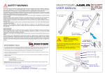
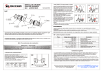
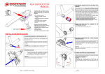
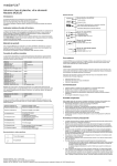
What is Rotor System and how does it work? 1. The dead point ROTOR RS4X USER MANUAL Rotor is an innovative pedalling system that eliminates the dead point. The dead point of conventional pedalling is the void that occurs when the pedals are vertically positioned (one at the top and the other at the bottom), which is a moment at which neither leg can transmit any power. The dead point limits the cyclist's performance, causes tendonitis and injuries to the knee, as well as discontinuity in the traction. Rotor System provides the definitive solution to this inefficiency, which is typical of conventional pedalling, by definitively eliminating dead points. Rotor makes the cranks independent in such a way that they are not aligned at a fixed 180º, but rather the angle between them varies during the cycle in such a way that one pedal never coincides with the one below, thus avoiding power vacuums. By eliminating the dead point, Rotor optimises the effort of the cyclist and reduces the risk of injury, providing a notable increase in performance and more comfortable and healthy pedalling. Such an effect is achieved by the use of independent cranks that are synchronised by means of two links and an eccentric support where the chainrings are rotatably mounted, which vary the leverage during the cycle, adapting every moment the equivalent chainring size to the muscle power of the legs. 2. ROTOR regulation system The Rotor System is designed with several regulation points that vary the amount of muscular force required to move the cranks. The user has the ability to determine the correct regulation point, depending on their physical characteristics or the conditions in which they are going to use the Rotor System. These different regulation points are marked on the power plate in front of the right crank. The middle regulation point is recommended for the majority of users, however, it may be necessary to adjust or change the regulation point, especially for competition. The Rotor System is correctly regulated when the individual user feels most comfortable. The Rotor instantaneous equivalent chainring figure shows how the development varies during a cycle when the Rotor system is regulated at default Default regulation point regulation point. In order to understand the meaning of the regulation points we will look at the 58,8 equivalent chainring point: - In the middle (default) regulation mark the gap between the horizontal and the 58,8 point is about 27 degrees - When the Rotor is regulated one point higher (the next longer mark) the entire instantaneous chainring figure turns counter clock-wise 6 degrees so the 58,8 point approaches the horizontal. In this position the Rotor system requires more physical strenght. www.rotorbike.com 2004 ~ 2005 (rev Oct 2004) - If the Rotor is regulated one point lower (next shorter mark) the chainring figure will be turned 6 degrees clockwise. In this position the rotor requires lower physical strenght. The most important thing to notice is that the correct regulation point is that in which you feel comfortable using the system in all conditions (in flat riding or climbing, seated or standing). USER GUIDE CONTENTS SAFETY WARNING! This owner’s manual contains important and useful information regarding the proper installation, operation, care, and maintenance of your ROTORtm RS4X Crankset. Carefully read, follow and understand the instructions given in this manual. You should keep it in a safe place for future reference. 1. 2. 3. 4. 5. 6. 7. 8. 9. Contents of the package Rotor installation How to change the regulation point Rotor removal Maintenance Tips & tricks RS4X technical specifications Spare parts list & figures Warranty sheet with terms & conditions 1. CONTENTS OF THE PACKAGE Do not perform any modifications or adjustments that are not outlined in this manual. If you have any doubt whatsoever regarding your service or repair ability, please take your bicycle to a qualified repair shop. Incorrect installation or service may reduce performance, and could result in a dangerous situation leading to injury or death. Please have your bicycle regularly inspected by a qualified mechanic for any cracks, deformation, signs of fatigue or wear. Components that have experienced excessive wear, cracks, deformations or impacts need immediate replacement. Together with your Rotor Cranks and chainrings, you will find in the box: - Warranty sheet with your RS4X serial number. - Thread lock adhesive F43 (medium strength), - 8 aluminium bolts(4 in RD2 version) and 4 nuts for the chainrings, - 2 washers for the pedals, - 1 M6 bolt. - 1 Installation tube (axle-end shell) installed. Required tools for assembly (not included in the package): - Allen key/wrench 4mm, 5mm and 8mm, - Standard bottom bracket tool, - Adjustable wrench or 32mm wrench, - Grease remover, - Assembly grease, - Chain line measuring device; Caliper. M6 Bolt Failure to perform maintenance could drastically reduce your ROTORtm crankset life and performance. If you ever have any questions, please contact your mechanic or your nearest ROTOR dealer for additional information. Left Cup Installation tube 2. ROTOR RS4X INSTALLATION: 4. INSTALL THE LEFT CUP BY THREADING IT IN THE BB TUBE ONLY TWO OR THREE THREADS 1. CLEANING AND PREPARING THE BOTTOM BRACKET TUBE Make sure that the threading of the bottom bracket cage is compatible with your version of ROTOR RS4X: - Italian thread: 36 x 24 tpi - BSA: 1.370 x 24 tpi Use the splined Standard BB installation tool Rework the threading of the bottom bracket cage if it were necessary. Clean the frame's bottom bracket tube of all residue (grease, oil, dirt) with a solvent such as Finish Line Citrus Biosolvent and thoroughly dry the area. Important: 5. ONLY FOR THE INSTALLATION OF A TRIPLE CHAINRING MODEL (MTB or Road) If the BB tube is not completely clean of lubricant residue and moisture, the thread locking adhesive will not work properly. LEFT CRANK BOLT It is absolutely necessary the installation of the inner chainring on these Rotors (MTB & Road triple) so the spider bearing be properly fixed 2. PREPARING THE ROTOR - Slide the left BB cup (Left-hand Adaptor) off of the spindle. Left BB cup is a precision fit on the spindle so it will simply slide off of the BB spindle. Place, the 3rd (small) chainring onto the eccentric of the Rotor. Do not yet fasten the chainring using the bolts (See illustration). This step will prevent damaging the front derailleur and the chain stay, and allow placement of the other two chainrings later in the installation process. - Tighten the M6 bolt on the eccentric (see illustration). - Do not yet take off the left crank bolt. If the head of the M6 bolt is touching the crank arm and preventing you from threading it into the hole, you can change the position of the hole simply by holding the crank & turning the BB cartridge. The tolerance between the M6 bolt head and crank arm is close. If you don’t want to use the 3rd (small) chainring, for example for “Single Speed”, you can substitute it with an specific inner plate which protects the spider bearing. This is an optional item. Important: Make sure that the bolt-head impressions on the chainring are facing the frame of the bicycle. Important: Before mounting the Rotor system, we recommend that you remove the chainrings to avoid damaging the front derailleur. Be certain to give the M6 bolt, this Instruction Manual & the original box to the rotorized cyclist, for their future reference. Only for MTB: Screw the right locknut on the bottom bracket. This is necessary if the bike has an E type derailleur in order to assure it to the bottom bracket. 6. SCREWING THE ROTOR INTO THE BOTTOM BRACKET 3. APPLY MEDIUM STRENGTH (BLUE COLOR, REMOVABLE) THREAD LOCK ADHESIVE Apply a sufficient amount of medium strength thread lock adhesive F43 (removable anaerobic resin like LOCTITE 243) on the threads of the right side of the BB tube, ensuring that the first threads are fully covered with the adhesive. Also apply a little bit of medium strength thread lock adhesive to the threads on the left side of the BB tube. Screw the Rotor (by hand and without force) onto the BB tube by turning the right crank counter-clockwise for English thread frames or clockwise for Italian thread frames. - You must use medium strength thread locking adhesive (removable) to correctly install the Rotor eccentric. A small amount, sufficient for the first installation, is included with your Rotor. Important: - NEVER use any type of grease during this assembly step: if grease has been used, the mechanism will not properly secure and the regulation points will fail while pedaling. - NEVER use high strength thread locking adhesive. Using it could prevent the extraction of the Rotor system in the future and/or seriously damage the threads of the bottom bracket tube. Do not screw on completely! ITA BSA If the Rotor does not easily screw into the BB tube, it is recommended that a thread-chasing tool be used to clean and sharpen the BB threads (English or Italian thread depending on the bike). 9. FASTENING THE ROTOR 7. MEASURING THE Q-FACTOR 85 mm MTB A) Carefully turn the right crank in the same direction as the pedaling motion (clockwise) as far as the M6 bolt permits without changing the previously set regulation point. Screw the Rotor into the threads until the distance between the outside part of the right crank (at the pedal hole) and the center of the seat tube of the bicycle measures approximately: B) While holding the right crank with the left hand, tighten the BB left cup with the right hand. - 75.5 mm for 2 chainring Road (Chainline 44mm) C) Strongly tighten the BB left cup (approximately 52-55 lb·ft or 70-75 N·m). - 80 mm for 3 chainring Road (Chainline 45mm) - 85 mm for MTB (Chainline 50mm) To facilitate the measuring procedure and improve accuracy: first measure the seat tube diameter, then add half diameter to the above measurement. This allows you to measure to the outside of the seat tube instead of the center of the seat tube. Each time we screw or unscrew the Rotor one 360 degree revolution, the system moves in or out approximately 1mm. Finally, screw the whole BB left cup but without tighten. 8. REGULATING THE ROTOR To correctly align the Rotor it is important that the tires are properly inflated and that the bicycle is standing in a horizontal position on a level surface with the right crank pointed towards the floor, creating a 90º angle. Position the system by pushing or pulling the right crank against the M6 bolt, raising or lowering the eccentric so that the reference triangle (inside triangle) coincides with the triangle on the “spider wheel.” In order to check the set regulation mark, position the right crank pointed downwards again. TIGHTEN HOLD D) Check to see that the desired regulation point is set and did not move during the tightening process. E) Only on MTB model: - fasten the left locknut but not too tight because this is only an aesthetics item - fasten the right locknut. Important: -The tightening of the left BB cup (Left-hand Adaptor) is very important because the left BB cup secures the Rotor System. The left BB cup is not an adjusting cup, it is a locking cup. -Tightening the cup should be completed in a progressive process and without sudden jerks or pulls, which could change the positioning of the regulation points. In case the positioning of the regulation point has been moved, it is necessary to repeat the "Regulating the Rotor" procedure in step #8. 10 REMOVE THE M6 BOLT FROM THE ECCENTRIC Remove the M6 bolt using a 5mm Allen key/hex wrench. There are five possible regulation marks, with a triangle showing the medium mark. We recommend this middle regulation, however, positioning depends on each user’s physical characteristics, form of pedaling, etc. 90º The correct regulation point is that in which you feel comfortable using the system in all conditions (in flat riding or climbing, seated or standing). Advices, if you are thinking regarding change regulation: * if you feel better pedaling seated than standing...you should regulate the next shorter mark * if you feel better pedaling standing than seated...you should regulate the next longer mark or: * if you feel better riding flat than climbing...you should regulate the next shorter mark * if you feel better riding uphill than flat...you should regulate the next longer mark Different marks also help to correct different positions of the rider, as example in the extreme, if the cranks are going to be assembled to a recumbent, the eccentric should be fitted rotated ~90º CCW, and so take references with the right crank pointing horizontal to the front. Note for recumbent bike installation: You´ll find specific recumbent installation & regulation instructions at the Supplement to RS4X Instruction Manual for Recumbent bikes. 11 PLACING THE CHAINRINGS, BEGINNING WITH THE 2nd CHAINRING Maneuver the right crank so that it is pointed to a 4 o’clock position (down and forward) to facilitate the placement of the 2nd chainring on the Rotor. Make sure that the bolt-head impressions on the 2nd chainring are facing the frame of the bicycle. The chainrings has a small arrow on the outside surface. Use this arrow as a reference and place the chainrings so that this arrow points towards the pedal hole in the right crank. Place the 1st (largest) chainring on the Rotor. We recommend mounting the chainring bolts for the 1st and 2nd chainrings with assembly grease, which often prevents inadvertent loosening. Finally, in the event of a triple chainring model, secure the 3rd chainring with the installation bolts. If there is a reference arrow on the 3rd chainring it should be aligned pointed towards the pedal hole (a chainring with 24 teeth does not have a reference arrow). Chainrings bolt tightening torque 5.9 lb·ft or 8 N·m 12 REMOVE THE INSTALLATION TUBE 3. STEPS TO CHANGE THE REGULATION POINT 1. Remove the left crank. - Using an 8mm Allen/hex tool, remove the left crank bolt and take off the installation tube. - This shell is only for installation purposes and is not necessary for Rotor operation. 2. Put on the installation tube (see step 12) and fasten the left crank bolt. This step is necessary to avoid axle movement while regulation process. 3. Tighten the M6 bolt on the eccentric. 4. Using the standard bottom bracket tool, loosen the left BB cup (Left-hand Adaptor): 2 turns is enough. 5. Turn the right crank up or down, pushing the M6 bolt, moving the eccentric to the new desired point. Look at step 8 of the Installation Instructions. 13 INSTALLING THE LEFT CRANK - If necessary install the left crank to apply more force unscrewing 6. Repeat steps 9 thru 12 of the Installation Instructions to complete the process. - Degrease the axle and the hexadrive crank head. - Be sure that the 4mm Allen bolts are not tight. - Using the 8mm Allen tool, tighten the left-crank fixing bolt while watching to be certain the left crank is correctly fixed & touching the outer positioning tube. Tighten the bolt up to 15 N·m or 10 lb·ft - Using an 4mm Allen tool, tighten the pair of 4mm faced Allen bolts up to 10 N·m or 7 lb·ft. Note: If you change the regulation point several times, we strongly recommend that you finally remove the Rotor and follow the installation instructions from the beginning in order to ensure that the thread locking adhesive securely holds the Rotor and prevents movement within the BB tube threads. 4. STEPS TO REMOVE THE ROTOR 1. Remove the chainrings. 2. Remove the left crank. 3. Put on the installation tube (see step 12) and fasten the left crank bolt. This step is necessary to avoid axle movement while disassembly process. 14 BEFORE INSTALLING THE PEDALS, PUT A WASHER (PROVIDED) INTO THE INSET POSITION LOCATED AT EACH PEDAL HOLE 4. Tighten the M6 bolt on the eccentric. 5. Using the standard bottom bracket tool, loosen the left BB cup (Left-hand Adaptor): 2 turns is enough. - Pedal tightening torque is 29.5 lb·ft or 40 N·m 6. Turn the right crank, unscrewing the Rotor until it is completely removed. - If necessary install the left crank to apply more force unscrewing 7. Take off the left BB cup (Left-hand Adaptor). 5. MAINTENANCE Washing: IMPORTANT: - Do not ride your bike immediately after the assembly procedure. Your bike should not be used for the following 2 ~ 3 hours; you must allow adequate time for the thread adhesive to dry completely, to prevent movement of the Regulation Point. - For some cyclists to attain the athletic benefits of the Rotor system, a time period of 2 to 3 weeks and up to 3 to 4 months, depending on the characteristics of the cyclist, may be required. NEVER spray (shoot) water against the Rotor System; this will enable water to enter into the bearings, creating oxidization (rust) leading to mechanical problems with the Rotor System. You may ride in wet conditions (i.e. in rain, through streams/rivers) but we strongly recommend to rinse off the Rotor System using a damp cloth after your ride. Lubricating the RS4X: - Even riding under water, as long as there is no significant pressure shooting water at the Rotor System, the bearings should be fine. - Every time you lubricate the chain, put several drops of oil over each o-ring on the pivot links. (There are 2 pivot links and 2 o-rings on each link). At least once per year, two months of intensive or winter use or every 4,000 miles, whichever occurs first, we recommend that the bearings in the links and the main axle be lubricated. 6.- TIPS & TRICKS We recommend that a qualified professional bicycle mechanic do this, but if you prefer to do it yourself, you will need an 4mm and 8mm Allen/hex tools only. 1. Be certain the fixing-bolts of the left-crank are properly tightened, so the crank is secured on the spindle. 2. Be certain the chainring bolts and nuts are securely tightened. 3. Be certain the regulation point of the Rotor system is where you want it and that it has not slipped or moved. 4. Be certain the chainline is correctly measured. 5. Be certain the chain is not over wear and correctly lubricated. 6. Be certain the front derailleur is correctly positioned and regulated. We recommend that you check these points regularly: 7. ROTOR RS4X TECHNICAL SPECIFICATIONS. For this maintenance process you will disassemble the system in main modules that configure the mechanism, and proceed as follows: 1. Remove the left crank. 2. Take out the axle with the right crank, pushing from the left side of the axle and pulling from the right crank. 3. Take the links in your hands, taking care not to loose the 4 o-rings. 4. Clean and lubricate the axle bearings, the link bearings and the o-rings. 5. Reassemble the system following previous steps 4, 3, 2 & 1. (Note: It is not necessary to remove the chainrings) The required frequency of greasing depends on the conditions of use. If not exposed to water/wet/muddy conditions, simply lubricate these bearing once every year, or every 4,000 miles. If the Rotor System is very exposed to water/wet/muddy conditions, we suggest a cleaning and lubrication within 2 months, or always that the whole bike need a big wash and regreased all the parts. We recommend that you use a high quality lubricant, such as FINISH LINE TEFLON-FORTIFIED GREASE. Visit www.finishlineusa.com to locate a licensed Finish Line retailer in your area. The main bearing & most important bearing in the Rotor System is the bearing located inside the spider. This is a sealed bearing, however it is very important that a direct pressurized stream of water never comes into contact with this bearing or area. If you believe that there is a problem, i.e. oxidation, with this bearing, we recommend that you contact an authorized Rotor Technician to make the necessary cleaning & lubricating, or replacement. Model Default Chainrings Crank Lenghts (mm) Weight (Kg) Axle lengths (mm) Chainline (mm) Q-Factor (mm) MTB 44-34-24 46-34-24 155, 165, 170, 172.5, 175, 180 Ti: 1.195 S: 1.280 143 50 170 RD2 53-39 52-39 52-36 155, 165, 170, 172.5 175, 180 Ti:1.190 S:1.280 124 44 151 RD3 53,39,30 52,39,30 155, 165, 170, 172.5, 175, 180 Ti:1.210 S:1.300 133 45 160 Extras Optional MTB: Free-Ride Bashguard, Inner Plate for “Single Speed” Optional chainrings: Outer for ROAD: 50, 53 or 54, 55, 56, 58 & 60 T (& 46T RCK compatible) Inner for RD2: 36, 39, 40, 42, 44 T Medium for RD3: 39, 42, 44 T (& 36 RCK compatible) Small for RD3: 26 & 30 T 8.- SPARE PARTS LIST Qty Qty Name Fig 1 1 Assembly Cartridge RS4X 1 ASSEMBLY 1 Eccentric RS4X 1.1 PART 1 Assembly left cup RS4X 1.2 ASSEMBLY 1 Seal G28x22x4 1.7 PART 1 Left Cup 1.8 PART 1 O-ring 29.75x1 1.9 PART 1 Bearing RNA6902 1.3 PART 1 Bearing 61810Y-2RS 1.4 PART 1 Seal G28x22x4 1.5 PART 1 Snap ring 50 1.6 PART 1 Assembly axle RS4X 2 Name Fig Type Type ASSEMBLY Assembly right crank RS4X 4 ASSEMBLY 1 Bearing 3003 RS 4.1 PART 1 Seal G28x22x4 4.2 PART 1 Right crank bolt 4.3 PART 1 Pivot RS4X 4.4 PART 1 Inner ring IR_9x12 4.5 PART 1 Pedal washer 4.6 PART 1 Right crank RS4X 4.7 PART 2 Assembly link_RS4X 5 ASSEMBLY 2 Link RS4X 5.1 PART 4 Bearing HK1214_RS 5.2 PART 4 O-ring 17.5x1.5 5.3 PART 1 Outer positioning tube RS4X 2.1 PART 1 Axle RS4X 2.2 PART 1 Bearing 61903-2RS 2.3 PART 1 Power plate RS4X 7.1 PART 1 Inner ring IR17x20x20.5 2.4 PART 2 Pivot RS4X 7.2 PART 1 Inner positioning tube 2.5 PART 2 Pivot inner ring_IR_9x12 7.3 PART 1 Transfer arm RS4X 2.6 PART 1 Chainrings RS4X ASSEMBLY 1 Pivot RS4X 2.7 PART 4 Al_chainring nut PART 1 Inner ring IR 9x12 2.8 PART 8 Al_chainring bolt PART 1 Left installation tube RS4X 1 O-ring 17x1_10 1 Assembly Left Crank 1 Assembly spider RS4X 7 ASSEMBLY PART 2.9 3 PART ASSEMBLY 1 Left crank Spline 3.1 PART 1 Left crank axle bolt 3.2 PART 2 Left crank M5 bolt 3.3 PART 1 Pedal washer 3.4 PART ROAD RD2 VERSION SPECIALS 1 Spider Inner plate 7.4 PART 4 Torx bolt 7.5 PART 6 PART 6 PART MTB VERSION SPECIALS 1 1 Left locknut for BSA threading Right locknut for BSA threading CARTRIDGE Fig 1 LEFT CUP Fig 1 Assembly axle 1.7 1.8 1.9 Assembly cartridge with left cup LEFT CRANK Fig 3 2.1 2.9 1.2 2.3 2.5 1.1 LINK Fig 6 SPIDER - POWER PLATE Fig 5 2.4 1.3 2.7 2.2 1.4 AXLE Fig 2 2.8 1.6 2.6 1.5 Fig 2 Fig 1 RIGHT CRANK Fig 4 RS4X MODULAR ASSEMBLY 3.3 5.2 5.1 3.1 7.3 7.1 ASSEMBLY SPIDER - POWER PLATE 5.3 ASSEMBLY LINK 3.3 3.2 ASSEMBLY LEFT CRANK 7.2 5.2 5.3 Fig 5 Fig 3 3.4 4.1 7.5 7.4 MTB RS4X ONLY LOCKNUT 4.2 4.3 4.4 4.5 RD2 MTB-RD3 4.7 ASSEMBLY RIGHT CRANK 4.6 Fig 7 Fig 6 Fig 4 WARRANTY REGISTRATION Serial Number: Full name:________________________________________________________ Address:_________________________________________________________ Phone: __________________________________________________________ Date of purchase:__________________________________________________ Retailer seal:______________________________________________________ Type of use: recreational advanced professional Age: ________ Suggestions: _____________________________________________________ ________________________________________________________________ ________________________________________________________________ ROTOR WARRANTY POLICY: The ROTOR and its components are guaranteed for 2 YEARS against any manufacturer defects or defective materials. In the event of a warranty defect, Rotor´s sole obligation under this warranty is to repair or replace, at its option, the defective part or product at no charge. Moreover, in some countries, Rotor is obligued to ensure any legal warranty defined by law for the customer´s protection. Elements subject to wear and breakdowns that the manufacturer is not responsible for, are not covered by this warranty. Failures or breakdowns caused by improper use, poor assembly or inadequate maintenance as declared in the instructions or the user manual are not covered by this warranty. Always keep your receipt or invoice, this warranty does not cover products whose serial number or identification has been erased, damaged or modified. The following acts void this warranty: ♦ Failure to fulfill the requirements above. ♦ Improper installation. ♦ Improper use or installation of inadequate parts. www.rotorbike.com Rotor Componentes Tecnológicos SL - [email protected] Ctra. Torrejón-Ajalvir, Km3’300 AJALVIR – MADRID – SPAIN Tel. +34 918843846 Fax. +34 918843865 www.rotorbike.com