1
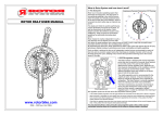
RS4 INSTRUCTION
MANUAL
3. APPLY MEDIUM STRENGTH (BLUE COLOR) THREAD LOCK
ADHESIVE.
Apply a sufficient amount of medium strength thread lock adhesive
F43 (anaerobic resin like LOCTITE 243) on the threads of the right
side of the BB tube, ensuring that the first threads are sufficiently
covered with the adhesive. Also apply a little bit of medium strength
thread lock adhesive to the threads on the left side of the BB tube.
- You must use medium strength thread locking adhesive to
correctly install the Rotor eccentric. A small amount, sufficient for
the first installation, is included with your Rotor.
- NEVER use any type of grease during this assembly step: if
grease has been used, the mechanism will not properly secure
and the regulation points will change while pedaling.
- NEVER use a thread locking adhesive other than medium
strength. Using a different strength could prevent the
extraction of the Rotor system in the future and/or seriously
damage the threads of the bottom bracket tube.
Together with your Rotor Cranks,
BB and chainrings, you will find in
the box:
- RS4 instruction manual,
- warranty sheet with the serial
number,
- thread lock adhesive F43 (medium
strength),
- bolts & nuts for the chainrings,
- two washers for the pedals,
- M6 bolt.
4. INSTALL THE LEFT CUP
APPROXIMATELY HALF WAY
Required Tools for assembly:
-Allen key/Hex wrench 5mm and 8mm
-Standard bottom bracket tool
-Adjustable wrench or 32mm wrench
-Grease remover
-Assembly Grease
-Chain line measuring device: Caliper
BY
SCREWING
IT
ON
Use the spindled Standard BB installation tool.
INSTALLATION INSTRUCTIONS
1. CLEANING AND PREPARING THE BOTTOM BRACKET TUBE
5. ONLY FOR THE INSTALLATION OF A TRIPLE CHAINRING
MODEL (MTB or Road)
Clean the frame's bottom bracket tube of all residue (grease, oil,
dirt) with a solvent such as Finish Line Citrus Biosolvent and
thoroughly dry the area.
Place, the 3rd (small) chainring onto the eccentric of the Rotor. Do
not yet fasten the chainring using the bolts (See illustration). This
step will prevent damaging the front derailleur and the chain stay,
and allow placement of the other two chainrings later in the
installation process.
You may need to clean and/or dress the threads in the BB tube
using a thread chasing tool (English or Italian thread, depending on
the bike)
Important:
If the BB tube is not completely clean of lubricant residue and
moisture, the thread locking adhesive will not work properly.
Important:
Make sure that the bolt-head impressions on the chainring are
facing the frame of the bicycle.
2. PREPARING THE ROTOR
1
-
Take off the left crank. Slide the left BB cup (Left-hand
Adaptor) off of the spindle. The left BB cup is a precision fit
on the spindle so it will simply slide off of the BB spindle.
Tighten the M6 screw on the eccentric (see illustration).
6. SCREWING THE ROTOR INTO THE BOTTOM BRACKET
Screw the Rotor (by hand and without force) onto the BB tube by
turning the right crank counter-clockwise for English thread frames
or clockwise for Italian thread frames.
Do not screw on completely!
Important:
If the Rotor does not easily screw into the BB tube, it is
recommended that a thread-chasing tool be used to clean and
sharpen the BB threads (English or Italian thread depending on the
bike).
Important:
Before mounting the Rotor system, we recommend that you remove
the chainrings to avoid damaging the front derailleur.
ITA
Page 1. Text Release January 2004
BSA
Page 2
11. PLACING THE CHAINRINGS, BEGINNING WITH THE 2nd
CHAINRING
Maneuver the right crank so that it is pointed to a 4 o’clock position
nd
(down and forward) to facilitate the placement of the 2 chainring
on the Rotor.
nd
Make sure that the bolt-head impressions on the 2 chainring are
facing the frame of the bicycle.
The chainrings has a small arrow on the outside surface. Use this
arrow as a reference and place the chainrings so that this arrow
points towards the pedal hole in the right crank.
Place the 1st (largest) chainring on the Rotor.
We recommend mounting the chainring bolts for the 1st and 2nd
chainrings with assembly grease, which often prevents inadvertent
loosening.
Finally, in the event of a triple chainring model, secure the 3rd
chainring with the installation bolts. If there is a reference arrow on
rd
the 3 chainring it should be aligned pointed towards the pedal hole
(a chainring with 24 teeth does not have a reference arrow).
7. MEASURING THE CHAIN LINE
Screw the Rotor into the threads until the distance between the
outside part of the right crank (at the pedal hole) and the center of
the seat tube of the bicycle measures approximately:
- 75.5 mm for 2 chainring Road.
- 80 mm for 3 chainring Road.
- 82.5 mm for MTB XC (chain line 47.5mm)
- 84.5 mm for MTB Free Ride (chain line 49.5mm)
Note:
To facilitate the measuring procedure and improve accuracy: first
measure the seat tube diameter, then add half of this distance to the
above measurement. This allows you to measure to the outside of
the seat tube instead of the center of the seat tube.
Each time we screw or unscrew the Rotor one 360 degree
revolution, the system moves in or out approximately 1mm.
90º
8. REGULATING THE ROTOR
To correctly align the Rotor it is important that the tires are properly
inflated and that the bicycle is standing in a horizontal position on a
level surface with the right crank pointed towards the floor, creating
a 90º angle. Position the system by pushing or pulling the right
crank against the M6 screw, raising or lowering the eccentric so that
the reference point (inside triangle) coincides with the triangle on the
“spider wheel.” In order to check the set regulation point, position
the right crank pointed downwards again.
There are five possible regulation points, with the triangle being the
third (always counting from the top). We recommend this middle
regulation, however, positioning depends on each user’s physical
characteristics, form of pedaling, etc. With lower points, more
comfort during climbs (lower muscular requirement) will be
achieved, while with the higher points the cyclist will achieve higher
top speeds, requiring more muscular effort.
Usually XC and TT competitors prefer using the system regulated
with the reference triangle positioned in the middle or at one point
above the triangle; while road cyclists prefer to ride with the system
regulated at the reference triangle or one point below the triangle.
12.
INSTALLING THE LEFT CRANK
•
•
•
9. FASTENING THE ROTOR
Degrease the axle and the crank square tapered head.
We recommend that you use medium strength thread
locking on the threads of the BB spindle (required on the
titanium model).
Using an 8mm Allen/hex tool, tighten the left-crank fixing
bolt while watching to be certain the left crank is correctly &
evenly pulling tight on the taper of the BB spindle. Tighten
the bolt to 25.9 lb·ft or 35 N·m.
1
- Carefully turn the right crank in the same direction as the pedaling
motion (clockwise) as far as the M6 screw permits without changing
the previously set regulation point.
- While holding the right crank with the left hand, tighten the left cup
with the right hand.
- Strongly tighten the left cup (approximately 52-55 lb·ft or 70-75
N·m).
- Check to see that the desired regulation point is set and did not
move during the tightening process.
13.
BEFORE INSTALLING THE PEDALS, PUT A
WASHER (PROVIDED) INTO THE INSET
POSITION LOCATED AT EACH PEDAL
HOLE.
Pedal tightening torque is 29.5 lb·ft or 40 N·m
Important:
-The tightening of the left BB cup (Left-hand Adaptor) is very
important because the left BB cup, secures the Rotor System. The
left BB cup is not an adjusting cup, it is a locking cup.
-Tightening the cup should be completed in a progressive process
and without sudden jerks or pulls, which could change the
positioning of the regulation points. In case the positioning of the
regulation point has been moved, it is necessary to repeat the
"Regulating the Rotor" procedure in step #8.
10. REMOVE THE M6 SCREW FROM THE ECCENTRIC
Remove the M6 screw using a 5mm Allen key/hex wrench.
Page 3
IMPORTANT:
-
Do not ride your bike immediately after the assembly procedure. Your bike should not be used for the
following 2 ~ 3 hours; you must allow adequate time for the thread adhesive to dry completely, to
prevent movement of the Regulation Point.
-
The correct regulation point is that in which you feel comfortable using the system in all conditions (in flat
riding or climbing, seated or standing).
-
For some cyclists to attain the athletic benefits of the Rotor system, a time period of 2 to 3 weeks and up
to 3 to 4 months, depending on the characteristics of the cyclist, may be required.
Page 4
STEPS TO CHANGE THE REGULATION POINT
1. Remove the left crank.
2. Tighten the M6 screw on the eccentric.
3. Using the standard bottom bracket tool, loosen the left BB cup (Left-hand Adaptor): 2 turns is
enough.
4. Turn the right crank up or down, pushing the M6 screw, moving the eccentric to the new desired
point. Look at step 8 of the Installation Instructions.
5. Repeat steps 9 thru 12 of the Installation Instructions to complete the process.
Note: If you change the regulation point several times, we recommend that you finally remove the Rotor and
follow the installation instructions from the beginning in order to ensure that the thread locking adhesive securely
holds the Rotor and prevents movement within the BB tube threads.
STEPS TO REMOVE THE ROTOR
1.
2.
3.
4.
5.
Remove the chainrings.
Remove the left crank.
Tighten the M6 screw on the eccentric.
Using the standard bottom bracket tool loosen the left BB cup (Left-hand Adaptor): 2 turns is enough.
Turn the right crank, unscrewing the Rotor until it is completely removed. If necessary use a left crank
to apply more force unscrewing.
6. Take off the left BB cup (Left-hand Adaptor).
At least once per year, or every 8,000 miles, whichever occurs first, we recommend that the
bearings in the links and the main axle be lubricated.
We recommend that a qualified professional bicycle mechanic do this, but if you prefer to do it
yourself, you will need the URS4 tool (see drawing), which is available for sale from most Rotor
resellers.
For this maintenance process you will disassemble the system
in main modules that configure the mechanism, and proceed
as follows:
1. Remove the left crank.
2. Remove the axle fixing nut, using the URS4 tool.
3. Take out the axle with the right crank, pushing from the left
side of the axle and pulling from the right crank.
4. Take the links in your hands, taking care not to loose the 4
o-rings.
5. Clean and lubricate the axle bearings, the link bearings and the o-rings.
6. Reassemble the system following previous steps 4, 3, 2 & 1.
Note: It is not necessary to remove the chainrings.
MAINTENANCE
Washing
NEVER spray (shoot) water against the Rotor System; this will enable water to enter into the
bearings, creating oxidization (rust) leading to mechanical problems with the Rotor System.
You may ride in wet conditions (i.e. in rain, through streams/rivers) and you may gently rinse off
the Rotor System using a damp cloth.
Helpful tips
We recommend that you check these points regularly:
1. Be certain the fixing-bolt of the left-crank is tight, so the crank is tight on the spindle.
2. Be certain the chainring bolts and nuts are securely tightened.
3. Be certain the regulation point of the Rotor system is where you want it and that it has not slipped or moved.
Lubricating the RS4
Even riding under water, as long as there is no
significant pressure shooting water at the Rotor
System, the bearings should be fine.
Every time you lubricate the chain, put a drop of oil
over each o-ring on the pivot links. (There are 2 pivot
links and 2 o-rings on each link).
The required frequency of greasing depends on the conditions of use. If not exposed to
water/wet/muddy conditions, simply lubricate these bearing once every year, or every 8,000 miles.
If the Rotor System is very exposed to water/wet/muddy conditions, we suggest a cleaning and
lubrication within 2 months.
We recommend that you use a high quality lubricant, such as FINISH LINE
TEFLON-FORTIFIED GREASE. Visit www.finishlineusa.com to locate a licensed
Finish Line retailer in your area.
The main bearing & most important bearing in the Rotor System is the bearing located
inside the spider. This is a sealed bearing, however it is very important that a direct pressurized
stream of water never comes into contact with this bearing or area. If you believe that there is a
problem, i.e. oxidation, with this bearing, we recommend that you contact an authorized Rotor
Technician to make the necessary cleaning & lubricating, or replacement.
Page 5
Page 6