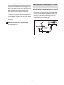
1
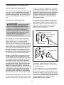
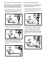
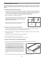
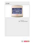
Model No. VFMTL1206.0
Serial No.
The serial number is found in the
location shown below. Write the
serial number in the space above.
Serial Number Decal
At FreeMotion Fitness, we’re
committed to providing complete customer satisfaction. If
you have questions, see HOW
TO CONTACT CUSTOMER
CARE on the back cover of this
manual.
CAUTION
Read all precautions and instructions in this manual before
using this equipment. Keep this
manual for future reference.
USER'S MANUAL
TABLE OF CONTENTS
IMPORTANT PRECAUTIONS . . . . . . . . . . . . . . . . . . . . . . . . . . . . . . . . . . . . . . . . . . . . . . . . . . . . . . . . . . . . . . . . .3
BEFORE YOU BEGIN . . . . . . . . . . . . . . . . . . . . . . . . . . . . . . . . . . . . . . . . . . . . . . . . . . . . . . . . . . . . . . . . . . . . . . .6
ASSEMBLY . . . . . . . . . . . . . . . . . . . . . . . . . . . . . . . . . . . . . . . . . . . . . . . . . . . . . . . . . . . . . . . . . . . . . . . . . . . . . . .7
HOW TO USE THE CHEST PULSE SENSOR . . . . . . . . . . . . . . . . . . . . . . . . . . . . . . . . . . . . . . . . . . . . . . . . . . .10
TREADMILL OPERATION . . . . . . . . . . . . . . . . . . . . . . . . . . . . . . . . . . . . . . . . . . . . . . . . . . . . . . . . . . . . . . . . . . .11
TROUBLESHOOTING . . . . . . . . . . . . . . . . . . . . . . . . . . . . . . . . . . . . . . . . . . . . . . . . . . . . . . . . . . . . . . . . . . . . . .25
SIX-MONTH PREVENTIVE MAINTENANCE RECORD . . . . . . . . . . . . . . . . . . . . . . . . . . . . . . . . . . . . . . . . . . . .29
EXERCISE GUIDELINES . . . . . . . . . . . . . . . . . . . . . . . . . . . . . . . . . . . . . . . . . . . . . . . . . . . . . . . . . . . . . . . . . . .30
PART LIST . . . . . . . . . . . . . . . . . . . . . . . . . . . . . . . . . . . . . . . . . . . . . . . . . . . . . . . . . . . . . . . . . . . . . . . . . . . . . . .32
EXPLODED DRAWING . . . . . . . . . . . . . . . . . . . . . . . . . . . . . . . . . . . . . . . . . . . . . . . . . . . . . . . . . . . . . . . . . . . . .34
FREEMOTION is a registered trademark of ICON IP, Inc.
2
IMPORTANT PRECAUTIONS
WARNING:
To reduce the risk of burns, fire, electric shock, or injury to persons, read the
following important precautions and information before operating the treadmill.
1. It is the responsibility of the owner to ensure
that all users of the treadmill are adequately
informed of all warnings and precautions.
order part number 146148, or see your local
electronics store.
12. Failure to use a properly functioning surge
suppressor could result in damage to the control system of the treadmill. If the control system is damaged, the walking belt may change
speed, accelerate, or stop unexpectedly,
which may result in a fall and serious injury.
2. Use the treadmill only as described.
3. Place the treadmill on a level surface, with at
least eight feet of clearance behind it and two
feet on each side. Do not place the treadmill
on any surface that blocks air openings. To
protect the floor or carpet from damage, place
a mat under the treadmill.
13. Keep the power cord and the surge suppressor away from heated surfaces.
4. Keep the treadmill indoors, away from moisture and dust. Do not place the treadmill in a
garage or covered patio, or near water.
14. Never move the walking belt while the power
is turned off. Do not operate the treadmill if
the power cord or plug is damaged or if the
treadmill is not working properly. (See TROUBLESHOOTING on page 25 if the treadmill is
not working properly.)
5. Do not operate the treadmill where aerosol
products are used or where oxygen is being
administered.
15. Read, understand, and test the emergency
stop procedure before using the treadmill (see
step 3 on page 13).
6. Do not operate the treadmill until it is properly
assembled (see ASSEMBLY on page 7).
7. Inspect and properly tighten all parts of the
treadmill regularly.
16. Never start the treadmill while you are standing on the walking belt. Always hold the
handrails while using the treadmill.
8. Keep children under the age of 12 and pets
away from the treadmill at all times.
17. The treadmill is capable of high speeds.
Adjust the speed in small increments to avoid
sudden jumps in speed.
9. The treadmill should not be used by persons
weighing more than 350 pounds. Do not allow
more than one person on the treadmill at a
time.
18. The pulse sensors are not medical devices.
Various factors, including the user's movement, may affect the accuracy of heart rate
readings. The pulse sensors are intended
only as an exercise aid in determining heart
rate trends in general.
10. When connecting the power cord (see page
9), plug the power cord into a surge suppressor (not included) and plug the surge suppressor into a grounded circuit capable of
carrying 15 or more amps. No other appliance
should be on the same circuit. Do not use an
extension cord.
19. Never leave the treadmill unattended while it is
running. Always remove the key, unplug the
power cord, and move the on/off switch to the
“off” position when the treadmill is not in use.
11. Use only a single-outlet surge suppressor
that meets all of the specifications described
on page 9. To purchase a surge suppressor,
call the toll-free Customer Care telephone
number on the back cover of this manual and
20. Do not change the incline of the treadmill by
placing objects under it.
3
tem, extreme care should be taken to keep
from touching such power lines or circuits, as
contact with them might be fatal.
21. Never insert or drop any object into any
opening.
22. Make sure to perform all maintenance procedures outlined in this manual. Failure to do so
will void the warranty and may result in damage to the treadmill.
23.
27. To reduce the risk of electric shock, do not remove the cover or the back of the television.
There are no user serviceable parts inside.
Refer servicing to qualified service personnel.
DANGER: Always unplug the power
28. Upon completion of any service or repairs to
the treadmill or the television, ask the service
technician to perform safety checks to confirm that the unit is in proper operating condition.
cord immediately after use, before cleaning
the treadmill, and before performing the maintenance and adjustment procedures described in this manual. Servicing other than
the procedures in this manual should be performed by an authorized service representative only.
• Use No. 10 AWG (5.3mm2) copper, No. 8
AWG (8.4mm2) aluminum, No. 17 AWG
(1.0mm2) copper-clad steel or bronze wire,
or larger as a ground wire.
24. The treadmill is intended for in-home use
only. Do not use the treadmill in a
commercial, rental, or institutional setting.
• Secure an antenna lead-in and ground wires
to the house with stand-off insulators
spaced from 4 to 6 feet (1.22 to 1.83m)
apart.
25. If an outside antenna or cable system is connected, make sure that the antenna or cable
system is grounded to provide some protection against voltage surges and built-up static
charges. Section 810 of the National
Electrical Code, ANSI/NFPA No. 70-1984, provides information with respect to proper
grounding of the mast and supporting structure, grounding of the lead-in wire to an antenna discharge unit, size of grounding conductors, location of antenna discharge unit,
connection to grounding electrodes, and requirements for the grounding electrode.
• Mount an antenna discharge unit as close
as possible to where the lead-in enters the
house.
• Use a jumper wire not smaller than No. 6
AWG (13.3mm2) copper, or the equivalent
when a separate antenna-grounding electrode is used. See NEC Section 810-21 (j).
Note to CATV system installer: This reminder is
provided to call the CATV system installer’s attention to Article 820-40 of the NEC that provides
guidelines for proper grounding and, in particular, specifies that the cable ground shall be connected to the grounding system of the building,
as close to the point of cable entry as practical.
26. An outside antenna system should not be located in the vicinity of overhead power lines
or other electric light or power circuits, or
where it can fall into such power lines or circuits. When installing an outside antenna sys-
4
Power Lines
Ground
Clamp
Service
Entrance
Conductors
Standoff
Insulators
Mast
To External Antenna
Terminal of Treadmill
Service
Entrance
Equipment
Antenna
Lead-in Wire
Ground
Wire
Antenna
Discharge Unit
Ground Wire
Power Service Grounding
Electrode System (e.g.
Interior Metal Water Pipe)
Ground
Clamps
Bonding
Jumper
Ground
Clamps
Optional Antenna Grounding Electrode Driven 8
Feet (2.44m) Into The Earth (If Required By Local
Codes). See NEC Section 810–21 (f).
WARNING:
Before beginning this or any exercise program, consult your physician. This
is especially important for persons over the age of 35 or persons with pre-existing health problems.
Read all instructions before using. ICON assumes no responsibility for personal injury or property
damage sustained by or through the use of this product.
SAVE THESE INSTRUCTIONS
The decal shown below is found on the treadmill in the indicated location. If the decal is missing or illegible, call the toll-free Customer Care telephone number on the back cover of this manual and order a free
replacement decal. Apply the decal in the location shown.
!
WARNING
Do not remove or insert this plug while the
safety key is inserted in the console. Touch
metal frame before removing or inserting plug.
Static sensitive components may be affected.
Underside
of Console
!
WARNING
Do not remove or insert this plug while the
safety key is inserted in the console. Touch
metal frame before removing or inserting plug.
Static sensitive components may be affected.
5
BEFORE YOU BEGIN
Congratulations for selecting the revolutionary
FREEMOTION® 3500 XLS treadmill. The 3500 XLS
treadmill offers an impressive array of features designed to help you achieve your fitness goals in the
convenience and privacy of your home.
help us assist you, please note the product model
number and serial number before contacting us. The
model number of the treadmill is VFMTL1206.0. The
serial number can be found on a decal attached to the
treadmill (see the front cover of this manual for the location of the decal).
For your benefit, read this manual carefully before
using the treadmill. If you have questions after reading this manual, see the front cover of this manual. To
Before reading further, please familiarize yourself with
the parts that are labeled in the drawing below.
Personal TV
Console
Accessory Tray
Water Bottle Holder*
Key/Clip
Handrail
Handgrip Pulse Sensor
Circuit Breaker
Walking Belt
On/off Switch
Foot Rail
Power Cord
Cushioned Walking Platform
*No water bottle is included
Roller Adjustment Bolts
6
ASSEMBLY
Assembly requires two persons. Set the treadmill in a cleared area and remove all packing materials. Do not
dispose of the packing materials until assembly is completed. Assembly can be completed using the included
hex keys.
Note: The underside of the treadmill walking belt is coated with high-performance lubricant. During shipping, a
small amount of lubricant may be transferred to the top of the walking belt or the shipping carton. This is a normal
condition and does not affect treadmill performance. If there is lubricant on top of the walking belt, simply wipe off
the lubricant with a soft cloth and a mild, non-abrasive cleaner.
1. Slide the Right and Left Uprights (95, 97) onto the brackets near the front of the Frame (76). Make sure that the
Uprights are on the correct sides; the indicated
holes must be facing inward.
Raise the Right Upright (95) until the lower hole in the
front of the Right Upright is aligned with the upper hole in
the bracket on the Frame (76). Finger tighten an Upright
Bolt (96) into the Right Upright and the bracket. Do not
tighten the Upright Bolt yet.
1
Holes
96
95
96
97
Repeat this step with the Left Upright (97).
76
2. While a second person holds the Handrail (91) near the
Uprights (95, 97), feed the Upright Wire Harness (100) in
the Handrail down into the Right Upright, and feed the TV
Cable (127) down into the Left Upright. Next, pull the ends
of the Upright Wire Harness and the TV Cable out of the
lower ends of the Uprights. If there are wire ties on the
ends of the Upright Wire Harness and the TV Cable, remove the wire ties. Then, set the Handrail on the Uprights.
2
89
86
99
91
85
99
Finger tighten eight Handrail Bolts (99) into the Uprights
(95, 97) and the Handrail (91). Do not tighten the
Handrail Bolts yet. Be careful to avoid pinching the
Upright Wire Harness (100) and the TV Cable (127).
127
99
100
95
97
Note: The CD Holder (86) and the Cup Holder (85) are
replaceable. If these parts become dislodged from the
Console Base (89), simply press them back in.
3. Connect the lower end of the TV Cable (127) on the left
side of the treadmill as shown.
3
95
Next, connect the Upright Wire Harness (100) to the
Power Wire Harness (57). The connectors should slide
together easily and snap into place. If they do not,
turn one connector and try again. Next, insert the connectors down into the hole in the Frame (76), and push
all the excess wire harness up into the Right Upright
(95). Make sure that the Wire Harnesses remain fully
connected.
76
100
127
7
57
4. Be careful to avoid pinching your hands, the Wire
Harnesses (not shown), or the TV Cable (not shown)
during this step.
4
99
While a second person holds the Uprights (95, 97), remove the two Upright Bolts (96) used in step 1. Next,
slide the Uprights fully onto the brackets on the Frame
(not shown). Attach each Upright with four Upright Bolts
(96) as shown. Firmly tighten all eight Upright Bolts.
99
99
97
95
Firmly tighten the eight Handrail Bolts (99).
96
96
5. Plug the indicated end of the Power Cord (48) fully into
the treadmill as shown.
5
48
6. After the treadmill is moved to the location where it will
be used (see HOW TO MOVE THE TREADMILL on
page 28), make sure that both Rear Feet (5) and both
Wheels (not shown) rest firmly on your floor. If the
treadmill rocks slightly on your floor, loosen the Rear
Foot Locknut (113) above the right Rear Foot. Turn the
right Rear Foot clockwise or counterclockwise until the
rocking motion is eliminated. Then, retighten the Rear
Foot Locknut.
7. Note the location of the 75 ohm antenna terminal on
the treadmill. For the television to operate properly,
an antenna, a 75 ohm CATV cable, or a VCR must be
connected to the 75 ohm antenna terminal (see page
9).
6
113
5
113
5
7
75 Ohm
Antenna Terminal
8. Make sure that all parts are properly tightened before you use the treadmill. Keep the included hex keys
for adjustment purposes. To protect the floor or carpet from damage, place a mat under the treadmill.
8
Before the personal television can be used, you must connect an antenna, a 75 ohm CATV cable, or a VCR
to the 75 ohm antenna terminal on the treadmill frame. Note: No antenna, cable, or adapter is included.
HOW TO CONNECT AN ANTENNA
300 Ohm Flat Wire
Indoor Antenna
1. See the drawing near the bottom of this page.
Connect the 300 ohm flat wire from the antenna to a
300 ohm to 75 ohm adapter.
1. Place a VHF
antenna in the
desired location. Connect
the 300 ohm
flat wire from
the antenna to
a 300 ohm to
75 ohm
adapter.
2. Press the 300
ohm to 75 ohm
adapter onto
the 75 ohm antenna terminal
on the treadmill
frame near the
power cord.
Screwdriver
2. Press the 300 ohm to 75 ohm adapter onto the 75
ohm antenna terminal on the treadmill frame near
the power cord.
VHF 300
Ohm Flat
Wire
75 Ohm CATV Cable
1. See the drawing near the bottom of this page.
Connect the 75 ohm CATV cable from the antenna
to the 75 ohm antenna terminal on the treadmill
frame near the power cord.
300 to 75 Ohm Adapter
HOW TO CONNECT A 75 OHM CATV CABLE
VHF
Antenna
1. Connect a 75 ohm
CATV cable to the 75
ohm antenna terminal
on the treadmill frame
near the power cord.
300 to 75 Ohm
Adapter
75 Ohm
Terminal
75 Ohm CATV Cable
75 Ohm Terminal
HOW TO CONNECT A VCR
Outdoor Antenna
1. Connect one end of a 75 ohm CATV cable to the
video output jack on your VCR.
Note: Outdoor antennas are subject to weathering that
can reduce signal quality. Inspect your antenna and
the lead-in wiring before connecting the antenna.
2. Plug in the power cord of your VCR. See your VCR
user’s manual for proper grounding instructions.
3. Connect the 75 ohm CATV cable to the 75 ohm antenna terminal on the treadmill frame near the power
cord.
Combination
VHF/UHF Antennas
300 Ohm
Flat Wire
300 to 75
Ohm Adapter
75 Ohm
Terminal
Note: To operate the television with your VCR, make
sure that channel 3 or 4 is selected.
75 Ohm
CATV Cable
75 Ohm CATV Cable
9
HOW TO USE THE CHEST PULSE SENSOR
HOW TO PUT ON THE CHEST PULSE SENSOR
The chest pulse sensor consists of two components—
the chest strap and the sensor unit (see the drawing
below). Insert the tab on one end of the chest strap into
the hole in one end of the sensor unit, as shown in the
inset drawing. The tab should be flush with the front of
the sensor unit.
each use, it may remain activated longer than necessary, draining the battery prematurely.
• Store the chest pulse sensor in a warm, dry place.
Do not store the chest pulse sensor in a plastic bag
or other container that may trap moisture.
• Do not expose the chest pulse sensor to direct
sunlight for extended periods of time; do not expose
it to temperatures above 122° Fahrenheit (50°
Celsius) or below 14° Fahrenheit (-10° Celsius).
• Do not excessively bend or stretch the sensor unit
when using or storing the chest pulse sensor.
Chest Strap
Tabs
Tab
• Clean the sensor unit using a damp cloth—never
use alcohol, abrasives, or chemicals. The chest
strap may be hand washed and air dried.
CHEST PULSE SENSOR TROUBLESHOOTING
Sensor Unit
Sensor
Unit
Buckle
Next, wrap the
chest pulse sensor around your
chest and attach
the other end of
the chest strap to
the sensor unit.
Adjust the length
of the chest strap,
if necessary. The
chest pulse sensor should be under your clothes, tight against your
skin, and as high under the pectoral muscles or
breasts as is comfortable. Make sure that the logo on
the sensor unit is facing forward and is right-side-up.
Pull the sensor unit away from your body a few inches
and locate the two electrode areas on the inner side
(the electrode areas are covered by shallow ridges).
Using saline solution such as saliva or contact lens solution, wet both electrode areas. Return the sensor unit
to a position against your chest.
The instructions on the following pages explain
how the chest pulse sensor is used with the console. If the chest pulse sensor does not function
properly, try the steps below.
• Make sure that you are wearing the chest pulse sensor as described at the left. Note: If the chest pulse
sensor does not function when positioned as described, move it slightly lower or higher on your
chest.
• Use saline solution such as saliva or contact lens
solution to wet the two electrode areas on the
sensor unit. If heart rate readings do not appear until
you begin perspiring, re-wet the electrode areas.
• As you walk or run on the treadmill, position yourself near the center of the walking belt. For the
console to display heart rate readings, the user
must be within arm’s length of the console.
• The chest pulse sensor is designed to work with
people who have normal heart rhythms. Heart rate
reading problems may be caused by medical
conditions such as premature ventricular contractions (pvcs), tachycardia bursts, and arrhythmia.
CHEST PULSE SENSOR CARE AND MAINTENANCE
• Thoroughly dry the chest pulse sensor after each
use. The chest pulse sensor is activated when the
electrode areas are wetted and the heart rate
monitor is put on; the chest pulse sensor shuts off
when it is removed and the electrode areas are
dried. If the chest pulse sensor is not dried after
• The operation of the chest pulse sensor can be
affected by magnetic interference caused by high
power lines or other sources. If it is suspected that
this is a problem, try relocating the treadmill.
• The CR2032 battery in the chest pulse sensor may
need to be replaced (see page 26).
10
TREADMILL OPERATION
THE PRE-LUBRICATED WALKING BELT
tric shock. This product is equipped with a cord having
an equipment-grounding conductor and a grounding
plug. Plug the power cord into a surge suppressor,
and plug the surge suppressor into an appropriate
outlet that is properly installed and grounded in
accordance with all local codes and ordinances.
Important: The treadmill is not compatible with
GFCI-equipped outlets.
Your treadmill features a walking belt coated with highperformance lubricant. IMPORTANT: Never apply silicone spray or other substances to the walking
belt or the walking platform. Such substances will
deteriorate the walking belt and cause excessive
wear.
HOW TO PLUG IN THE POWER CORD
This product is for use on a nominal 120-volt circuit,
and has a grounding plug that looks like the plug illustrated in drawing 1 below. A temporary adapter that
looks like the adapter illustrated in drawing 2 may be
used to connect the surge suppressor to a 2-pole
receptacle as shown in drawing 2 if a properly
grounded outlet is not available.
DANGER:
Improper connection
of the equipment-grounding conductor can
result in an increased risk of electric shock.
Check with a qualified electrician or serviceman if you are in doubt as to whether the
product is properly grounded. Do not modify
the plug provided with the product—if it will
not fit the outlet, have a proper outlet
installed by a qualified electrician.
1
Grounded Outlet Box
Surge Suppressor
Grounding Pin
Your treadmill, like any other type of sophisticated
electronic equipment, can be seriously damaged by
sudden voltage changes in your home’s power.
Voltage surges, spikes, and noise interference can
result from weather conditions or from other appliances
being turned on or off. To decrease the possibility of
your treadmill being damaged, always use a surge
suppressor with your treadmill (see drawing 1 at
the right). To purchase a surge suppressor, call
the toll-free Customer Care telephone number on
the back cover of this manual and order part number 146148, or see your local electronics store.
Grounding Pin
Grounded Outlet
Grounding Plug
2
Grounded Outlet Box
Adapter
Use only a single-outlet surge suppressor that is
UL 1449 listed as a transient voltage surge suppressor (TVSS). The surge suppressor must have a
UL suppressed voltage rating of 400 volts or less
and a minimum surge dissipation of 450 joules.
The surge suppressor must be electrically rated for
120 volts AC and 15 amps. There must be a monitoring light on the surge suppressor to indicate
whether it is functioning properly. Failure to use a
properly functioning surge suppressor could result
in damage to the control system of the treadmill. If
the control system is damaged, the walking belt
may change speed, accelerate, or stop unexpectedly, which may result in a fall and serious injury.
Surge Suppressor
Lug
Metal Screw
The temporary adapter should be used only until a
properly grounded outlet (drawing 1) can be installed
by a qualified electrician.
The green-colored rigid ear, lug, or the like extending
from the adapter must be connected to a permanent
ground such as a properly grounded outlet box cover.
Whenever the adapter is used it must be held in place
by a metal screw. Some 2-pole receptacle outlet box
covers are not grounded. Contact a qualified electrician to determine if the outlet box cover is
grounded before using an adapter.
This product must be grounded. If it should malfunction or break down, grounding provides a path of least
resistance for electric current to reduce the risk of elec-
11
Note: If there is a
thin sheet of clear
plastic on the face
of the console,
remove it.
Flat Screen
Television
Matrix
Main Display
FEATURES OF THE CONSOLE
In addition, the console offers three pulse-driven programs that adjust the speed and incline of the treadmill
to keep your heart rate near target levels during your
workouts, and a unique fitness test program that measures your relative fitness level.
The console offers an impressive array of features designed to make your workouts at home more effective.
When the manual mode of the console is selected, you
can change the speed and incline of the treadmill with
Whether you select the manual mode or a program,
the touch of a button. As you exercise, the console will
you can enjoy the shows of your choice on the perprovide continuous exercise feedback. The console
sonal television while you get in shape.
will also display your heart rate when you use the
ETNT39905
handgrip pulse sensor or the chest pulse sensor.
(NTL39905.0)
Six preset workout programs are also offered. Each
program automatically controls the speed and incline
of the treadmill to give you an effective workout.
12
3
CAUTION: Before operating the
Insert the key into the console.
Find the key
and the clip
and attach
the clip to
Clip
the waistKey
band of your
clothes.
Next, insert
the key into
Key
the console.
Important:
In an emergency situation, the key can be pulled from the
console, causing the walking belt to slow to a
stop. Test the clip by carefully taking a few
steps backward; if the key is not pulled from
the console, adjust the position of the clip.
console, read the following precautions.
• Do not stand on the walking belt when turning on the power.
• Always wear the clip (see the drawing at the
right) while operating the treadmill.
• Adjust the speed in small increments to
avoid sudden jumps in speed.
• The pulse sensors are not medical devices.
Various factors, including the user's movement, may affect the accuracy of heart rate
readings. The pulse sensors are intended
only as exercise aids in determining heart
rate trends in general.
• If you have heart problems, or if you are over
60 years of age and have been inactive, do
not use the pulse-driven programs. If you
are taking medication regularly, consult your
physician to find whether the medication will
affect your exercise heart rate.
Insert the key into the console again. After a moment, various displays and indicators on the console will light.
4
• To reduce the possibility of electric shock,
keep the console dry. Avoid spilling liquids
on the console and place only a sealed water
bottle in the water bottle holder.
Enter your weight.
Although you can use the console without entering
your weight, the console will more accurately
count the calories that you burn if you enter your
weight. To enter your weight, first press the
ENTER AGE/WT button. The words ENTER
WEIGHT and the current weight setting will appear in the main display.
GETTING STARTED
1
Plug in the power cord.
See HOW TO PLUG IN THE POWER CORD on
page 11.
2
Press the + and – buttons above the ENTER
AGE/WT button to enter your weight. To enter
your weight quickly, hold the buttons down.
Move the on/off switch to the “on” position.
Locate the on/off switch
on the treadmill frame
near the power cord.
Move the on/off switch
to the “on” position.
To use the manual mode of the console, follow the
steps beginning on page 14. To use a preset program,
see page 16. To use a pulse-driven program, see
page 17. To use the fitness test program, see page
19. To operate the personal television, see page 23.
On
Position
13
4
HOW TO USE THE MANUAL MODE
1
To change the incline of
the treadmill, press the
INCLINE + and – buttons. Each time a button
is pressed, the incline
will change by 0.5%.
The incline range is 0% to 15%. Note: After the
buttons are pressed, it may take a moment for the
treadmill to reach the selected incline setting.
Insert the key into the console.
See GETTING STARTED on page 13.
2
Select the manual mode.
When you insert the key, the manual mode will be
selected. If you have selected a program, press
the MODE button repeatedly until the main display
appears as shown below.
3
Change the incline of the treadmill as desired.
5
Follow your progress with the matrix and the
main display.
The matrix—When
the manual mode is
selected, the matrix
will display a graph
that represents the
distance you have
walked or run and the
vertical distance you have climbed. Each column
represents a distance of 0.1 mile; each indicator in
the column represents a vertical distance of 25
feet.
Press the START button or the SPEED + button
to start the walking belt.
A moment after the button is pressed, the walking
belt will begin to move at 1 mph. Hold the handrails
and begin walking.
As you exercise,
change the speed of
the walking belt as desired by pressing the
SPEED + and –
buttons. Each time a
button is pressed, the speed setting will change
by 0.1 mph; if a button is held down, the speed
setting will change in increments of 0.5 mph. To
change the speed quickly, press the QUICK
SPEED buttons. The speed range is 0.5 mph to 12
mph. Note: After the buttons are pressed, it may
take a moment for the treadmill to reach the selected speed setting.
The main display—The main display will show
the following information:
Incline—The left end of
the main display will
show the incline level of
the treadmill.
Pace/Time—When the
manual mode is selected, this section of the
main display will show
the elapsed time. When
a preset program or a
pulse-driven program is selected, the display will
show the time remaining in the program and the
time remaining in the current segment of the program. The display will change from one number to
the other every seven seconds. During the fitness
test program, the display will show the elapsed
time and the time remaining in the current segment
of the program. Note: Any time that the speed setting changes, the display will show your current
pace (in minutes per mile) for seven seconds.
To stop the walking belt, press the STOP button.
The time will begin to flash in the main display.
Note: If the walking belt is stopped and no console
buttons are pressed for five minutes, the console
will enter a time out mode and the words PUSH
ANY BUTTON TO START A NEW PROGRAM will
begin to scroll across the main display.
To restart the walking belt, press the START button
or the SPEED + button and then adjust the speed
as desired.
14
Distance—The center
section of the main display will show the distance that you have
walked or run.
6
Measure your heart rate if desired.
To use the chest pulse sensor, see page 10. To
use the handgrip pulse sensor, follow the instructions below. Note: If you use the chest pulse
sensor and the handgrip pulse sensor at the
same time, the console will not display your
heart rate accurately. Before using the handgrip
pulse sensor, remove the sheets of clear plastic
from the metal contacts. In addition, make sure
that your hands are clean.
Calories—This section
of the main display will
show the approximate
number of calories you
have burned.
Pulse/% Max—When
you are using the handgrip pulse sensor or the
chest pulse sensor, this
section of the main display will show your
heart rate (see step 6 on this page). When a
pulse-driven program is selected, the display will
show your heart rate and the corresponding percentage of your age-predicted maximum heart
rate. (See step 5 on page 18 for an explanation of
your age-predicted maximum heart rate.) The display will change from one number to the other
every seven seconds.
To measure your
heart rate, stand
on the foot rails
and hold the handgrip pulse sensor
with both hands.
Your palms must
be resting on the
upper contacts and
your fingers must
be touching the
lower contacts—
avoid moving
your hands. When your pulse is detected, the
words ACQUIRING PULSE will appear in the
main display and then your heart rate will be
shown. For the most accurate heart rate reading, continue to hold the contacts for at least 15
seconds.
Speed—The right end
of the main display will
show the speed of the
walking belt.
7
Note: The console can
display speed and distance in either miles or
kilometers. To find
which unit of measurement is selected, hold
down the STOP button while inserting the key into
the console. An “E” for English miles or an “M” for
metric kilometers will appear on the right end of
the main display. Press the SPEED + button to
change the unit of measurement if desired. When
the desired unit of measurement is selected, remove the key and then reinsert it. Note: For simplicity, all instructions in this manual refer to
miles.
When you are finished exercising, stop the
walking belt and remove the key.
Step onto the foot rails and press the STOP
button. Next, remove the key from the console and
put the key in a secure place. Note: If the displays and indicators on the console remain lit
after the key is removed, the console is in the
“demo” mode. See page 24 and turn off the
demo mode.
When the treadmill is not in use, switch the on/off
switch near the power cord to the “off” position and
unplug the power cord.
To reset the displayed time, distance, and calories
at any time, press the RESET button.
15
time remaining in the current segment of the program. One speed setting and one incline setting
are programmed for
each segment. The
CURRENT SEGMENT
speed setting for the
first segment is
shown in the flashing
CURRENT SEGMENT column of the
matrix. (The incline
settings are not
shown in the matrix.) The speed settings for upcoming segments are shown in the columns to the
right.
HOW TO USE A PRESET PROGRAM
1
Insert the key into the console.
See GETTING STARTED on page 13.
2
Select one of the six preset programs.
When the key is inserted, the manual mode will
automatically be selected. To select one of the six
preset programs, press the MODE button repeatedly until the words CARDIO WALK 1, CARDIO
WALK 2, ENDURANCE 1, ENDURANCE 2, FINISH LINE 1, or FINISH LINE 2 appear in the main
display. Note: CARDIO WALK 1 is a low-intensity
walking program; CARDIO WALK 2 is a low-intensity running program; ENDURANCE 1 is a
medium-intensity walking program; ENDURANCE
2 is a medium-intensity running program; FINISH
LINE 1 is a high-intensity walking program; and
FINISH LINE 2 is a high-intensity running program.
When only three seconds remain in the first segment of the program, both the CURRENT SEGMENT column and the column to the right will
flash and a tone will sound. In addition, if the
speed and/or incline of the treadmill is about to
change, the speed setting and/or incline setting will
flash in the main display to alert you, and three
tones will sound. When the first segment ends, all
speed settings will move one column to the left.
The speed setting for the second segment will then
be shown in the flashing CURRENT SEGMENT
column and the treadmill will automatically adjust
to the speed and incline settings for the second
segment.The program will continue until the speed
setting for the final segment is shown in the CURRENT SEGMENT column and no time remains in
the program. The walking belt will then slow to a
stop.
When a preset program is selected, the maximum
incline setting for the program will flash at the left
end of the main display and the maximum speed
setting will flash at the right end of the main display. After three seconds, the name of the selected program and the total program time will
scroll across the main display.
Note: Each time a segment ends and the speed
settings move to the left, if all of the indicators in
the CURRENT SEGMENT column are lit, the
speed settings may also move downward so that
only the highest indicators in the columns appear in
the matrix. When the speed settings move to the
left again, if not all of the indicators in the CURRENT SEGMENT column are lit, the speed settings will move back up.
When a preset program is selected, the
matrix will show a
graph representing
the speed settings for
the program.
3
Press the START button to start the program.
Note: You can manually override the speed or incline setting for the current segment by pressing
the SPEED or INCLINE buttons. Every few times
a SPEED button is pressed, an additional indicator will light or darken in the CURRENT SEGMENT
column. (If any of the columns to the right of the
CURRENT SEGMENT column have the same
number of lit indicators as the CURRENT SEGMENT column, an additional indicator may light or
A moment after the button is pressed, the treadmill will automatically adjust to the first speed and
incline settings for the program. Hold the handrails
and begin walking.
Each program is divided into several time segments
of different lengths. The main display will show
both the time remaining in the program and the
16
darken in those columns as well.) Important:
When the next segment of the program begins,
the treadmill will automatically adjust to the
speed and incline settings for the next segment.
HOW TO USE A PULSE-DRIVEN PROGRAM
Pulse-driven programs automatically control the speed
and incline of the treadmill to keep your heart rate near
a target level while you exercise. Follow the steps
below to use a pulse-driven program.
To stop the program at any time, press the STOP
button. The time will begin to flash in the main display. To restart the program, press the START button. The walking belt will begin to move at 1 mph.
When the next segment of the program begins, the
treadmill will automatically adjust to the speed and
incline settings for the next segment.
4
1
Put on the chest pulse sensor.
You must wear the chest pulse sensor to use a
pulse-driven program. See the instructions on
page 10.
Follow your progress with the main display.
2
See step 5 on page 14.
Insert the key into the console.
See GETTING STARTED on page 13.
5
Measure your heart rate if desired.
3
See step 6 on page 15.
6
Select one of the three pulse-driven programs.
When the key is inserted, the manual mode will be
selected. To select one of the three pulse-driven
programs, press the MODE button repeatedly until
the words CARDIO WALK PULSE, ENDURANCE
PULSE, or MANUAL PULSE appear in the main
display. Note: The CARDIO WALK PULSE program will keep your heart rate near 65% of your
age-predicted maximum heart rate (see step 5 on
page 18 for an explanation of your age-predicted
maximum heart rate). The ENDURANCE PULSE
program will keep your heart rate near 80% of
your age-predicted maximum heart rate. The
MANUAL PULSE program will keep your heart
rate near a percentage that you select.
When the program ends, remove the key.
Step onto the foot rails. Remove the key from the
console and put the key in a secure place. Note: If
the displays and indicators on the console remain lit after the key is removed, the console is
in the “demo” mode. See page 24 and turn off
the demo mode.
When the treadmill is not in use, switch the on/off
switch near the power cord to the “off” position and
unplug the power cord.
When a pulse-driven program is selected, the
name of the selected program and the total program time will scroll across the main display. The
words ENTER AGE and the current age setting
will then be shown (see step 4 on page 18).
During pulse-driven
programs, the matrix
will show a moving
graphic that represents your heart rate.
Each time a heartbeat is detected, an
additional peak will appear in the graphic.
17
4
5
You must enter your age to use a pulse-driven
program. To enter your age, press the + and – buttons above the ENTER AGE/WT button. The buttons can be held down to enter your age quickly.
The age range is 20 to 80 years. When your age is
shown, press the ENTER AGE/WT button.
Each pulse-driven program is divided into oneminute segments. The main display will show both
the time remaining in the program and the time remaining in the current segment of the program.
One target heart rate setting is programmed for
each segment. (During the MANUAL PULSE program, the same target heart rate setting will be
programmed for all segments.)
If you have selected the CARDIO WALK PULSE
program or the ENDURANCE PULSE program,
go to step 6. If you have selected the MANUAL
PULSE program, go to step 5.
When only three seconds remain in the first segment of the program, a series of tones will sound
and then the speed and/or incline of the treadmill
will change, if needed, to bring your heart rate
closer to the target heart rate setting for the next
segment. The speed and/or incline setting will flash
in the main display to alert you before the speed
and/or incline changes. The program will continue
until no time remains in the program. The walking
belt will then slow to a stop.
Enter your age.
Enter a target heart rate setting.
If the speed and incline setting for the current segment is too high or too low, you can adjust the setting with the SPEED or INCLINE buttons.
However, if you decrease the speed, the incline
will automatically increase; if you increase the
speed, the incline will decrease. If you increase
the incline, the speed will decrease; if you decrease the incline, the speed will increase. The
treadmill will always attempt to keep your heart
rate near the target heart rate setting for the current segment. Note: When the incline reaches the
lowest setting, the speed cannot be increased any
further. When the incline reaches the highest setting, the speed cannot be decreased any further.
After you have entered your age, the words
ENTER PERCENT and the current target heart
rate setting for the program will be shown in the
main display. The target heart rate setting represents a percentage of your age-predicted maximum heart rate. Your age-predicted maximum
heart rate is 220 minus your age. For example, if
you are 30 years old, your age-predicted maximum heart rate is 190 beats per minute (220 – 30
= 190). If you are 30 years old, a target heart rate
setting of 50 is equal to 95 beats per minute (50%
of 190 is 95).
If your pulse is not detected during the program,
the letters PLS will flash in the main display and
the speed and incline of the treadmill may automatically decrease until your pulse is detected. If
this occurs, see the instructions on page 10.
If desired, you can change the target heart rate
setting by pressing the + and – buttons above the
ENTER AGE/WT button. The buttons can be held
down to change the target heart rate setting
quickly. The target heart rate setting can be from
50% to 85% of your age-predicted maximum heart
rate.
6
To stop the program at any time, press the STOP
button. Pulse-driven programs should not be
stopped temporarily and then restarted. To use a
pulse-driven program again, reselect the program
and start it at the beginning.
7
Press the START button to start the program.
Follow your progress with the main display.
See step 5 on page 14.
A moment after the button is pressed, the treadmill
will automatically adjust to the first speed and incline settings for the program. Hold the handrails
and begin walking.
8
When the program ends, remove the key.
See step 6 on page 17.
18
5
HOW TO USE THE FITNESS TEST PROGRAM
When the button is pressed, the main display will
show the words LEVEL 1, indicating that the first
four-minute level of the fitness test program has
begun. The incline of the treadmill will automatically adjust to 3% and the walking belt will begin
to move at 1.5 mph. Hold the handrails and begin
walking.
The fitness test program measures your relative fitness
level. For the best results, the program should be used
at a time when your energy level is high; the program
should not be used if you have already exercised during the day. Follow the steps below to use the program.
1
Press the START button to start the program.
Put on the chest pulse sensor.
You must wear a chest pulse sensor to use a
fitness test program. See the instructions on page
10.
2
Insert the key into the console.
The fitness test program is divided into seven,
four-minute levels. One speed setting and one incline setting are programmed for each level.
At the end of each minute of the program, a tone
will sound; when the first four-minute level ends, a
tone will sound and the main display will show the
words LEVEL 2, indicating that the second fourminute level has begun. The incline will then
change to 4% and the speed of the walking belt
will increase to 2.5 mph.
See GETTING STARTED on page 13.
3
Select the fitness test program.
When the key is inserted, the manual mode will be
selected. To select the fitness test program, press
the MODE button repeatedly until the words FITNESS TEST appear in the main display.
At the beginning of each four-minute level, the
speed and/or incline of the treadmill will automatically increase. The fitness test program will continue in this way until your heart rate reaches 70%
of your age-predicted maximum heart rate and the
current four-minute level ends. The fitness test
program will then end, regardless of how many
levels remain.
When the fitness test program is selected, the
words FITNESS TEST will scroll across the main
display. The words ENTER AGE and the current
age setting will then be shown (see step 4 below).
When the fitness test program ends, the words
COOL DOWN will be shown in the main display
and a two-minute cool-down period will begin. The
speed and incline will then decrease.
During the fitness test
program, the matrix
will show a moving
graphic that represents your heart rate.
Each time a heartbeat is detected, an
additional peak will appear in the graphic.
4
Enter your age.
When the cool-down period ends, the walking belt
will slow to a stop and your fitness level will be
shown in the main display. There are ten fitness
levels; fitness level 10 is the highest.
Your must enter your age to use the fitness
test program. To enter your age, see step 4 on
page 18.
19
Note: The SPEED and INCLINE buttons will not
function while the fitness test program is selected. If
your pulse is not detected during the program, the
letters PLS will flash in the main display. If your
pulse is not detected at the end of any four-minute
level, the fitness test program will end and the
main display will show a fitness level of 00.
HOW TO CONNECT THE TREADMILL TO YOUR
CD PLAYER, VCR, OR COMPUTER
HOW TO CONNECT YOUR PORTABLE CD PLAYER
A. Plug one end of the audio cable into the indicated
jack on the left side of the console. Plug the other
end of the cable into the PHONES jack or LINE
OUT jack on your CD player. Plug your headphones
into the other jack on the console.
The fitness test program cannot be stopped temporarily and then restarted. However, the program
can be stopped at any time with the STOP button.
The main display will then show an estimated fitness level.
A
6
When the program ends, remove the key.
PHONES LINE OUT
LINE OUT
See step 6 on page 17.
PHONES
Audio
Cable
Headphones
A
PHONES
PHONES
B
20
HOW TO CONNECT YOUR PORTABLE STEREO
HOW TO CONNECT YOUR HOME STEREO
Note: If your stereo has an RCA-type AUDIO OUT
jack, see instruction A below. If your stereo has a
3.5mm LINE OUT jack, see instruction B. If your
stereo has only a PHONES jack, see instruction C.
Note: If your stereo has an unused LINE OUT jack,
see instruction A below. If the LINE OUT jack is
being used, see instruction B.
A. Plug one end of the audio cable into the jack on the
left side of the console. Plug the other end of the
cable into the included adapter. Plug the adapter
into the LINE OUT jack on your stereo.
A. Plug one end of the audio cable into the jack on the
left side of the console. Plug the other end of the
cable into the included adapter. Plug the adapter into
an AUDIO OUT jack on your stereo.
A
CD
A
VCR
Amp
AUDIO OUTAUDIO OUT
RIGHT
LEFT
LINE OUT
CD
RIGHT
AUDIO OUT
LEFT
RIGHT
LINE OUT
VCR
LEFT
Audio
Cable
Adapter
Audio
Cable
AA
A
B. Plug one end of the audio cable into the jack on the
left side of the console. Plug the other end of the
cable into the LINE OUT jack on your stereo.
Amp
Adapter
LINE OUT
A
B. Plug one end of the audio cable into the jack on the
left side of the console. Plug the other end of the
cable into the included adapter. Plug the adapter
into an RCA Y-adapter (available at electronics
stores). Next, remove the wire that is currently
plugged into the LINE OUT jack on your stereo and
plug the wire into the unused side of the Y-adapter.
Plug the Y-adapter into the LINE OUT jack on your
CD
stereo.
A
B
LINE OUT LINE OUT
LINE OUT
Audio
Cable
VCR
Amp
B
LINE OUT
CD
VCR
Amp
BB
B
C. Plug one end of the audio cable into the indicated
jack on the left side of the console. Plug the other
end of the cable into the PHONES jack on your
stereo. Plug your headphones into the other jack on
the console.
LINE OUT
RCA
Y-adapter
Audio
Cable Adapter
C
B
Wire removed from
LINE OUT jack
PHONES
PHONES
PHONES
B
Audio
Cable
Headphones
LINE OUT
CC
C
21
HOW TO CONNECT YOUR COMPUTER
HOW TO CONNECT YOUR VCR
A. Plug one end of the audio cable into the indicated
jack on the left side of the console. Plug the other
end of the cable into the PHONES jack or LINE
OUT jack on your computer. Plug your headphones
into the other jack on the console.
Note: If your VCR has an unused AUDIO OUT jack,
see instruction A below. If the AUDIO OUT jack is
being used, see instruction B. If you have a TV
with a built-in VCR, see instruction B. If your VCR
is connected to your home stereo, see HOW TO
CONNECT YOUR HOME STEREO on page 21.
A
A. Plug one end of the audio cable into the jack on the
left side of the console. Plug the other end of the
cable into the included adapter. Plug the adapter
into the AUDIO OUT jack on your VCR.
LINE OUT
Audio
Cable
A
ANT. IN
VIDEO AUDIO
IN
RF OUT
CH
3 4
OUT
AUDIO OUT
Headphones
RIGHT
A
LEFT
ANT. IN
VIDEO AUDIO
IN
RF OUT
CH
3 4
OUT
Audio
Cable
Adapter
AUDIO OUT
RIGHT
LEFT
A
B. Plug one end of the audio cable into the jack on the
left side of the console. Plug the other end of the
cable into the included adapter. Plug the adapter
into an RCA Y-adapter (available at electronics
stores). Next, remove the wire that is currently
plugged into the AUDIO OUT jack on your VCR and
plug the wire into the unused side of the Y-adapter.
Plug the Y-adapter into the AUDIO OUT jack on
your VCR.
PHONES
A
ANT. IN
VIDEO AUDIO
IN
RF OUT
CH
3 4
OUT
B
B
ANT. IN
VIDEO AUDIO
IN
RF OUT
CH
3 4
OUT
RCA
Y-adapter
Adapter
Audio
Cable
B
Wire removed from
AUDIO OUT jack
B
AUDIO OUT
RIGHT
22
LEFT
AUDIO OUT
5
HOW TO OPERATE THE PERSONAL TELEVISION
IMPORTANT: Before operating the television, you
must connect an antenna, a 75 ohm CATV cable, or
a VCR to the 75 ohm antenna terminal on the treadmill. See page 9 for instructions.
Press the RESET button and enable or disable
the TV.
If the words TV POWER ON appear in the main
display when the RESET button is pressed, the
television will turn on each time the key is inserted.
Follow the steps below to operate the television.
1
Insert the key into the console.
See GETTING STARTED on page 13.
2
To prevent the TV from being used, press the + or
– button above the ENTER AGE/WT button so the
words TV POWER OFF appear in the main display. If you have enabled the TV, go to step 6. If
you have disabled the TV, go to step 9.
Select the desired channel.
Press the CHANNEL + and – buttons to select a
channel. The number of the selected channel will
appear in the main display.
6
3
Press the RESET button again and select a
cable connection or an antenna connection.
If you are using a cable connection, press the + or
– button above the ENTER AGE/WT button until
the words TV MODE CABLE appear in the main
display. If you are using an antenna connection,
press the + or – button until the words TV MODE
ANTENNA appear.
Adjust the volume.
Press the VOLUME + and – buttons to select the
desired volume. The selected volume setting will
appear in the main display.
7
Note: To listen to television programs using
headphones (not included), plug the headphones into the indicated
jack on the left side of
the console.
4
Press the RESET button again and program TV
channels.
When the RESET button is pressed, the words
CHANNEL SCAN will appear in the main display.
The console has the capability to find and store in
memory all of the valid TV channels in your area.
Press the + or – button above the ENTER AGE/WT
button to start the channel scanning process.
Jack
Change television settings if desired.
To change television settings, hold down the
CHANNEL + and – buttons for a few seconds until
the words TV SETUP appear in the main display,
The console will begin scanning all TV channels. If
no broadcast signal is detected on a channel, the
channel will be skipped; if a signal is detected, a
tone will sound and the channel will be stored in
memory. This process will continue until the highest channel is reached. The lowest channel stored
in memory will then appear in the main display.
23
8
Press the RESET button again and delete or
add TV channels.
the information mode is selected, the main display will
show the following information:
After all valid TV channels have been stored in the
console’s memory, you can delete unwanted channels or add other channels. To delete or add a
channel, first press the CHANNEL + or – button
until the channel number appears in the main display.
The left side of the main
display will show the total
number of hours that the
treadmill has been used.
The center of the main
display will show the total
distance that the walking belt
has moved.
Next, press the + or – button above the ENTER
AGE/WT button until the word DELETED (to delete
the channel) or SAVED (to add the channel) appear in the main display. Then, select the next
channel that you want to delete or add. Repeat this
process until you have finished deleting or adding
channels.
9
When you are finished changing television
settings, hold down the CHANNEL + and – buttons for a few seconds.
THE INFORMATION MODE/DEMO MODE
The console features an information mode that keeps
track of the total number of hours that the treadmill has
been operated and the total distance that the walking
belt has moved. The information mode also allows you
to switch the console from miles per hour to kilometers
per hour. In addition, the information mode allows you
to turn on and turn off the demo mode.
The right side of the main display will show an E for
English miles or an M for
metric kilometers. Press the
SPEED + button to change
the unit of measurement if
desired.
IMPORTANT: Make sure
that there is not a letter D in
the main display. If a D appears, the console is in the
“demo” mode. This mode is
intended to be used only
when a treadmill is displayed in a store. When the console is in the demo mode, the power cord can be
plugged in, the key can be removed from the console,
and the displays and indicators on the console will automatically light in a preset sequence; the buttons on
the console will not operate. If a D appears in the main
display when the information mode is selected,
press the SPEED – button so the D disappears.
To exit the information mode, remove the key from the
console.
To select the information mode, hold down the STOP
button while inserting the key into the console. When
24
TROUBLESHOOTING
Most treadmill problems can be solved by following the steps outlined in this section. Find any symptoms
that apply, and follow the steps listed. If further assistance is needed, please see the front cover of this
manual.
1. SYMPTOM: THE POWER DOES NOT TURN ON
a. Make sure that the power cord is fully plugged into the treadmill. In addition, make sure that the power cord
is plugged into a surge suppressor, and that the surge suppressor is plugged into a properly grounded outlet
(see page 11). Use only a single-outlet surge suppressor that meets all of the specifications described on
page 11. Important: The treadmill is not compatible with GFCI-equipped outlets.
b. Make sure that the key is inserted into the console.
c. Check the circuit breaker located on the treadmill frame near the
power cord. If the switch protrudes as shown, the circuit breaker
has tripped. To reset the circuit breaker, wait for five minutes
and then press the switch back in.
c
Tripped
d. Check the on/off switch located on the treadmill frame near the
power cord. The switch must be in the “on” position.
Reset
d
On
Position
2. SYMPTOM: THE POWER TURNS OFF DURING USE
50”
a. Check the circuit breaker located on the treadmill frame near the power cord (see c. above). If the circuit
breaker has tripped, wait for five minutes and then press the switch back in.
b. Make sure that the power cord is plugged in. If the power cord is plugged in, unplug it, wait for five minutes,
and then plug it back in.
c. Remove the key from the console. Reinsert the key into the console.
d. Make sure that the on/off switch is in the “on” position.
e. If the treadmill still will not run, please see the front cover of this manual.
3. SYMPTOM: THE WALKING BELT SLOWS WHEN WALKED ON
a. Use only a single-outlet surge suppressor that meets all of the specifications described on page 11.
b. If the walking belt is overtightened, performance may decrease and the walking belt may be damaged. If the walking
belt is properly tightened, you should be able to lift each
edge of the walking belt 1 to 2 inches off the walking platform. If adjustments need to be made, first remove the
key and unplug the power cord. Using the included hex
key, turn both rear roller bolts counterclockwise 1/4 of a turn.
Be careful to keep the walking belt centered. Then, plug in
the power cord, insert the key, and use the treadmill for a
few minutes. Repeat until the walking belt is properly tightened.
b
1”–2”
Rear Roller
Bolts
c. If the walking belt still slows when walked on, please see the front cover of this manual.
25
4. SYMPTOM: THE WALKING BELT IS OFF-CENTER
a. If the walking belt has shifted to the left: Remove the
key and unplug the power cord. Using the included hex
key, turn each rear roller bolt 1/4 of a turn in the direction
shown. Be careful not to overtighten the walking belt.
Then, plug in the power cord, insert the key, and use the
treadmill for a few minutes. Repeat until the walking belt is
centered.
b. If the walking belt has shifted to the right: Remove the
key and unplug the power cord. Using the included hex
key, turn each rear roller bolt 1/4 of a turn in the direction
shown. Be careful not to overtighten the walking belt.
Then, plug in the power cord, insert the key, and use the
treadmill for a few minutes. Repeat until the walking belt is
centered.
c. If the walking belt slips when walked on: Remove the
key and unplug the power cord. Using the included hex
key, turn both rear roller bolts clockwise 1/4 of a turn.
When the walking belt is properly tightened, you should be
able to lift each edge of the walking belt 1 to 2 inches off
the walking platform. The center of the walking belt should
just touch the walking platform. Make sure to keep the
walking belt centered. Then, plug in the power cord, insert
the key, and run the treadmill use a few minutes. Repeat
until the walking belt is properly tightened.
a
b
c
5. SYMPTOM: THE CHEST PULSE SENSOR DOES NOT FUNCTION PROPERLY
a. If the chest pulse sensor does not function properly, see CHEST PULSE SENSOR TROUBLESHOOTING on
page 10.
b. If the chest pulse sensor still does not function properly, the
battery should be replaced. To replace the battery, locate
the battery cover on the back of the sensor unit. Insert a
coin into the slot in the cover and turn the cover counterclockwise to the “open” position. Then, remove the cover.
Next, remove the old battery from the sensor unit. Insert a
new CR 2032 battery, making sure that the writing is on
top. In addition, make sure that the rubber gasket is in
place in the sensor unit. Reattach the battery cover and
turn it to the closed position.
26
b
Cover
CR2032
Battery
Rubber
Gasket
6. SYMPTOM: THE SURFACE OF THE WALKING PLATFORM IS DAMAGED
a. Both sides of the walking platform are designed to be used as walking surfaces. If the surface becomes
damaged, or if there is any wood showing through the coating, the walking platform can be turned over. The
walking platform typically needs to be turned over after approximately 6,000 to 7,500 miles. Follow the instructions below to turn over the walking platform.
Remove the key and unplug
the power cord. Remove the
two Hood Screws (2) and lift off
the Motor Hood (1). Next, remove the two Rear Roller Bolts
(82), the two Roller Guard
Screws (80), and the Right and
Left Roller Guards (81, 83).
1
2
80
83
6
6
82
80
70
Next, remove the six Platform
Screws (6). Lift the Rear Roller
81
6
(79) and slide it out of the
82
Walking Belt (71). Lift the
Walking Platform (70) a few
71
inches, slide it out of the
79
Walking Belt, turn it over, and
then slide it back into the
Walking Belt. Insert the Rear
Roller back into the Walking
Belt. Reattach the six Platform Screws (6). Reattach the Right and Left Roller Guards (81, 83) with the two
Roller Guard Screws (80). Insert the Rear Roller Bolts (82) into the Roller Guards and thread them into the
Rear Roller (79). Reattach the Motor Hood (1) with the two Hood Screws (2).
Next, the Walking Belt (71) will need to be adjusted to
the proper tension. Using chalk, make two marks exactly
50” apart on the Walking Belt as shown in the drawing.
Then, tighten both Rear Roller Bolts (82) until the two
chalk marks move apart an additional 3/16” to 1/4”.
Make sure to keep the Walking Belt centered.
71
50”
82
7. SYMPTOM: THE DISPLAYS OF THE CONSOLE DO NOT FUNCTION PROPERLY
a. Remove the key from the console and UNPLUG THE POWER
CORD. Remove the two Hood Screws (2). Carefully lift off the
Motor Hood (1).
2
1
2
Locate the Reed Switch (34) and the Magnet (16) on the left side
of the Pulley (73). Turn the Pulley until the Magnet is aligned
with the Reed Switch. Make sure that the gap between the
Magnet and the Reed Switch is about 1/8”. If necessary,
loosen the Screw (123), move the Reed Switch slightly, and then
retighten the Screw. Reattach the Motor Hood (not shown).
Then, run on the treadmill for a few minutes to check for a correct speed reading.
27
1/8”
123
Top
View
34
73
16
9. SYMPTOM: TELEVISION RECEPTION IS POOR
a. For the television to operate properly, good reception is necessary. If you are using an antenna, make sure
that it is properly connected and adjusted for optimal reception. (See ANTENNA CONNECTIONS on page
9.)
b. Check for the problems listed below and follow the applicable instructions.
• Ignition (black spots or horizontal streaks that appear or a picture that flutters or drifts)—Usually this is
caused by interference from automobile ignition systems, neon lamps, electric drifts, or other electric appliances. Try changing the position of the treadmill or other electric appliances to correct the problem.
• Ghosts—Ghosts are caused by the television signal following two paths—one is the direct path and the
other is reflected from tall buildings, hills, or other objects. Change the direction or position of the antenna
to improve reception.
• Snow—If the treadmill is located in the fringe area of a television station where the signal is weak, the
picture may be marred by the appearance of small dots. If the signal is weak, it may be necessary to install an external antenna to improve the picture.
Note: If one of these symptoms appears when the cable from a cable company is connected, the symptom
may be caused by the local company broadcast.
HOW TO MOVE THE TREADMILL
Note: It may be helpful to leave the treadmill at an incline when moving it. Before moving the treadmill,
make sure that the power cord is unplugged from
the wall outlet.
Due to the size and weight of the treadmill, moving
it requires two persons. While one person lifts the indicated end, firmly hold the handrails and tip the treadmill
forward until it rolls on the front wheels. Carefully move
the treadmill to the desired location and then lower it.
CAUTION: To decrease the possibility of injury,
make sure to lift with your legs rather than your
back when you lift the end of the treadmill. To reduce the risk of injury, use extreme caution while
moving the treadmill. Do not attempt to move the
treadmill over uneven surfaces.
28
Lift
Here
Handrails
Wheels
SIX-MONTH PREVENTIVE MAINTENANCE RECORD
Photocopy this form and use it to record the preventive maintenance performed on the treadmill. Each copy of the
form can be used for six months (26 weeks). When maintenance is performed, write the date in the appropriate
spaces. If the procedures are not performed, components may wear excessively, the treadmill may be
damaged, and the warranty will be voided.
Monthly Maintenance
Weekly Maintenance
Inspect and
tighten all external parts of
the treadmill.
Clean the
treadmill.
Check the
walking belt for
proper tension
and alignment.
Week 1
/
/
/
/
/
/
Week 2
/
/
/
/
/
/
Week 3
/
/
/
/
/
/
Week 4
/
/
/
/
/
/
Week 5
/
/
/
/
/
/
Week 6
/
/
/
/
/
/
Week 7
/
/
/
/
/
/
Week 8
/
/
/
/
/
/
Week 9
/
/
/
/
/
/
Week 10
/
/
/
/
/
/
Week 11
/
/
/
/
/
/
Week 12
/
/
/
/
/
/
Week 13
/
/
/
/
/
/
Week 14
/
/
/
/
/
/
Week 15
/
/
/
/
/
/
Week 16
/
/
/
/
/
/
Week 17
/
/
/
/
/
/
Week 18
/
/
/
/
/
/
Week 19
/
/
/
/
/
/
Week 20
/
/
/
/
/
/
Week 21
/
/
/
/
/
/
Week 22
/
/
/
/
/
/
Week 23
/
/
/
/
/
/
Week 24
/
/
/
/
/
/
Week 25
/
/
/
/
/
/
Week 26
/
/
/
/
/
/
29
Remove the
motor hood and
vacuum the
motor compartment.
Check the
motor belt for
cracks and
other wear.
Check the
motor for arcing; check for
noises or
odors.
/
/
/
/
/
/
/
/
/
/
/
/
/
/
/
/
/
/
/
/
/
/
/
/
/
/
/
/
/
/
/
/
/
/
/
/
EXERCISE GUIDELINES
begin to use stored fat calories for energy. If your goal
is to burn fat, adjust the speed and incline of the treadmill until your heart rate is near the lowest number in
your training zone.
WARNING:
Before beginning this
or any exercise program, consult your physician. This is especially important for individuals over the age of 35 or individuals with preexisting health problems.
For maximum fat burning, adjust the speed and incline
of the treadmill until your heart rate is near the middle
number in your training zone.
The pulse sensors are not medical devices.
Various factors, including the user's movement, may affect the accuracy of heart rate
readings. The pulse sensors are intended
only as an exercise aid in determining heart
rate trends in general.
Aerobic Exercise
If your goal is to strengthen your cardiovascular system, your exercise must be “aerobic.” Aerobic exercise
is activity that requires large amounts of oxygen for
prolonged periods of time. This increases the demand
on the heart to pump blood to the muscles, and on the
lungs to oxygenate the blood. For aerobic exercise,
adjust the speed and incline of the treadmill until your
heart rate is near the highest number in your training
zone.
The following guidelines will help you to plan your exercise program. For more detailed exercise information, obtain a reputable book or consult your physician.
EXERCISE INTENSITY
WORKOUT GUIDELINES
Whether your goal is to burn fat or to strengthen your
cardiovascular system, the key to achieving the
desired results is to exercise with the proper intensity.
The proper intensity level can be found by using your
heart rate as a guide. The chart below shows recommended heart rates for fat burning and aerobic exercise.
Each workout should include the following three parts:
A Warm-up—Start each workout with 5 to 10 minutes
of stretching and light exercise. A proper warm-up increases your body temperature, heart rate and circulation in preparation for exercise.
Training Zone Exercise—After warming up, increase
the intensity of your exercise until your pulse is in your
training zone for 20 to 60 minutes. (During the first few
weeks of your exercise program, do not keep your
pulse in your training zone for longer than 20 minutes.)
Breathe regularly and deeply as you exercise—never
hold your breath.
To find the proper heart rate for you, first find your age
near the bottom of the chart (ages are rounded off to
the nearest ten years). Next, find the three numbers
above your age. The three numbers define your “training zone.” The lower two numbers are recommended
heart rates for fat burning; the higher number is the
recommended heart rate for aerobic exercise.
A Cool-down—Finish each workout with 5 to 10 minutes of stretching to cool down. This will increase the
flexibility of your muscles and will help prevent post-exercise problems.
EXERCISE FREQUENCY
Fat Burning
To maintain or improve your condition, complete three
workouts each week, with at least one day of rest between workouts. After a few months, you may complete up to five workouts each week if desired. The key
to success is to make exercise a regular and enjoyable
part of your everyday life.
To burn fat effectively, you must exercise at a relatively
low intensity level for a sustained period of time.
During the first few minutes of exercise, your body
uses easily accessible carbohydrate calories for energy. Only after the first few minutes does your body
30
SUGGESTED STRETCHES
The correct form for several basic stretches is shown at the right. Move slowly as you stretch—never bounce.
1. Toe Touch Stretch
Stand with your knees bent slightly and slowly bend forward from
your hips. Allow your back and shoulders to relax as you reach
down toward your toes as far as possible. Hold for 15 counts, then
relax. Repeat 3 times. Stretches: Hamstrings, back of knees and
back.
1
2. Hamstring Stretch
Sit with one leg extended. Bring the sole of the opposite foot toward
you and rest it against the inner thigh of your extended leg. Reach
toward your toes as far as possible. Hold for 15 counts, then relax.
Repeat 3 times for each leg. Stretches: Hamstrings, lower back and
groin.
2
3. Calf/Achilles Stretch
With one leg in front of the other, reach forward and place your
hands against a wall. Keep your back leg straight and your back foot
flat on the floor. Bend your front leg, lean forward and move your
hips toward the wall. Hold for 15 counts, then relax. Repeat 3 times
for each leg. To cause further stretching of the achilles tendons,
bend your back leg as well. Stretches: Calves, achilles tendons and
ankles.
3
4
4. Quadriceps Stretch
With one hand against a wall for balance, reach back and grasp one
foot with your other hand. Bring your heel as close to your buttocks
as possible. Hold for 15 counts, then relax. Repeat 3 times for each
leg. Stretches: Quadriceps and hip muscles.
5. Inner Thigh Stretch
Sit with the soles of your feet together and your knees outward. Pull
your feet toward your groin area as far as possible. Hold for 15
counts, then relax. Repeat 3 times. Stretches: Quadriceps and hip
muscles.
31
5
PART LIST—Model No. VFMTL1206.0
R1006A
To locate the parts listed below, see the EXPLODED DRAWING on pages 34 and 35.
Key No. Qty.
1
2
3
4
5
6
7
8
9
10
11
12
13
14
15
16
17
18
19
20
21
22
23
24
25
26
27
28
29
30
31
32
33
34
35
36
37
38
39
40
41
42
43
44
45
46
47
48
49
50
51
52
53
1
2
12
2
2
6
6
1
7
1
2
4
1
1
4
2
3
1
1
1
1
1
6
2
1
1
2
2
1
1
4
1
1
1
1
1
1
1
1
1
1
1
1
4
1
2
1
1
1
2
1
4
5
Description
Key No. Qty.
54
55
56
57
58
59
60
61
62
63
64
65
66
67
68
69
70
71
72
73
74
75
76
77
78
79
80
81
82
83
84
85
86
87
88
89
90
91
92
93
94
95
96
97
98
99
100
101
102
103
104
105
106
Motor Hood
Hood Screw
Foot Rail Screw
Hood Mounting Clip
Rear Foot
Platform Screw
Isolator
Pulse Plate Wire
Isolator Nut
Foot Rail, Left
Foot Rail Inset
Pulse Sensor Base
Left Front Endcap
Idler Arm Bolt
Pulley Screw
Magnet
Tie Block
Outlet Cover
Outlet Back
Motor Belt
Pulley Bolt
Chest Pulse Strap
Small Star Washer
Frame Insert
Idler Pulley
Front Roller Bolt
Lock Washer
Ground Nut
Static Decal
Idler Arm Spring
Motor Nut
Idler Arm
Reed Switch Clamp
Reed Switch
Console Ground Wire
Power Board Harness
CD Holder Foam
Ferrite Clamp
Power Board Bracket
Motor
Motor Isolator
Incline Motor Nut
Incline Motor Bolt, Top
Pulse Sensor Screw
6” Filter Wire
Hood Bracket, Front
On/Off Switch
Power Cord
Power Cord Outlet
Wheel Spacer
Circuit Breaker
Motor Bushing
Motor Mount Washer
32
2
4
1
1
4
4
1
1
1
1
2
2
2
2
4
1
1
1
1
1
20
1
1
6
6
1
2
1
2
1
1
1
1
1
1
1
2
1
17
4
6
1
8
1
4
8
1
1
1
1
1
2
2
Description
Idler Arm Nut
Motor Bolt
Pulley Washer
Power Wire Harness
Rail Endcap Screw
Plastic Standoff
CD Holder Foam, Long
Incline Motor
Incline Motor Bolt, Lower
Cup Holder Foam
Wheel Bolt
Wheel
Incline Leg Bolt
Incline Leg Nut
Mounting Clip
Incline Leg
Walking Platform
Walking Belt
Right Front Endcap
Front Roller/Pulley
Foot Rail Screw/Power Box Screw
Right Foot Rail
Frame
Small Insert
Endcap Screw
Rear Roller
Roller Guard Screw
Roller Guard, Right
Rear Roller Adj. Bolt
Roller Guard, Left
Left Rear Endcap
Cup Holder Insert
CD Holder Insert
Key/Clip
Console Assembly
Jack
Handrail Endcap
Handrail
Console Back Screw
Handrail Screw
Releasable Tie
Right Upright
Upright Bolt
Left Upright
Pulse Sensor
Handrail Bolt
Upright Wire Harness
Controller Wire
7/32” Hex Key
5/16” Hex Key
Power Board
Belt Guide Bolt
Motor Bolt
Key No. Qty.
107
108
109
110
111
112
113
114
115
116
117
118
119
120
121
122
123
124
125
5
2
1
1
1
4
2
1
2
2
1
2
2
2
1
1
15
1
1
Description
Cable Tie
Belt Guide
Controller Bracket
Right Rear Endcap
Controller
Clip
Rear Foot Locknut
Left Foam Grip
Rear Roller Adj. Washer
Wheel Washer
Right Foam Grip
Nylon Incline Washer
Ground Screw
Hood Bracket, Back
Incline Motor Spacer
Chest Pulse Sensor
Electronics Screw
Transformer
Upright TV Cable
Key No. Qty.
126
127
128
129
#
#
#
#
#
#
#
#
#
#
#
#
1
1
1
1
1
1
1
1
1
1
1
1
1
1
1
1
Description
1-Foot Wire w/Plug
TV Cable
Wiring Plate
Pulse Receiver
28” Wire Harness, 3 Wire
25” Wire Harness, 5 Wire
22” Wire Harness
20” Wire Harness, 8 Wire
20” Wire Harness, 3 Wire
12” Green Wire, 2 Ring
12” Green Wire, F/M Ring
4” Green Wire F/Ring,14Ga
4” Black Wire, 2F
4” White Wire, M/F
Wire w/Resistor
User's Manual
“#” indicates a non-illustrated part.
33
37
86
34
22
17
60
89
102 125
103
122
85
36
126
90
107
97
99
63
88
35
91
94
99
114
44
129
90
12
12
96
96
117
98
44
93
96
99
98
92
92
44
8
100
87
92
92
29
99
93
95
93
101
92
92
100
96
92
38
45
92
92
92
88
EXPLODED DRAWING—Model No. VFMTL1206.0
R1006A
35
82
78
83
77
5
113
120
115
84
9
7
74
2
82
110
10
78
80
11
115
6
4
81
80
74
1
9
7
74
3
120
74
77
79
74
46
6
2
74
75
9
5
21
32
27
9
7
3
6
76
108
105
70
6
16
33
15
54
54
123
30
74
74 127
25 56
53
46 74
128
58
13
11
74
7
6
34
14
3
9
7
71
73
55
66
58
16
40
50
65
28
48
55
108
7
9
67
9
27
105
18
121
57
23
52
52
112
28
123
53
43
124
119
42
23 26
106
129
72
68
6
67
64
116
69
53
128 41
16
24
15 53
20
66
59
49
61
50
123
116
64
109
111
118
23
51
104
39 23
65
62
123
24 123
119
52
123
112
31
52
19
74
47
HOW TO CONTACT CUSTOMER CARE
If you have questions after reading this manual, or if you require assistance, please contact Customer Care at the
address and phone number listed below. Please be prepared to give the following information:
• The MODEL NUMBER OF THE PRODUCT (VFMTL1206.0).
• The NAME OF THE PRODUCT (FREEMOTION 3500 XLS treadmill).
• The SERIAL NUMBER OF THE PRODUCT (see the front cover of this manual for the location).
When ordering replacement parts, please also give the KEY NUMBER and DESCRIPTION OF THE PART(S)
(see the PART LIST and the EXPLODED DRAWING on pages 32 to 35).
Customer Care: 1-800-201-2109, Monday–Friday, 7 a.m.–6 p.m. Mountain Time
FreeMotion Fitness, Inc. • 1096 Elkton Drive, Suite 600 • Colorado Springs, CO 80907
Seated Hams
FreeMotion Fitness, Inc. • 1096 Elkton Drive, Suite 600 • Colorado Springs, CO 80907
Part No. CC7250 R1006A
Printed in USA © 2006 ICON IP, Inc.