1
!®
Model No. 831.298651
Serial No.
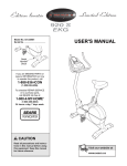
USER'S MANUAL
QUESTIONS?
If you have questions, or if there
are missing parts, we will guarantee complete satisfaction
through direct assistance from
our factory.
TO AVOID UNNECESSARY
DELAYS, PLEASE CALL DIRECT
TO OUR TOLL-FREE CUSTOMER
HOT LINE. The trained technicians on our customer hot line
will provide immediate assistance, free of charge to you.
CUSTOMER
HOT LINE:
1-888-825-2588
Mon.-Fri.,
6 a.m.-6 p.m. MST
CAUTION
Read all precautions and instructions in this manual before using
this equipment. Keep this manual
for future reference.
/isit our website at
www.nordictrack.com
new products, prizes,
fitness tips, and much more!
®
TABLE OF CONTENTS
IMPORTANT PRECAUTIONS
.............................................................
BEFORE YOU BEGIN ...................................................................
ASSEMBLY ...........................................................................
HOW TO USE THE ELLIPTICAL CROSSTRAINER
.............................................
MAINTENANCE AND TROUBLESHOOTING
.................................................
CONDITIONING GUIDELINES ............................................................
PART LIST ...........................................................................
EXPLODED DRAWING .................................................................
HOW TO ORDER REPLACEMENT PARTS ...........................................
LIMITED WARRANTY
...........................................................
2
3
4
5
8
20
21
22
23
Back Cover
Back Cover
IM PORTANT PRECAUTIONS
WARNING:
To reduce the risk of serious injury, read the following
important precau-
tions before using the elliptical crosstrainer.
Read all instructions in this manual before
12. The pulse sensor is not a medical device.
Various factors, including the user's movement, may affect the accuracy of heart rate
readings. The pulse sensor is intended only
as an exercise aid in determining heart rate
trends in general.
using the elliptical crosstrainer,
It is the responsibility of the owner to ensure
that all users of the elliptical crosstrainer
are adequately informed of all precautions.
3. The elliptical crosstrainer is intended for
in-home use only. Do not use the elliptical
crosstrainer in a commercial, rental, or institutional setting.
13. When you stop exercising, allow the pedals
to slowly come to a complete stop. The elliptical crosstrainer does not have a free
wheel; the pedals will continue to move until
the flywheel stops.
4. Place the elliptical crosstrainer on a level
surface, with a mat beneath it to protect the
floor or carpet. Keep the elliptical crosstrainer indoors, away from moisture and dust.
...............
the power cord immediately
after use and before cleaning the elliptical
crosstrainer.
Inspect and properly tighten all parts regulady. Replace any worn parts immediately,
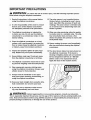
15. The decal shown below has been placed on
the elliptical crosstrainer. If the decal is
missing or illegible, please call our Customer
Service Department toll-free at 1-888-8252588 to order a free replacement decal.
Apply the decal in the location shown.
6. Keep children under age 12 and pets away
from the elliptical crosstrainer at all times.
7. The elliptical crosstrainer should not be used
by persons weighing more than 250 pounds.
8. Wear appropriate exercise clothing when
using the elliptical crosstrainer. Always wear
athletic shoes for foot protection.
9. Always hold the handlebar or the upper
body arms when mounting, dismounting,
using the elliptical crosstrainer.
or
10. Keep your back straight when using the elliptical crosstrainer; do not arch your back.
11. If you feel pain or dizziness while exercising, stop immediately and cool down.
WARN ING:
Before beginning this or any exercise program, consult your physician.
This is especially important for persons over the age of 35 or persons with pre-existing health problems. Read all instructions before using. SEARS assumes no responsibility for personal injury or
property damage sustained by or through the use of this product.
3
BEFORE YOU BEGIN
Congratulations for selecting the new NordicTrack _
CXT 980 elliptical crosstrainer. The CXT 980 is an
incredibly smooth exerciser that moves your feet in a
natural elliptical path, minimizing the impact on your
knees and ankles. And the unique CXT 980 features
adjustable resistance and incline to help you get the
most from your exercise. Welcome to a whole new
world of natural, elliptical-motion exercise from
NordicTrack.
tional questions, please call our Customer Service
Department toll-free at 1-888-825-2588, Monday
through Friday, 6 a.m. until 6 p.m. Mountain Time
(excluding holidays). To help us assist you, please
note the product model number and serial number
before calling. The model number is 831.298651. The
serial number can be found on a decal attached to the
elliptical crosstrainer (see the front cover of this manual for the location of the decal).
For your benefit, read this manual carefully before
you use the elliptical crosstrainer. If you have addi-
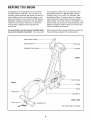
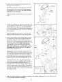
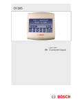
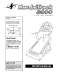
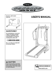
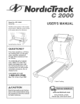
Before reading further, please familiarize yourself with
the parts that are labeled in the drawing below.
Water Bottle Holder*
Upper Body Arm
Bookrack
Handgrip Pulse Sensor
Console
FRONT
Incline Ramp
BACK
Wheel
Pedal
/
Pedal
Spring Arm
RIGHT SIDE
Power Cord --
g Foot
*No water bottle is included
4
ASSEMBLY
Assembly requires two people. Place all parts of the elliptical crosstrainer in a cleared area and remove the
packing materials. Do not dispose of the packing materials until assembly is completed. In addition to the two
included
wrench
allen wrenches, assembly requires a phillips
, a rubber mallet L...................
_
screwdrive_
and pliers
_==_,
an adjustable
_.
As you assemble the elliptical crosstrainer, use the drawings below to identify the small parts used in assembly.
The number in parenthesis below each drawing refers to the key number of the part, from the PART LIST on
page 22. The second number refers to the quantity used in assembly. Note: Some small parts may have been
pre-attached for shipping. If a part is not in the parts bag, check to see if it has been pre-assembled.
M8 x 19mm
Screw (30)-4
MIO x 25mm
Screw (102)-3
M10 x 43mm Screw (65)-4
M8 Split
Washer (58)-4
MIO Split
Washer (22)-11
M10 x 56mm Screw (60)-4
M8 Washer
(33)-4
MIO Washer
(63)-2
M10 x 33mm Carriage Bolt (61)-2
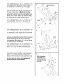
1. Identify the Rear Stabilizer (59), which has Leveling
Feet (14) threaded into it. Attach the Rear Stabilizer to
the Frame with the four M10 x 56mm Screws (60) and
four M10 Split Washers (22).
60
59
14
2. Attach the Front Stabilizer (90) to the Frame (1) with
the four M10 x 43mm Screws (65) and four M10 Split
Washers (22). Make sure that the Front Stabilizer is
turned so the Wheels (45) are not touching the
floor.
45
5
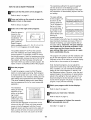
3. Slide an M8 Split Washer (58) and an M8 Washer (33)
onto an M8 x 19mm Screw (30). Tighten the Screw
into one end of an Incline Axle (29). Next, apply a
small amount of the included grease to the Incline Axle.
3ed Groove
Align the indicated tubes on the Incline Ramp (5) with
the tubes on the Frame (1). Make sure that the
Incline Ramp is turned so the V-shaped grooves
are on top. Insert the Incline Axle (29) into the Incline
Ramp and the Frame. Note: It may be helpful to tap
the Incline Axle with a rubber mallet to insert it.
Slide an M8 Split Washer (58) and an M8 Washer (33)
onto another M8 x 19mm Screw (30). Tighten the
Screw into the open end of the Incline Axle (29).
58
Grease
\
58
29
Tubes
33
4. Slide an M8 Split Washer (58) and an M8 Washer (33)
onto an M8 x 19mm Screw (30). Tighten the Screw
into one end of the other Incline Axle (29). Next, apply
a small amount of grease to the Incline Axle.
,\
Raise the Incline Ramp (5). Insert the Incline Axle (29)
through one side of the Incline Ramp, through a 56mm
Spacer (24), through the end of the motor screw,
through another 56mm Spacer (24), and then through
the other side of the Incline Ramp.
Slide an M8 Split Washer (58) and an M8 Washer (33)
onto another M8 x 19mm Screw (30). Tighten the
Screw into the open end of the Incline Axle (29).
Motor
Screw
Grease
5 _"-_
I
24
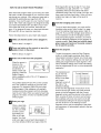
5. While another person holds the Upright (2) near the
Frame (1), connect the Wire Harness (85) to the
Extension Wire Harness (51). Next, attach the Upright
to the Frame with three M10 x 25mm Screws (102)
and three M10 Split Washers (22). Be careful to
avoid pinching the wire harnesses.
Make sure the
Wire Harnesses
(51, 85) do not
get pinched and
damaged during
this step.
22
102
22
22
6
7102
6. Connect the wire harness on the Console (87) to the
Extension Wire Harness (51).
Attach the Console (87) to the Upright (2) with the four
Console Screws (35) and the four Console Washers
(93) packaged with the Console. Be careful to avoid
pinching the wire harnesses.
Snap the bookrack onto the Console (87) in the location
shown.
.
93
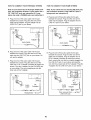
Identify the Left Pedal (41). Attach the Left Pedal to the
Left Spring Arm (3) with an M1O x 33mm Carriage Bolt
(61), an M10 Washer (63), and an Adjustment Knob
(77) as shown. Note: The Left Pedal can be attached in
any of five positions (see HOW TO ADJUST THE PEDALS on page 9).
Attach the Right Pedal (not shown) in the same way.
Make sure that both Pedals are in the same position.
\
_61
41
3
77
8. Apply a small amount of the included Teflon '_ lubricant
to a paper towel. Rub a thin film of the lubricant onto
the Chrome Tubes (21). Next, slide the Left Upper
Body Arm (7), which is marked with a sticker, onto the
left Chrome Tube. Slide the Right Upper Body Arm (75)
onto the right Chrome Tube. Make sure that the
Upper Body Arms are on the correct sides--the
upper ends should bend in the direction shown by
the arrows. Next, slide an Axle Cover (74) onto the
post on each Upper Body Arm.
Apply grease to the Arm Axle (19). Insert the Arm Axle
into the right Axle Cover (74) and the Right Upper Body
Arm (75). Next, insert the Arm Axle into the Upright (2)
until the left end of the Arm Axle is flush with the left
side of the Upright. Then, insert the Arm Axle into the
left Axle Cover (74) and the Left Upper Body Arm (7).
Center the Arm Axle (19). Using the included pedal
tool, tap two Push Nuts (15) about 1/8" onto each end
of the Arm Axle. Make sure that the Push Nuts are
turned as shown in the inset drawing. (Note: It may be
helpful if another person holds a block of wood against
one end of the Arm Axle while you tap Push Nuts onto
the other end.) Then, press an Axle Cap (34) onto each
end of the Arm Axle.
9. Make sure that all parts of the elliptical
be left over after assembly is completed.
crosstrainer are properly tightened.
7
Note: Some hardware may
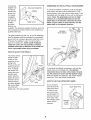
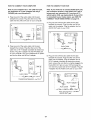
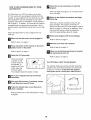
INSTALLING
THE RECEIVER FOR THE OPTIONAL CHEST PULSE SENSOR
If you purchase the optional chest pulse sensor (refer to
page 19), follow the steps below to install the receiver and
the Y-connector included with the chest pulse sensor.
1. Remove the four indicated screws from the back of the
Console (87). Lift the top of the Console. Be careful
not to disconnect any wires.
1
Screws
8
2. Peel the paper off the adhesive pad on the back of the
receiver (A). Orient the receiver exactly as shown, and
press it onto the Console (87) in the indicated location.
Connect the wire on the receiver (A) to the Y-connector
(B) as shown. Unplug the indicated console wire (C)
from the indicated jack (D), and plug the console wire
into the Y-connector. Then, plug the Y-connector into
the jack (D).
Refer to step 1 above. Reattach the top of the Console
(87) with the four screws. Make sure that no wires
are pinched.
Note: Any other wires that are included with the chest
pulse sensor may be discarded.
87
Cylinder
HOW TO USE THE ELLIPTICAL CROSSTRAINER
HOW TO PLUG IN THE POWER CORD
erly installed and grounded in accordance with all
local codes and ordinances. This product is for
use on a nominal 120-volt circuit. Important: The
elliptical crosstrainer is not compatible with GFCIequipped outlets,
This product
must be
grounded.
Grounded Outlet Box
If it should
malfunction
or break
down,
grounding
provides a
v.,-_Grounding
Pin
Grounded Outlet
path of least
resistance for
electric
current to reduce the risk of electric shock. This product is equipped with a cord having an equipmentgrounding conductor and a grounding plug. Plug the
power cord into an appropriate outlet that is prop-
DANGER:
Improper
connection
of the equipment-grounding conductc r can
result in an increased risk of electric shock,
Check with a qualified electrician or serviceman if you are in doubt as to whether the
product is properly grounded. Do not modify
the plug provided with the product--if it will
not fit the outlet, have a proper outlet
installed by a qualified electrician.
8
EXERCISING ON THE ELLIPTICAL CROSSTRAINER
A temporary
adapter may
be used to
connect the
power cord
to a 2-pole
receptacle
as shown at
the right if a
properly
grounded
outlet is not
Outlet Box
To mount the elliptical crosstrainer, hold the handgrip
pulse sensor and step onto the pedal that is in the
lowest position. Next, step onto the other pedal. Push
the pedals until they begin to move with a continuous
motion. Note: The pedal disks can turn in either
direction. It is recommended that you turn the
pedal disks in the direction shown by the arrow
below. To give variety to your exercise, turn the
pedal disks in the opposite direction.
Lug
Metal Screw
available. The temporary adapter should be used only
until a properly grounded outlet can be installed by a
qualified electrician.
Handgrip
The green-colored rigid ear, lug, or the like extending
from the adapter must be connected to a permanent
ground such as a properly grounded outlet box cover.
Whenever the adapter is used, it must be held in
place by a metal screw. Some 2-pole receptacle
outlet box covers are not grounded. Contact a
qualified electrician to determine if the outlet box
cover is grounded before using an adapter.
Pedal
Pedal Disk
HOW TO ADJUST THE PEDALS
The motion of the
pedals is determined by their
positions on the
spring arms.
There are five different pedal positions. To adjust
the pedals, first
loosen the knob
beneath each
pedal. Slide the
pedals forward or
backward to the
desired position,
and then retighten
the knobs. Make
sure that both
_ Pedal
To dismount the elliptical crosstrainer, wait until the
pedals come to a complete stop. The elliptical
crosstrainer does not have a free wheel; the pedals will continue to move until the flywheel stops.
When the pedals are stationary, step off the highest
pedal first. Then, step off the lowest pedal.
HOW TO USE THE UPPER BODY ARMS
Knob
As you exercise,
push and pull the
upper body arms
in order to work
your arms, back,
and shoulders. To
exercise only your
lower body, hold
the handgrip pulse
sensor as you
exercise.
pedals are in the same position.
Upper Body Arms
Handgrip_
Pulse
Sensor
9
/ / /1 I
/_/(_
CONSOLE DIA
ADJUSTYOURSPEED
MOTIVATIONAL
TRAINING
OMAO/_LASH/NG,_
_RA_._N_zo.
_,G._....................
'
/Tg
WARM-UP/COOL-DOWN
Note: If there is
a sheet of clear
plastic on the
face of the console, remove it.
_
_
FA%B URN
ZONES
...............................
• •
_ _
Trainma
'='
NDURANCE
Zone Bar
PERFORMANCE
t
10 °
15 °
20 °
SKI
25 °
CYCLE
30 °
CLIMB
s
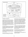
FEATURES OF THE CONSOLE
sonal trainer right in your home. Using the included
audio cable, you can connect the elliptical crosstrainer
to your home stereo, portable stereo, or computer and
play special iFIT.com CD programs (CDs are available
separately). IFIT.com CD programs automatically control the resistance of the elliptical crosstrainer and
prompt you to vary your pace as a personal trainer
coaches you through every step of your workout. Highenergy music provides added motivation. Each CD features two programs designed by certified personal
trainers.
The advanced console offers a selection of features
designed to make your workouts more enjoyable and
effective. When the manual mode of the console is
selected, the resistance of the elliptical crosstrainer
and the angle of the incline ramp can be changed with
a touch of a button. As you exercise, the console will
provide continuous exercise feedback. You can even
measure your heart rate using the handgrip pulse sensor. (For information about an optional chest pulse sensor, refer to page 19.)
In addition, you can connect the elliptical crosstrainer
to your VCR and TV and play iFIT.com video programs
(videocassettes are available separately). Video programs offer the same benefits as iFtT.com CD programs, but add the excitement of working out with a
class and an instructor.
The console also offers eight smart workout programs.
Each program automatically changes the resistance of
the elliptical crosstrainer and prompts you to increase
or decrease your pace as it guides you through an
effective workout.
In addition, the console features two heart rate workout programs that automatically change the resistance
of the elliptical crosstrainer and prompt you to vary
your pace to keep your heart rate near a target heart
rate as you exercise.
With the elliptical crosstrainer connected to your computer, you can also go to our new Web site at
www.iFIT.com and access audio programs and video
programs directly from the internet.
To purchase iFIT.com CDs and videocassettes,
toll-free 1-800-735-0768.
The console also features new iFIT.com interactive
technology. IFIT.com technology is like having a per-
10
call
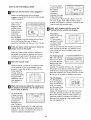
HOW TO USE THE MANUAL
B
To vary the affect
of your exercise on
the elliptical
crosstrainer,
increase or
decrease the angle
of the incline ramp
by pressing the Ramp Angle buttons. There are
five ramp angles. Note: After the Ramp Angle
buttons are pressed, it will take a moment for the
ramp to reach the selected angle.
MODE
Make sure that the power cord is plugged in.
Make sure that the power cord is properly
plugged in (see HOW TO PLUG IN THE POWER
CORD on page 8).
Note: When the
)URSPEED MOTIVATIONAL
TRAINING
Z(
power cord is
plugged in, the
elliptical crossc::_ SPEED
C::3 RAMP
trainer may automatically calibrate itself.
During calibra_RES_ST^NCE
T_ME
tion, the letters
CAL will appear in the left display and the indicators in the Training Zone bar will flash in
sequence. Calibration will last one to two minutes.
B
_
The matrix-When the manual
mode or the
iFIT.com mode is
selected, the matrix
will show a track
representing 1/4
mile. As you exercise, the indicators around the
track will flash to indicate your position on the
track. When you have completed a lap, a new
lap will begin.
ress any
button
console or move the
pedals
to turn
on on
the the
power.
When any button on the console is pressed or
the pedals are moved, the displays and various
indicators will light. Note: If the power cord was
just plugged in, the power will already be on.
D
The Training Zone
bar--The Training
Zone bar will show
your pace and the
approximate intensity level of your
exercise. For example, if three or four indicators in
the bar are lit, the bar shows that your pace is
ideal for fat burning. During smart programs and
heart rate programs, the Training Zone bar will also
prompt you to increase or decrease your pace.
Select the manual mode.
When the power is turned on, the manual mode
will be selected. If you have selected a smart
program, a heart rate program, or the iFIT.com
mode, select the
manual mode by
pressing the Select
000000
Program button
000000
repeatedly until a
000000
track appears in
000@@
the matrix.
B
atch your progress with the matrix, the
Training Zone bar, and the two displays.
The left display will
show the elapsed
_sLEE
L =_:_:A_.....
I I--I.I-- I--I i
i U.
0 i;
I
The left
display-lf|[
time,
_k_E_
_:iME
_ "::::1
level, the
yourresistance
speed,
I
and the angle of the
incline ramp. The
display will change from one number to the next
every few seconds, as shown by the indicators
around the display. When a smart program or a
heart rate program is selected, the display will
show the time remaining in the program rather
than the elapsed time.
egin
exercising
and adjust
of
the
elliptical
crosstrainer
andthe
the resistance
angle of the
incline ramp as desired.
As you exercise,
change the resistance of the elliptical crosstrainer by
pressing the
I
Resistance buttons. There are
ten resistance levels; level 10 is the most challenging. Note: After the Resistance buttons are
pressed, it will take a moment for the pedals to
reach the selected resistance level.
11
If there are
\
thin sheets of
plastic on the
metal contacts
_Contacts
on the handgrip pulse sensor, peel off
the plastic. To
measure your
heart rate,
place your hands on the contacts; your palms
must be resting on the contacts closest to you,
and your fingers must be touching the other contacts. Avoid moving your hands.
The right
display--The
right
display will show
the distance you
have pedaled and
the approximate
number of calories
you have burned. The display will change from
one number to the other every few seconds, as
shown by the indicators. The display will also
show your heart rate when the pulse sensor is
used.
If you stop exercising for several seconds, a tone
will sound and the console will pause.
When your pulse is
detected, the heart
rate indicator above
Note: The console can display speed and distance
in either miles or kilometers. To determine which
unit of measurement is selected,
hold down the Start
Program button for
three seconds. An
E for English miles
or an M for metric
kilometers will
uJsJ_
MOTIVATIONAL
ZONES
i'__t_ ...............................................
........._=f,_J,=_=_._,
I,T4UR,
_NOUR,_cr _"
coo -',ewrJ
SPEED
appear
in the
matrix. To
change
the unit of mea-
TRAINING
the right display will
light, dashes may
appear in the display, and then your
heart rate will be shown. For the most accurate
heart rate reading, continue holding the contacts
for about 15 seconds. Note: If your heart rate is
not shown, make sure that your hands are positioned as described. Be careful not to move your
hands excessively or to squeeze the metal contacts too tightly.
_
RAMP
_
HART
[
-! i_,1
__
..........
......
= ..............................
_rO_l,_C[
RATE
_
surement, press
the + button (this is the button that also selects
resistance level 10). While an E or an M appears
in the matrix, the left display will show the total
numbers of hours that the elliptical crosstrainer
has been used, and the right display will show the
total number of miles pedaled. When you are finished viewing this information, press the Start
Program button again.
r_
When you hold the pulse sensor, the right display
will show your heart rate for about 15 seconds. If
you continue to hold the pulse sensor, the display
will show your heart rate along with the distance
you have pedaled and the number of calories you
have burned.
B
Measure your heart rate if desired.
hen you are finished exercising,
will automatically turn off.
the console
If the console buttons are not pressed and the
pedals are not moved for a few minutes, the console will automatically turn off.
Note: If you wear the optional chest pulse sensor (see page 19) and hold the handgrip pulse
sensor at the same time, the console may not
display your heart rate accurately.
12
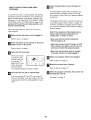
HOW TO USEA
_lMake
The resistance setting for the second segment
will then be shown in the flashing Current
Segment column and the resistance of the elliptical crosstrainer will automatically adjust to the second setting.
SMARTPROGRAM
sure that the power cord is plugged in.
Refer to step 1 on page 11.
B
The pace settings
a
for the program will
be shown by the
MOTIVATIONAL
TRAINING,_
ZONES
Training Zone bar.
The lit indicators in
....................................................................
the bar will show
your actual pace. If
b
an indicator to the
MOTIVATIONAL
TRAINING
ZONES
right of the lit indicators flashes (see
drawing a),
increase your pace.
If an indicator to the left of any lit indicator flashes
(see drawing b), decrease your pace. When no
indicator is flashing, your pace matches the current pace setting. Important: The pace settings
are intended only to provide motivation. Your
actual pace may be slower than the current
pace setting. Make sure to exercise at a pace
that is comfortable for you.
ress any
button
console or move the
pedals
to turn
on on
the the
power.
Refer to step 2 on page 11.
D
Select one of the eight smart programs.
When the power is
/
turned on, the
manual mode will
be selected. To
select a smart program, press the
Select Program
button repeatedly until a P-l, P-2, P-3, P-4, P-5,
P-6, P-7, or P-8 appears in the left display.
The profiles labeled P1 to P8 on the console
show the resistance and pace settings for the
smart programs. For example, profile P5 shows
that during program 5 both the resistance and the
pace will gradually increase during the first half of
the program, and then decrease during the last
half. Note: When you select a smart program, the
matrix will show a simplified profile of the program.
D
The program will continue until the resistance setting for the last segment is shown in the Current
Segment column of the matrix and the left display
shows that no time remains in the program.
Note: During the program, you can adjust the
angle of the incline ramp with the Ramp Angle buttons. In addition, you can override the resistance
setting for the current segment, if desired, with
the Resistance buttons. However, when the next
segment begins, the resistance will automatically
adjust to the setting for the next segment, tf you
stop exercising for several seconds, a tone will
sound and the program will pause. To restart the
program, simply resume exercising.
Start the program.
To start the program, press the Start Program
button or simply begin exercising. Each program
is divided into several one-, two-, three-, and fourminute segments. One resistance setting and one
pace setting are programmed for each segment.
(The same resistance setting and/or pace setting
may be programmed for two or more consecutive
segments.)
_
The resistance
Current Segment
setting for the first
segment will be
shown in the flashing Current
_°°°
ol
Segment column
of the matrix. The
resistance settings
for the next five segments will be shown in the
columns to the right. When only three seconds
remain in the first segment, both the Current
Segment column and the column to the right will
flash, a series of tones will sound, and all resistance settings will move one column to the left.
atch your progress with the two displays.
Refer to step 5 on page 11.
oo
r_
Measure your heart rate, if desired.
Refer to step 6 on page 12.
B
the program turn
is finished,
the console
willhen
automatically
off.
See step 7 on page 12.
13
Enter Age button and go to step 5. If you have
not entered your age, press the + or - button
repeatedly (these are the buttons that select
resistance levels 9 and 10) to enter your age, and
then press the Enter Age button. Once you have
entered your age, your age will be saved in
memory.
HOW TO USE A HEART RATE PROGRAM
Each heart rate program helps you to keep your heart
rate near a certain percentage of your maximum heart
rate during your workout. (Your maximum heart rate is
estimated by subtracting your age from 220. For
example, if you are 30 years old, your maximum heart
rate is 190.) Heart rate program 9 is designed to keep
your heart rate between 50% and 85% of your maximum heart rate while you exercise; heart rate program 10 is designed to keep your heart rate between
50% and 80% of your maximum heart rate.
B
To use a heart rate program, you must use the
handgrip pulse sensor (refer to step 6 on page
12) or the optional chest pulse sensor (refer to
page 19). If you use the handgrip pulse sensor, it
is not necessary to hold the handgrips continuously during the program. However, you should
hold the handgrips frequently for the program to
operate properly. Each time you hold the handgrips, keep your hands on the metal contacts
for at least 30 seconds.
Follow the steps below to use a heart rate program.
Make sure that the power cord is plugged in.
Refer to step 1 on page 11.
B
B
ress any
button
console or move the
pedals
to turn
on on
the the
power.
Select one of the heart rate programs.
When the power is
turned on, the
manual mode will
be selected. To
select a heart rate
program, press the
Select Program
button repeatedly until a P-9 or P-10 appears in
the left display.
The resistance setting for the first
segment will be
shown in the flash-
Current Segment
ing Current
Segment column of
the matrix. The
The profiles labeled P9 and P10 on the console
show the resistance settings for the heart rate
programs. For example, profile P9 shows that
during program 9 the resistance will gradually
increase during the program and then decrease
near the end. Note: When you select a heart rate
program, the matrix will show a simplified profile
of the program.
B
Start the program.
To start the program, press the Start Program
button or simply begin exercising. Each heart
rate program consists of twenty, one-minute segments. One resistance setting and one heart rate
setting are programmed for each segment. (The
same resistance setting and/or heart rate setting
may be programmed for two or more consecutive
segments.)
Refer to step 2 on page 11.
B
Hold the handgrip pulse sensor.
resistance settings
for the next five segments will be shown in the
columns to the right. When only three seconds
remain in the first segment, both the Current
Segment column and the column to the right will
flash, a series of tones will sound, and all resistance settings will move one column to the left.
The resistance setting for the second segment
will then be shown in the flashing Current
Segment column and the resistance of the elliptical crosstrainer will automatically adjust to the second setting.
Enter your age.
When a heart rate
program is select_]
c:::3 HEART RATE
ed, the word AGE
and the current
age setting will
ITIM_ _[_:
DISTANCE
flash in the right
display. You must
enter your age to use a heart rate program. If
you have already entered your age, press the
/,-,,- '--
14
As you exercise, the Training Zone bar will help
you to keep your heart rate near the heart rate
setting for the current segment. The lit indicators
in the bar will show
your actual pace.
When you hold the
handgrip pulse
sensor (or wear
the optional chest
pulse sensor), the
console will period-
HOW TO CONNECT YOUR CD PLAYER, VCR,
OR COMPUTER
a
To use iFIT.com CDs, the elliptical crosstrainer must
be connected to your portable CD player, portable
stereo, home stereo, or computer with CD player. See
pages 15 to 17 for connecting instructions. To use
iFIT.com videocassettes,
the elliptical crosstrainer
b
must
be
connected
to
your
VCR. See page 17 for con....................................................................................................................................
MOTIVATIONAL
TRAINING
ZONES
necting instructions. To use iFIT.com programs
directly from our Web site, the elliptical crosstrainer
____
must be connected to your home computer. See page
....................................................................................................................................
17 for connecting instructions.
MOTIVATIONAL
TRAINING
ZONES
ically compare
your heart rate to
the heart rate setting for the current
segment; if necessary, an indicator in the bar will then flash to
prompt you to increase or decrease your pace to
bring your heart rate closer to the current heart
rate setting. If an indicator to the right of the lit
indicators flashes (see drawing a above),
increase your pace. If an indicator to the left of
any lit indicator flashes (see drawing b), decrease
your pace. When no indicator is flashing, your
heart rate is near the current heart rate setting.
Important: The heart rate settings are intended only to provide motivation. Your actual
heart rate may be slower than the current
heart rate setting. Make sure to exercise at a
pace that is comfortable for you.
N _j
FAT
_URN
NDLJRANCL
_PF
HOW TO CONNECT YOUR PORTABLE CD PLAYER
Note: If your CD player has separate LINE OUT and
PHONES jacks, see instruction A below. If your CD
player has only one jack, see instruction B.
A. Plug one end of the audio cable into the jack
beneath the console. Plug the other end of the
cable into the LINE OUT jack on your CD player.
Plug your headphones into the PHONES jack.
A
The program will continue until the resistance setting for the last segment is shown in the Current
Segment column of the matrix and the left display
shows that no time remains in the program.
Audio
Cable
"
Note: During the program, you can adjust the angle
of the incline ramp with the Ramp Angle buttons. In
addition, you can manually override the resistance
setting for the current segment, if desired, with the
Resistance buttons. However, when the next segment begins, the resistance will automatically
adjust to the setting for the next segment. If you
stop exercising for six seconds or longer, a tone
will sound and the program will pause.
B
phones
_
Head-
B. Plug one end of the audio cable into the jack
beneath the console. Plug the other end of the
cable into a 1/8" Y-adapter (available at electronics
stores). Plug the Y-adapter into the PHONES jack
on your CD player. Plug your headphones into the
other side of the Y-adapter.
atch your progress with the two displays.
B--'_
Refer to step 5 on page 11.
r ..............
•
i PHONES(_!
..............
•
Audio
When
the program
is finished, the console will
automatically
turn off.
1/8"
Y-adapter.
See step 7 on page 12.
i___
Headphones _c3::>_
15
I'"
i
I_
U
HOW TO CONNECT YOUR PORTABLE STEREO
HOW TO CONNECT YOUR HOME STEREO
Note: If your stereo has an RCA-type AUDIO OUT
jack, see instruction A below. If your stereo has a
1/8" LINE OUT jack, see instruction
B. If your
stereo has only a PHONES jack, see instruction
C.
Note: If your stereo has an unused LINE OUT jack,
see instruction A below. If the LINE OUT jack is
being used, see instruction B.
A. Plug one end of the audio cable into the jack
beneath the console. Plug the other end of the
cable into the adapter. Plug the adapter into the
LINE OUT jack on your stereo.
A. Plug one end of the audio cable into the jack
beneath the console. Plug the other end of the
cable into the adapter. Plug the adapter into an
AUDIO OUT jack on your stereo.
°CD
° --
A_
°Amp |
i UNEOUT
(_ :=
i
Adapter_
Audio Cable
B. Plug one end of the audio cable into the jack
beneath the console. Plug the other end of the
cable into the LINE OUT jack on your stereo. Do
not use the adapter.
a.
C. Plug one end of the audio cable into the jack
beneath the console. Plug the other end of the
cable into a 1/8" Y-adapter (available at electronics
stores). Plug the Y-adapter into the PHONES jack
on your stereo. Plug your headphones into the
other side of the Y-adapter.
Plug one end of the audio cable into the jack
beneath the console. Plug the other end of the
cable into the adapter. Plug the adapter into an
RCA Y-adapter (available at electronics stores).
Next, remove the wire that is currently plugged into
the LINE OUT jack on your stereo and plug the
wire into the unused side of the Y-adapter. Plug the
Y-adapter into the LINE OUT jack on your stereo.
Audio
Cable
Wire removed from
LINE OUT jack
16
HOW TO CONNECT YOUR COMPUTER
HOW TO CONNECT YOUR VCR
Note: If your computer has a 1/8" LINE OUT jack,
see instruction A. If your computer has only a
PHONES jack, see instruction B.
Note: If your VCR has an unused AUDIO OUT jack,
see instruction A below. If the AUDIO OUT jack is
being used, see instruction B. If you have a TV
with a built-in VCR, see instruction B. If your VCR
is connected to your home stereo, see HOW TO
CONNECT YOUR HOME STEREO on page 16.
A. Plug one end of the audio cable into the jack
beneath the console. Plug the other end of the
cable into the LINE OUT jack on your computer.
A
A. Plug one end of the audio cable into the jack
beneath the console. Plug the other end of the
cable into the adapter. Plug the adapter into the
AUDIO OUT jack on your VCR.
m
A
)///
Audio
i
_
ooo
B. Plug one end of the audio cable into the jack
beneath the console. Plug the other end of the
cable into a 1/8" Y-adapter (available at electronics
stores). Plug the Y-adapter into the PHONES jack
on your computer. Plug your headphones or speakers into the other side of the Y-adapter.
a.
m
_@_@
==,
Audio Cable
-
................
Plug one end of the audio cable into the jack
beneath the console. Plug the other end of the
cable into the adapter. Plug the adapter into an
RCA Y-adapter (available at electronics stores).
Next, remove the wire that is currently plugged into
the AUDIO OUT jack on your VCR and plug the
wire into the unused side of the Y-adapter. Plug the
Y-adapter into the AUDIO OUT jack on your VCR.
1/8"
Y-adapter
Headphones/Speakers
ROA.......
a
i
Audio Cable
Adapter
/
Wire removed from
AUDIO OUT jack
17
HOW TO USE IFIT.COM CD AND VIDEO
PROGRAMS
_'_
A moment after the play button is pressed, your
personal trainer will begin guiding you through
your workout. Simply follow your personal trainer's
instructions.
To use iFIT.com CDs or videocassettes, the elliptical
crosstrainer must be connected to your portable CD
player, portable stereo, home stereo, computer with
CD player, or VCR. See HOW TO CONNECT YOUR
CD PLAYER, VCR, OR COMPUTER on page 15. To
purchase iFIT.com CDs and videocassettes, call
toll-free 1-800-735-0768.
The program will function in almost the same way
as a smart program (refer to step 4 on page 13).
However, an electronic "chirping" sound will alert
you when the resistance and/or the pace setting is
about to change.
Follow the steps below to use an iFIT.com CD or
video program.
Note: If the resistance of the elliptical crosstrainer and/or the pace setting does not
change when a "chirp" is heard:
Make sure that the power cord is plugged in.
B
Refer to step 1 on page 11.
• Make sure that the indicator beside the
iFIT.com button is lit.
ress any
button
console or move the
pedals
to turn
on on
the the
power.
• Adjust the volume of your CD player or VCR.
If the volume is too high or too low, the console may not detect the program signals.
Refer to step 2 on page 11.
D
• Make sure that the audio cable is properly
connected and that it is fully plugged in.
Select the iFIT.com mode.
When the console
is turned on, the
manual mode will
be selected. To
select the iFIT.com
mode, press the
iFIT.com button.
The indicator beside the button will light.
B
Press the play button on your CD player or
VCR.
r_
watch your progress with the two displays.
Refer to step 5 on page 11.
B
easure your heart rate, if desired.
Refer to step 6 on page 12.
Insert the iFIT.com CD or videocassette.
When the program is finished,
automatically turn off.
If you are using an iFIT.com CD, insert the CD
into your CD player. If you are using an iFtT.com
videocassette, insert the videocassette into your
VCR.
See step 7 on page 12.
18
the console will
HOW TO USE PROGRAMS DIRECTLY FROM
OUR WEB SITE
Our Web site at www.iFIT.com allows you to play
iFIT.com audio and video programs directly from the
internet. To use programs from our Web site, the elliptical crosstrainer must be connected to your home
computer. See HOW TO CONNECT YOUR COMPUTER on page 17. tn addition, you must have an internet
connection and an internet service provider. A list of
specific system requirements will be found on our Web
site.
Follow the steps below to use a program from our
Web site.
_lMake
B
Follow the on-line instructions to start the
program.
When you start the program, an on-screen countdown will begin.
_
eturn to the elliptical crosstrainer and begin
exercising.
When the on-screen countdown ends, the program will begin. The program will function in
almost the same way as a Smart program (refer to
step 4 on page 13). However, an electronic "chirping" sound will alert you when the resistance
and/or the pace setting is about to change.
D
sure that the power cord is plugged in.
Follow your progress with the two displays.
Refer to step 5 on page 11.
Refer to step 1 on page 11.
_lMeasure
B
ress any
button
console or move the
pedals
to turn
on on
the the
power.
Refer to step 2 on page 11.
D
Refer to step 6 on page 12.
_lWhen
you are finished
will automatically
turn exercising,
off.
the console
Select the iFIT.com mode.
Refer to step 7 on page 12.
When the console
is turned on, the
manual mode will
be selected. To
select the iFIT.com
mode, press the
iFIT.com button.
The indicator beside the button will light.
B
your heart rate if desired.
THE OPTIONAL
The optional chest pulse sensor provides hands-free
operation and continuously monitors your heart rate
during your workouts. To purchase the optional
chest pulse sensor, call toll-free 1-800-734-2377.
/
o to your computer and start an internet
connection.
_
if necessary, and go
totart
ouryour
Web Web
site browser,
at www.iFIT.com.
r_
Follow the desired links on our Web site to
select a program.
CHEST PULSE SENSOR
Read and follow the on-line instructions for using
a program.
19
/
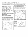
MAINTENANCE
AND TROUBLESHOOTING
Inspect and properly tighten all parts of the elliptical
crosstrainer regularly. Replace any worn parts immediately.
For smooth
operation of the
elliptical
crosstrainer, the
incline ramp
should be kept
clean. Using a
soft cloth and
mild detergent,
clean dust and
other residue
from the incline
Next, locate the Reed Switch (50). Turn the Flywheel
(37) until the Magnet (55) is aligned with the Reed
Switch. Loosen, but do not remove, the indicated
Screw (72). Slide the Reed Switch slightly closer to or
away from the Magnet. Retighten the Screw. Rock the
Flywheel forward and back just enough that the
Magnet passes the Reed Switch repeatedly. Repeat
until the console displays correct feedback. When the
Reed Switch is correctly adjusted, reattach the side
shields and the pedal disks.
"incline
___._
Ramp
ramp where the wheels make contact with it. Other
parts of the elliptical crosstrainer can also be cleaned
in this way. Keep liquids off the console. Never use
abrasives or solvents.
HOW TO ADJUST THE REED SWITCH
If the console does not display correct feedback, the
reed switch should be adjusted. To adjust the reed
switch, the Side Shields (47, 48) and the Pedal Disks
(40) must be removed. Remove the indicated Screws
(72, 88) from both Side Shields and Pedal Disks. Pull
the Pedal Disks out of the Side Shields. Lift the Side
Shields off the elliptical crosstrainer.
HOW TO LEVEL THE ELLIPTICAL
CROSSTRAINER
If the elliptical
crosstrainer
rocks slightly
during use,
turn one or
both of the
47
48\
leveling feet
under the rear
stabilizer until
the rocking
motion is eliminated.
72
2O
Leveling
Feet
CONDITIONING
GUIDELINES
During the first few minutes of exercise, your body
uses easily accessible carbohydrate calories for energy. Only after the first few minutes of exercise does
your body begin to use stored fat calories for energy.
If your goal is to burn fat, adjust the intensity of your
exercise until your heart rate is near the lowest number in your training zone as you exercise.
WARNING:
1. Before beginning this or any exercise program, consult your physician. This is especially important for persons over the age of
35 or persons with pre-existing health
problems.
For maximum fat burning, adjust the intensity of your
exercise until your heart rate is near the middle number in your training zone as you exercise.
2. The pulse sensor is not a medical device.
Various factors may affect the accuracy of
heart rate readings. The pulse sensor is
intended only as an exercise aid in determining heart rate trends in general.
Aerobic Exercise
If your goal is to strengthen your cardiovascular system, your exercise must be "aerobic." Aerobic exercise is activity that requires large amounts of oxygen
for prolonged periods of time. This increases the
demand on the heart to pump blood to the muscles,
and on the lungs to oxygenate the blood. For aerobic
exercise, adjust the intensity of your exercise until
your heart rate is near the highest number in your
training zone as you exercise.
The following guidelines will help you to plan your
exercise program. Remember that proper nutrition
and adequate rest are essential for successful results.
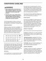
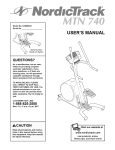
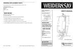
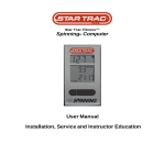
EXERCISE INTENSITY
Whether your goal is to burn fat or to strengthen your
cardiovascular system, the key to achieving the
desired results is to exercise with the proper intensity.
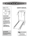
The proper intensity level can be found by using your
heart rate as a guide. The chart below shows recommended heart rates for fat burning, maximum fat
burning, and cardiovascular (aerobic) exercise.
165
155 145
140
130 125
115
_-_
145 138 130
125
118 110
103
_
125
120
115
110
105
95
90
20
30
40
50
60
70
80
WORKOUT GUIDELINES
Each workout should include the following three parts:
A warm-up, consisting of 5 to 10 minutes of stretching
and light exercise. A proper warm-up increases your
body temperature, heart rate, and circulation in preparation for exercise.
Training zone exercise, consisting of 20 to 30 minutes of exercising with your heart rate in your training
zone. (During the first few weeks of your exercise
program, do not keep your heart rate in your training
zone for longer than 20 minutes.)
A cool-down, with 5 to 10 minutes of stretching. This
will increase the flexibility of your muscles and will
help to prevent post-exercise problems.
To find the proper heart rate for you, first find your age
on the bottom line of the chart (ages are rounded off
to the nearest ten years). Next, find the three numbers
above your age. The three numbers are your "training
zone." The lower two numbers are recommended
heart rates for fat burning; the highest number is the
recommended heart rate for aerobic exercise.
EXERCISE FREQUENCY
To maintain or improve your condition, complete three
workouts each week, with at least one day of rest
between workouts. After a few months of regular exercise, you may complete up to five workouts each week
if desired. The key to success is to make exercise a
regular and enjoyable part of your everyday life.
Fat Burning
To burn fat effectively, you must exercise at a relatively low intensity level for a sustained period of time.
21
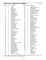
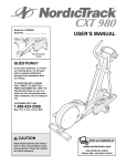
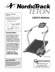
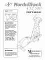
PART LISTmModel
Key No.
Qty.
1
2
3
4
5
6
7
8
9
10
11
12
13
14
15
16
17
18
19
20
21
22
23
24
25
26
27
28
29
30
31
32
33
34
35
36
37
38
39
40
41
42
43
44
45
46
47
48
49
50
51
52
53
54
55
56
1
1
1
1
1
2
1
1
2
1
1
1
1
2
4
1
2
2
1
2
2
11
6
2
2
2
2
1
2
4
10
4
4
2
4
1
1
2
1
2
1
1
12
2
2
2
1
1
2
1
1
1
2
1
1
1
No. 831.298651
Description
R0902A
Key No.
Qty.
57
58
59
60
61
62
63
64
65
66
67
68
69
70
71
72
73
74
75
76
77
78
79
80
81
82
83
84
85
86
87
88
89
90
91
92
93
94
95
96
97
98
99
100
101
102
103
104
105
106
107
#
#
#
#
#
1
4
1
4
2
2
2
2
4
1
4
1
1
1
3
8
11
2
1
4
2
2
2
4
1
1
2
1
1
12
1
4
3
1
1
12
4
1
1
1
4
1
1
1
2
3
1
3
1
1
1
1
1
1
2
1
Frame
Upright
Left Spring Arm
Right Spring Arm
Incline Ramp
Crank Arm
Left Upper Body Arm
Large Pulley
Frame Bearing
Plastic Crank Spacer
Flat Delrin Washer
Idler Bracket
Power Cord
Leveling Foot
Push Nut
M10 x 25mm Flat Head Bolt
M8.5 Flat Washer
Foam Grip
Arm Axle
Plastic Arm Sleeve
Chrome Tube
M10 Split Washer
Arm Bushing
56mm Spacer
Frame Endcap
M10 Nylon Locknut
M10 Union Bolt Set
Belt
Incline Axle
M8 x 19mm Screw
Incline Bushing
Incline Ramp Cap
M8 Washer
Pivot Axle Cap
Console Screw
Spring
Flywheel
Flywheel Bearing
Flywheel Axle
Pedal Disk
Left Pedal
Right Pedal
M6 x 33mm Flat Head Screw
Incline Wheel
Stabilizer Wheel
M8 Union Bolt Set
Left Side Shield
Right Side Shield
M5 x 6mm Screw
Reed Switch/Wire
Extension Wire Harness
Reed Switch Bracket
Spring Bracket
Reed Switch Clamp
Magnet
Left Rear Spring Bracket
Description
Right Rear Spring Bracket
M8 Split Washer
Rear Stabilizer
M10 x 56mm Screw
M10 x 33mm Carriage Bolt
Front Stabilizer Endcap
M10 Washer
Rear Stabilizer Endcap
M10 x 43mm Screw
"J" Bolt
Spring Bracket Bushing
Eyebolt
"C" Magnet
Adjustment Bracket
M4 x 63.5mm Screw
M4 x 16mm Screw
M5 x 16mm Screw
Axle Cover
Right Upper Body Arm
Pedal Bushing
Adjustment Knob
Snap Ring
Spring Spacer
M8 Nylon Locknut
Adjustment Cable Assembly
Resistance Motor
Flange Screw
M6 x 38mm Bolt
Wire Harness
M6 Nylon Locknut
Console
M5 x 25mm Screw
Stop Nut
Front Stabilizer
Side Shield Support
M6 Washer
Console Washer
Incline Motor
Reed Switch Lock
Incline Reed Switch
Tree Fastener
Left Incline Shield
Right Incline Shield
Incline Bolt
Incline Spacer
M10 x 25mm Screw
Zip Tie
#8 x 3/8" Screw
Wiring Board
Junction Box/Cover
Grommet
Grease
Teflon ®Lubricant
Push Nut Tool
Allen Wrench
User's Manual
Note: # indicates a non-illustrated part. Specifications are subject to change without notice. See the back cover
of this manual for information about ordering replacement parts.
22
<
cq
o
o_
o
88
n-
34
75"
15
Le)
72
73
23
"86
89 70
(ej
4"
10(
96
"0
3 78
_,)
¢",,I
32
76
57
79_5833
72-*.
104
L
8o_;,"
_z
58:
-72
103
-[¢1_10_
25 105_7
"'"
16
46
90
6O
83
62
13
60
¢
51
64
62
79
88
59.
14
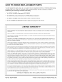
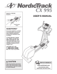
HOW TO ORDER REPLACEMENT
PARTS
To order replacement parts, simply call our Customer Service Department toll-free at 1-888-825-2588, Monday
through Friday, 6 a.m. until 6 p.m. Mountain Time (excluding holidays). To help us assist you, please be
prepared to give the following information when calling:
• The MODEL NUMBER of the product (831.298651)
• The NAME of the product (NordicTrack '_ CXT 980 elliptical crosstrainer)
• The SERIAL NUMBER of the product (see the front cover of this manual)
• The KEY NUMBER and DESCRIPTION
of the part(s) from page 22 of this manual.
LI MITED WARRANTY
WHAT IS COVERED--The
workmanship.
entire NordicTrack2
WHO IS COVERED--The
original purchaser or any person receiving the Product as a gift from the original purchaser.
HOW LONG IS IT COVERED--ICON
Labor is covered for one year.
elliptical crosstrainer
("Product") is warranted to be free of all defects in material and
Health & Fitness, Inc. ("ICON"), warrants the product for one year after the date of purchase.
WHAT WE DO TO CORRECT COVERED DEFECTS--We will ship to you, without charge, any replacement part or component, providing the repairs are authorized by ICON first and are performed by an ICON trained and authorized service provider, or, at our
option, we will replace the Product.
WHAT IS NOT COVERED--Any
failures or damage caused by unauthorized service, misuse, accident, negligence, improper assembly or installation, alterations, modifications without our written authorization or by failure on your part to use, operate, and maintain
as set out in your User's Manual ("Manuar').
WHAT YOU MUST DO--Always
retain proof of purchase, such as your bill of sale; store, operate, and maintain the Product as specified in the Manual; notify our Customer Service Department of any defect within 10 days after discovery of the defect; as instructed, return any defected part for replacement or, if necessary, the entire product, for repair.
USER'S MANUAL--It
periodic maintenance
is VERY IMPORTANT THAT YOU READ THE MANUAL before operating the Product. Remember to do the
requirements specified in the Manual to assure proper operation and your continued satisfaction.
HOW TO GET PARTS AND SERVICE--Simply
call our Customer Service Department at 1-888-825-2588 and tell them your name
and address and the serial number of your Product. They will tell you how to get a part replaced, or if necessary, arrange for service
where your Product is located or advise you how to ship the Product for service. Before shipping, always obtain a Return
Authorization Number (RA No.) from our Customer Service Department; securely pack your Product (save the original shipping carton if possible); put the RA No. on the outside of the carton and insure the product. Include a letter explaining the product or problem and a copy of your proof of purchase if you believe the service is covered by warranty.
ICON is not responsible or liable for indirect, special or consequential damages arising out of or in connection with the use or performance of the product or damages with respect to any economic loss, loss of property, loss of revenues or profits, loss of enjoyment or use, costs of removal, installation or other consequential damages of whatsoever nature. Some states do not allow the exclusion or limitation of incidental or consequential damages. Accordingly, the above limitation may not apply to you.
The warranty extended hereunder is in lieu of any and all other warranties and any implied warranties of merchantability or fitness
for a particular purpose is limited in its scope and duration to the terms set forth herein. Some states do not allow limitations on how
long an implied warranty lasts. Accordingly, the above limitation may not apply to you.
No one is authorized to change, modify or extend the terms of this limited warranty. This warranty gives you specific legal rights and
you may have other rights which vary from state to state.
ICON HEALTH & FITNESS, INC., 1500 S. 1000 W., LOGAN, UT 84321-9813
Part No. 185204 R0902A
Printed in China © 2002 ICON Health & Fitness, Inc.