1
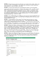
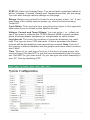
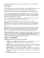
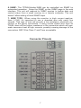
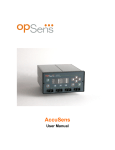
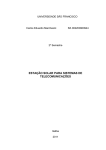
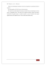
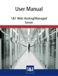
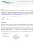
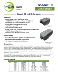
TPDIN-Monitor-WEB
Web Based Monitor and
Control
▫
Remote Power Stations
▫
Backup Power Systems
▫
Solar Systems
▫
Wind Powered Systems
▫
Industrial Sense & Control
▫
Process Automation
Congratulations! on your purchase of the TPDIN-MonitorWEB PowerSens™ System Monitor. Please take a moment to
review this Qwik Install Guide before installation.
Recommended Tools and Supplies: Small Flat Blade Screwdriver, 35mm x 7.5mm DIN Rail
Qwik Install
STEP 0: The TPDIN-Monitor-WEB can be used to monitor Qty 4 1V80V Voltages, 4 Currents ( Qty 2 +/- 10A and Qty 2 +20A) and two temperatures (1 internal and 1 external). There are 4 10A relays that can be
used to control power to 4 devices. Two of those relays can be automatically set based on a temperature or voltage value. Two can be operated automatically based on a ping watchdog or time control.
STEP 1: Install the TPDIN-Monitor-WEB to a suitable DIN rail mount.
STEP 2: Connect the voltages to be monitored to the V1—V4 voltage
ports. The green connector needs to be removed to be able to access
the wire terminal screws. The green connectors are numbered 1-7 and
should be re-installed back in their proper position. Voltages between 1
and 80volts DC can be monitored.
STEP 3: Connect the currents to be monitored to the I1-I4 current ports.
I1 and I2 can read currents from 0.1 to 20A. I3 and I4 can read positive
or negative currents to +/-10A. These can be used to measure current
flowing into and out of a battery to see if the battery is charging or discharging. The green connectors may need to be removed to be able to
access the wire terminal screws. The green connectors are numbered
1-7 and should be re-installed back in their proper position.
STEP 4: Connect any power to devices you want to be under relay control to the CHI—CH4 relays. The relays are normally closed relays so
activating the relay will open the relay.
STEP 5: Connect the External Temperature sensor to the included
green wire terminal connector. Connect the wires to IN– and IN+ terminals. Plug the wire terminal connector to the “Temp.” connector location. Locate the external temperature sensor where you want to measure external temperatures. You can extend the wire lengths if desired
by soldering additional wires to the existing wires. You can measure
temperatures from –40C to +125C
STEP 6: The TPDIN-Monitor-WEB can be powered with 10-58VDC thru
wire terminal connector #7 or via 802.3af or Passive 48V POE thru the
RJ45 POE/DATA port.
STEP 7: Download the Discovery Tool from http://tyconpower.com/
Support/support_TPDIN-Monitor-WEB.htm . The TPDIN-Monitor-WEB
ships with IP addressing by DHCP enabled. The discovery tool will find
the IP address of the device so you can access the web control panel. If
not connected to a DHCP server the default IP address is 192.168.1.2
STEP 8: Open the Web control panel of the unit by using the discovery
tool or typing the units known IP address into a browser. The unit will
serve up the Monitor web page. The monitor page is where all the voltage, current, temperature and relay status can be seen. Relays can
also be controlled manually from this page. There is a cycle button by
the relays if you want to automatically cycle a relay from on to off and
back. The cycle delay is specified on the SYSTEM page.
STEP 9: Open the Network Page. Here you can set a static IP Address.
You can also set access security by entering a user name and password (10 characters max). You can also set a unique Host Name to
identify the Monitor.
2
STEP 10: Open the System Page. You should add meaningful labels to
all the Voltages, Currents, Relays and Temperatures that you are using.
You can also change various settings on this page.
Relays: Relays are normally closed to save power when “on”. If you
want them to be initially open at power-up, check the box that says
“Initial Off”.
Cycle Delay: This controls how long the relay stays in the opposite
state when cycle is clicked on the Monitor Screen.
Voltage, Current and Temp Offsets: You can enter + or –offset values if you want to calibrate the TPDIN-Monitor-WEB to match another
piece of measurement equipment or compensate for cable losses.
Log Interval: This sets the number of seconds between log readings. The log can store 1300 data sets. If this is exceeded the oldest
records will be discarded as new records are entered. Note: If set to 0
the logging of data is disabled and the graphs and some other functions
won’t work.
Time: There is no real time clock so if the device loses power the
clock will reset. Enable NTP to get the time automatically from the internet. Set GMT for your time zone. Or you can sync the clock manually to
your PC Time by disabling NTP.
3
STEP 11: Open the Control Page. This is where you can set the relay
Ping Control or Time and Temperature or voltage controls. You can set
up the EMAIL server and set various email triggers.
Relays 1 and 2:
Time Control: Set the On time and Off time in 24hr format. Note:
Time control overrides Ping Control and Manual control.
Ping Control: Set the IP Address to ping. Set the ping frequency
(Every). Setting the frequency to zero disables the ping. Set the number
of consecutive Fails before the relay will cycle. Set the Wait so that the
system will wait before pinging again. This is useful to allow the unit that
you are pinging to fully reboot after a power cycle. Example: if you set
the unit to ping every 60 seconds and you have fail set to 2, it will take
approx. 2 minutes before it would see two consecutive failures and then
cycle the relay.
Relays 3 and 4:
Temperature Control: Relay 3 can be controlled by the Internal
Temperature and Relay 4 can be controlled by the External temperature probe. Make sure ON temperature is lower than OFF temperature
setting.
Typical Application:
Fan Control: Set ON to 50; Set OFF to 100
Heater Control: Set ON to –40; Set OFF to 20
Voltage Control: Set the relay turn on and turn off voltages. Relay
4
will change state when voltage goes outside the range. Temperature
set takes priority.
Email Alerts:
Set the Email server: ie; smtp.1and1.com Note: GMAIL accounts won’t
work because they require SSL security when sending emails.
Set the email account user name and password. Leave user name
blank to force no authentication. Password field is 10 characters max.
Check the “Use Username as From Field” checkbox (recommended)
to have the emails sent from the username which is usually an email
address. If not checked, the emails will be sent from the email address
entered in the first MAIL To: field.
Enter the destination email addresses in the Mail To: fields. They can
be the same or different depending on your needs.
Select the parameter trigger from the dropdown box on the left.
Periodical: This will send an email of the present readings periodically based on the number of minutes entered into the Lower/minutes
box. Caution: if you leave set at 0 it will send an email every two seconds
Relay 1-4: These will send an email any time the state of the relay
changes due to some automatic relay control like Ping, Time or Temperature. It won’t send an email when the relay is manually operated.
Relay 1-4 doesn’t require any lower or upper settings. Leave at 0.
Volt Amp and Temp: Just set Lower and Upper values and the system will send an email anytime the reading is outside the set range. The
frequency of emails is set by the Analog Values Mail Delay time. If the
delay time is set too low you will receive a flood of emails whenever one
of your set parameters fall outside the set range.
TECH CORNER
Additional Information you may find useful
1.
FUSE: The TPDIN-Monitor-WEB has an internal 2A fuse. If the
TPDIN-Monitor-WEB doesn’t power up, check the fuse.
2.
LIMITS: Don’t exceed 80V on the voltage inputs or 20A on the
current inputs or 10A on the relays or the unit could be damaged.
This kind of damage isn’t covered under warranty.
3.
MOISTURE: The TPDIN-Monitor-WEB is designed to be used indoors or outdoors in a weatherproof enclosure. Avoid getting the
TPDIN-Monitor-WEB wet. This kind of damage isn’t covered under
warranty.
4. BATTERY STATUS: If measuring voltage of battery systems
5
typical state of charge readings are as follows. These readings are
without any load on the battery. For max battery life don’t discharge
under 50%:
State Of Charge
Sealed or Flooded
Lead Acid
GEL Battery
AGM Battery
100%
12.7+Volts
12.9+Volts
12.8+Volts
75%
12.4 Volts
12.7 Volts
12.6 Volts
50%
12.2 Volts
12.4 Volts
12.3 Volts
25%
12.0 Volts
12.0 Volts
12.0 Volts
10%
11.8 Volts
11.8 Volts
11.8 Volts
5. Operating Power: The TPDIN-Monitor-WEB has extremely low operating power, typically less than 3W. The relays are normally closed
type so in typical operation they don’t take any power until they are energized. If the relays are turned on to hold them open, the power usage
will increase.
Specifications
Voltage Meas (DC)
Voltage Meas Accuracy
Current Meas (DC)
Current Meas Accuracy
Temperature Meas
Temp Meas Type
Temp Meas Accuracy
Relays (Normally
Closed Type)
Relay Control
Power Requirements
Accessibility
Data-Logger
Connections
Wire Size
Mounting
Operating Temperature
Humidity (RH)
Dimensions (LxWxH)
Weight
V1, V2, V3, V4 = 1-80VDC
+/- 0.1V
I1, I2 = 0.1A to 20A
I3, I4 = +/-10A
+/- 0.1A
T1,T2 = -40C to 125C
T1 = Embedded, T2 = External Sensor (included)
+/- 1 degC
R1, R2, R3, R4 = 10A DC
R1, R2 = Manual or Ping or Time Control
R3, R4 = Manual or Temperature Control
10-58VDC Wire Terminal or 802.3af Class 0 POE,
3W Typ
Via Web Browser and SNMP
FIFO, Max 1300 data sets, Program log interval
Removable Wire Terminal
12AWG Max
DIN Rail
-40C to +75C (-40F to 167F)
0% - 90%
125 x 102 x 46mm (4.9” x 4” x 1.8”)
410g (14.5 oz)
6
6. SNMP: The TPDIN-Monitor-WEB can be controlled via SNMP for
automated operation. Setup the SNMP on the SNMP page in the web
interface. The unit will respond to SNMP queries to gather data and
control relays from a script running on a remote computer. The unit
doesn’t allow setting of local SNMP traps.
7. WIRE TYPE: When using the monitor in high current applications (>10A), it’s important to use a stranded wire with many fine
strands. This type of wire will provide a low resistance electrical connection to the green connectors. If using course strand wire such as
THHN, there will be higher resistance in the connection which will generate excessive heat at high currents, possibly causing damage to the
connectors. NEC Wire Class C and D are acceptable.
Connector Pinouts
7
Limited Warranty
The TPDIN-Monitor-WEB products are supplied with a limited 24 month
warranty which covers material and workmanship defects. This warranty does not cover the following:
▫ Parts requiring replacement due to improper installation, misuse,
poor site conditions, faulty power, etc.
▫ Lightning or weather damage.
▫ Physical damage to the external & internal parts.
▫ Products that have been altered, or defaced.
▫ Products that have been subjected to voltages or currents greater
than the published ratings.
▫ Water damage for units that were not mounted according to user
manual.
▫ Usage other than in accordance with instructions and the normal
intended use.
Typical Application
8000032 Rev 6 TPDIN-Monitor-WEB Qwik Install Guide
8