1
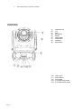
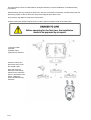
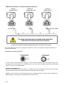
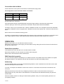
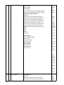
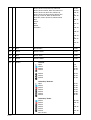
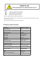
Tel: 253-395-9500 Fax: 253-395-9494 6403 South 208th Street, Kent, WA 98032 KEEP THIS MANUAL FOR FUTURE NEEDS 1 of 20 Every person involved with the installation, operation and maintenance of this device needs to ● be qualified ● follow the instructions of this manual ● consider this manual to be part of the total product ● keep this manual for the entire service life of the product Pass this manual on to every further owner or user of the product. Download the latest version of the user manual from the OmniSistem website. For your own safety, please read this user manual carefully before you initially start the product. INTRODUCTION Thank you for choosing an OmniSistem product. OmniSistem is a wholesaler of a large variety of lighting, sound, truss, and effects. Since 1986, we have been providing quality and affordable lighting products to North America. We are confident that our excellent products will meet your expectations. Included in this box you will find: 1. 2. 3. 4. 5. OnyxPro 40 User Manual Omega Holder with QuickLock Fastener Power Supply Cable Safety Cable SAFETY INSTRUCTIONS This device left our facility after a thorough QC check. In order to maintain excellent condition and to ensure a safe operation, it is absolutely necessary for the user to follow the safety instructions and warnings detailed in this user manual. Important: Damages caused by the disregard of this user manual are not subject to warranty. The dealer will not accept liability for any resulting defects or problems. 2 of 20 (Safety Instructions Continued) ● Minimum distance from flammable materials to all surfaces of the unit is 0.3m (11.81”). ● If the device has been exposed to drastic temperature fluctuation (e.g. after transportation), do not switch it on immediately. The arising condensation water might damage your device. Leave the device switched off until it has reached room temperature. ● Please make sure that there are no obvious transport damages. Should you notice any damages on the A/C connection cable or on the casing, do not take the device into operation and immediately consult your local dealer. ● This device falls under Protection Class I. The power plug must only be plugged into a Protection Class I outlet. The voltage and frequency must exactly be the same as stated on the device. Wrong voltages or power outlets can lead to the destruction of the device and to mortal electrical shock. ● Always plug in the power plug last. The power plug must always be inserted without excessive force. Make sure that the plug is tightly connected with the outlet. ● Never let the power cord come into contact with other cables! Handle the power cord and all connections with the mains with caution! Never touch them with wet hands, as this could lead to mortal electrical shock. ● Never modify, bend, strain mechanically, put pressure on, pull or heat up the power cord. Never operate next to sources of heat or cold. Disregarding this can lead to power cord damages, fire or mortal electrical shock. ● The cable insert or the female part in the device must never be strained. There must always be sufficient cable to the device. Otherwise, the cable may be damaged which may lead to mortal damage. ● Make sure that the power cord is never crimped or damaged by sharp edges. Check the device and the power cord from time to time. ● Do not connect more than 8 units together in a single power chain. ● If extension cords are used, make sure that the core diameter is sufficient for the required power consumption of the device. All warnings concerning the power cords are also valid for possible extension cords. ● Always disconnect from the power source, when the device is not in use or before cleaning it. Only handle the power cord by the plug. Never pull out the plug by tugging the power cord. Otherwise, the cable or plug can be damaged leading to mortal electrical shock. If the power plug or the power switch is not accessible, the device must be disconnected via the mains. ● If the power plug or the device is dusty, the device must be taken out of operation, disconnected and then be cleaned with a dry cloth. Dust can reduce the insulation which may lead to mortal electrical shock. More severe dirt in and at the device should only be removed by a specialist. ● There must never enter any liquid into power outlets, extension cords or any holes in the housing of the device. If you believe even a minimal amount of liquid may have entered the device, it must immediately be disconnected. This is also valid, if the device was exposed to high humidity. Also if the device is still running, the device must be checked by a specialist if the liquid has reduced any insulation. Reduced insulation can cause mortal electrical shock. ● There must never be any objects entering into the device. This is especially valid for metal parts. If any metal parts like staples or coarse metal chips enter into the device, the device must be taken out of operation and disconnected immediately. Malfunction or short-circuits caused by metal parts may cause mortal injuries. 3 of 20 Keep away children and amateurs! Never leave this device running unattended. OPERATING PROCEDURES This device is a moving head light for creating decorative effects. This product is only allowed to be operated with an alternating voltage of 100240V, 50/60 Hz and was designed for indoor use only. This device is designed for professional use, e.g. on stages, in clubs, bars, theatres, etc. Lighting effects are not designed for permanent operation. Consistent operation breaks will ensure that the device will serve you for a long time without defects. Do not shake the device. Avoid brute force when installing or operating the device. Never lift the fixture by holding it at the projector head, as the mechanics may be damaged. Always hold the fixture at the transport handles. When choosing the installation spot, please make sure that the device is not exposed to extreme heat, moisture or dust. There should not be any cables lying around. Please make sure that the unit cannot be touched or bumped. This device must never be operated or stockpiled in surroundings where water splash, rain, moisture or fog may harm the device. Moisture or very high humidity can reduce the insulation and lead to mortal electrical shocks. When using smoke machines, make sure that the device is never exposed to the direct smoke jet and is installed in a distance of 0.5 meters between smoke machine and device. The room must only be saturated with an amount of smoke that the visibility will always be more than 10 meters. The ambient temperature must always be between 15°C and +45°C. Keep away from direct heat (particularly in cars) and heaters. The relative humidity must not exceed 50% with an ambient temperature of 45° C. This device must only be operated in an altitude between 20 and 2000 m over sea level. Never use the device during thunderstorms. Overvoltage could destroy the device. Always disconnect the device during thunderstorms. This symbol determines the minimum distance from lighted objects. The minimum distance between light output and the illuminated surface must be more than this value. The housing must never touch surrounding surfaces or objects. Make sure that the area below the installation place is clear when rigging, derigging or servicing the fixture. For overhead use (mounting height >100 cm), always fix the fixture with an appropriate safety cable. Fix the safety cable at the correct fixation points only. The safety cable must never be fixed at the transport handles! Only operate the fixture after having checked that the housing is firmly closed and all screws are tightly fastened. The maximum ambient temperature Ta = 45°C must never be exceeded. Operate the device only after having become familiarized with its functions. Do not permit operation by persons not qualified for operating the device. Most damages are the result of unprofessional operation! 4 of 20 Please use the original packaging if the device is to be transported. Please consider that unauthorized modifications on the device are forbidden due to safety reasons and will void your warranty. Never remove the serial barcode from the device as this would void the warranty. If this device will be operated in any way different to the one described in this manual, the product may suffer damages and the guarantee becomes void. Furthermore, any other operation may lead to dangers like short circuit, burns, electric shock, crashing, etc. PRODUCT FEATURES & SPECIFICATIONS Light ● ● ● ● ● ● Light source: 40W RGBW LED Lamp life: 60,000 hours Luminous Flux: 4500 lumen, 1788 lux @ 3m Control: Remote on/off via DMX Ballast: switching mode power supply Beam angle: 12° X/Y ● ● ● ● Pan: 630° (4.0 sec) or 540° (3.58 sec), Tilt: 265° (2.8 sec) 16bit resolution Auto repositioning 3phase motor for fast and quiet movement ● ● RGBW LEDs for colorchanging saturated colors Two virtual color wheels for color bounce effect ● ● ● ● Outside ¢23mm, inside ¢18mm 6+ open, custom interchangeable position for rotating gobo wheel Real indexable and gobo shaking Distinctive gobo animation effect Colors Gobos Features ● ● ● ● ● ● ● ● ● ● ● ● DMX channels: 16/18 RGBW LED with two virtual color wheels Rotating gobo wheel: 6+1 gobos Manual focus Full range 0100% dimmer Various strobe Rotating 5facet prism RDM function to change DMX address, display flip, X/Y reverse, and more Software upgrade via DMX Hibernation when lost DMX for preset time Indicate temperature info of base, arm and lamp Fan speed auto change according to temperature Display ● ● ● ● 2.4 inch LCD display with English, Spanish, French, and Chinese menu Autolock Flip Backup communicating IC ● ● Max power consumption: 85W Power supply: Electronic autoranging Power 5 of 20 ● Input voltage range: 100–240V, 5060Hz OVERVIEW (1) Objective Lens (2) Arm (3) Base (4) Microphone (5) Display (6) Mode Button (7) Down Button (8) Up Button (9) Enter Button (10) (11) (12) (13) (14) 6 of 20 Power Input Power Output Fuse Holder 3Pin DMX Input Socket 3Pin DMX Output Socket INSTALLATION Inserting/Exchanging Gobos If you wish to use other gobos, or if gobos are to be exchanged, please follow the instructions below: Remove the fixation ring with an appropriate tool. Remove the gobo and insert the new gobo. Press the fixation ring together and insert it in front of the gobo. Rigging The installation of the projector has to be built and constructed in a way that it can hold 10 times the weight for 1 hour without any harming deformation. The installation must always be secured with a secondary safety attachment, e.g. an appropriate catch net. This secondary safety attachment must be constructed in a way that no part of the installation can fall down if the main attachment fails. When rigging, derigging or servicing the fixture staying in the area below the installation place, on bridges, under high working places and other endangered areas is forbidden. The operator needs to make sure that safetyrelated and machine technical installations are approved by an expert before taking into operation for the first time and after changes before taking into operation another time. The operator needs to make sure that safetyrelated and machine technical installations are approved by an expert after every four years in the course of an acceptance test. The operator needs to make sure that safetyrelated and machine technical installations are approved by a skilled person once a year. 7 of 20 Procedure: The projector should be installed outside areas where persons may walk by or be seated. IMPORTANT! OVERHEAD RIGGING REQUIRES EXTENSIVE EXPERIENCE, including (but not limited to) calculating working load limits, installation material being used, and periodic safety inspection of all installation material and the projector. If you lack these qualifications, do not attempt the installation yourself, but instead use a professional structural rigger. Improper installation can result in bodily injury and/or damage to property. The projector needs to be installed out of reach of people. If the projector shall be lowered from the ceiling or high joists, professional trussing systems need to be used. The projector must never be fixed swinging freely in the room. Caution: Projectors may cause severe injuries when crashing down! If you have doubts concerning the safety of a possible installation, do NOT install the projector! Before rigging make sure that the installation area can hold a minimum point load of 10 times the projector's weight. The unit can be placed directly on the stage floor or rigged in any orientation on a truss without altering its operation characteristics (see the drawing). The fixture base enables mounting in two ways. For overhead use (mounting height >100cm), always install an appropriate safety bond. Please note: for overhead rigging in public or industrial areas, a series of safety instructions in this manual need to be followed. The operator must inform themselves on the current safety instructions and consider them. 8 of 20 The manufacturer cannot be made liable for damages caused by incorrect installations or insufficient safety precautions! Install the safety bond by inserting the quick link in the hole on the bottom of the base. Pull the safety bond over the trussing system. Insert the end in the quick link and tighten the fixation screw. The maximum drop distance must never exceed 20cm. A safety bond which already holds the strain of a fall or which is defective must not be used again. (1) Omega Holder (2) Clamp (3) Safety Cable (4) QuickLock Fastener Screw the clamp via a M12 screw and nut onto the Omega holder. Insert the quicklock fasteners of the Omega holder into the respective holes on the bottom of the device. Tighten the quicklock fasteners fully clockwise. 9 of 20 DMX512 connection / connection between fixtures Please note, the starting address depends upon which controller is being used. Only use a DMX cable and 3pin XLR plugs and connectors in order to connect the controller with the fixture or one fixture with another. Occupation of the XLR connection: If you are using controllers with this occupation, you can connect the DMX output of the controller directly with the DMX input of the first fixture in the DMX chain. If you wish to connect DMX controllers with other XLR outputs, you need to use adapter cables. Building a serial DMX chain: Connect the DMX output of the first fixture in the DMX chain with the DMX input of the next fixture. Always connect one output with the input of the next fixture until all fixtures are connected. Caution: At the last fixture, the DMX cable needs to be terminated. Plug the terminator with a 120Ω resistor between Signal (–) and Signal (+) in the DMXoutput of the last fixture. 10 of 20 Connection with the Mains Connect the device to the power source with the enclosed power supply cable. The configuration of the connection cables is as follows: Cable Pin International Brown Live L Blue Neutral N Yellow/Green Ground Ground needs to be connected! If the device will be directly connected with the local power supply network, a disconnection switch with a minimum opening of 3mm at every pole has to be included in the permanent electrical installation. The device must only be connected with an electric installation carried out in compliance with the IEC standards. The electric installation must be equipped with a Residual Current Device (RCD) with a maximum fault current of 30mA. Device must not be connected to dimming packs. The device is equipped with a lockable power input connector. Plug in the power cord and turn it to the right until it locks. Plug the power cord into a grounded electrical outlet that matches the rated voltage of the machine. OPERATION With the power switch, you can switch the device on and off. After being connected to the power supply, the fixture starts running. During the reset, the motors are trimmed and the device is ready to use. Stand Alone operation In the Stand Alone mode, the device can be used without controller. Disconnect the fixture from the controller and call the internal program. Please refer to the instructions under Control Board. DMXControlled operation You can control the projectors individually via your DMX controller. Every DMX channel has a different occupation with different features. The individual channels and their features are listed under DMX protocol. Addressing The Control Board allows you to assign the DMX starting address, which is defined as the first channel from which the fixture will respond to the controller. If you set, for example, the address to channel 20, a fixture in 18 channel mode would use channels 20 to 38 for control. Please be sure that you don’t have any overlapping channels in order to control each fixture correctly and independently from any other fixture on the DMX chain. If several fixtures are addressed similarly, they will work synchronically. Press the Up/Down buttons for setting the desired starting address. Now you can start operating the fixture via your lighting controller. 11 of 20 Note: After switching on, the device will automatically detect whether DMX512 data is received or not. If there is no data received at the DMX input, the display will flash. This situation can occur if: ● the XLR plug (cable with DMX signal from controller) is not connected with the input of the device. ● the controller is switched off or defective, if the cable or connector is defective or the signal wires are swapped in the input connector. Note: It’s necessary to insert the XLR termination plug (with 120 Ohm) in the last lighting in the link in order to ensure proper transmission on the DMX data link. DMX Protocol St Ex Name Function DMX 1 1 Pan Pan Coarse 0-255 2 Pan Fine Pan Fine 0-255 3 Tilt Tilt Coarse 0-255 4 Tilt Fine Tilt Fine 0-255 3 5 Movement Speed Fast to Slow 0-255 4 6 Shutter Shutter Closed No Function (Shutter Open) Strobe Effect (Slow to Fast) No Function (Shutter Open) Pulse Effect in Sequences No Function (Shutter Open) Random Strobe Effect (Slow to Fast) No Function (Shutter Open) 0-31 32-63 64-95 96-127 128-15 9 160-19 1 192-22 3 224-25 5 5 7 Dimmer Dimmer (Close to Open) 0-255 6 8 Virtual Color Function No Function CTC Function Forward Spin Reverse Spin Continuous Color Bounce Indexed No Function 0-15 16-31 32-47 48-63 64-79 80-111 112-12 7 128-25 5 7 9 Virtual Color 1 CTC Function 2000K-2700K White 3200K 0-223 224-23 2 12 of 20 White 4200K White 5600K White 8000K Forward Spin Rainbow Effect (Slow to Fast) Reverse Spin Rainbow Effect (Slow to Fast) Continuous & Color Bounce: Blackout Red=255, Green=Up, Blue=0, White=0 Red=Down, Green=255, Blue=0, White=0 Red=0, Green=255, Blue=Up, White=0 Red=0, Green=Down, Blue=255, White=0 Red=0, Green=0, Blue=255, White=Up Red=0, Green=0, Blue=Down, White=255 Red=Up, Green=0, Blue=0, White=255 Red=255, Green=0, Blue=0, White=Down Red Green Blue White All Colors Indexed Color: Color 1 (Open) RGBW Color 2 Red Color 3 Turquoise Color 4 Green Color 5 Yellow Color 6 Purple Color 7 Squa Color 8 Orange Color 9 Cyan 1 232-23 9 240-24 7 248-25 5 0-255 0-255 0-3 4-33 34-63 64-93 94-123 124-15 3 154-18 3 184-21 3 214-24 3 244-24 5 246-24 7 248-24 9 250-25 1 252-25 5 0-27 28-55 56-83 84-111 112-13 9 140-16 7 168-19 5 196-22 3 224-25 5 8 13 of 20 10 Virtual Color 2 Color Bounce: Blackout Red=255, Green=Up, Blue=0, White=0 Red=Down, Green=255, Blue=0, White=0 0-3 4-33 34-63 Red=0, Green=255, Blue=Up, White=0 Red=0, Green=Down, Blue=255, White=0 Red=0, Green=0, Blue=255, White=Up Red=0, Green=0, Blue=Down, White=255 Red=Up, Green=0, Blue=0, White=255 Red=255, Green=0, Blue=0, White=Down Red Green Blue White All Colors 64-93 94-123 124-15 3 154-18 3 184-21 3 214-24 3 244-24 5 246-24 7 248-24 9 250-25 1 252-25 5 9 11 Red Red 0-100% 0-255 10 12 Green Green 0-100% 0-255 11 13 Blue Blue 0-100% 0-255 12 14 White White 0-100% 0-255 13 15 Gobos 14 of 20 Indexed: Open Gobo 1 Gobo 2 Gobo 3 0-6 7-13 14-20 21-27 Gobo 4 Gobo 5 Gobo 6 28-34 35-41 42-48 Indexed w/ Blackout: Open Gobo 1 Gobo 2 Gobo 3 Gobo 4 Gobo 5 Gobo 6 49-55 56-62 63-69 70-76 77-83 84-90 91-97 Indexed w/ Shake: Gobo 1 Gobo 2 Gobo 3 Gobo 4 Gobo 5 Gobo 6 No Function 98-118 119-13 9 140-16 0 161-18 1 182-20 2 203-22 3 224-25 5 14 16 Gobo Rotation Continuous Positioning 0-360° Forward Animated Rotation Reverse Animated Rotation Forward Spin Reverse Spin 0-191 192-20 7 208-22 3 224-23 9 240-25 5 15 17 Prism & Prism Rot Prism Position 1 (Open) Prism Rotation Forward Spin (Stop to Fast) Prism Rotation Reverse Spin (Stop to Fast) 0-3 4-127 128-25 5 16 18 Control Normal Reset All Reset Pan & Tilt No Function Reset Gobo No Function Reset Others Display Off Display On No Function No Function Hibernate No Function 0-7 8-15 16-23 24-31 32-39 40-47 48-55 56-63 64-71 72-79 80-87 88-95 96-255 Main Menu Browse through the menu by pressing the Mode, Down, Up, and Enter keys. Press Enter in order to select the desired menu. You can change the selection by pressing the Up and Down buttons. Press Enter in order to confirm selection, then exit back to the main menu to save changes. The functions provided are described in the following sections. Bold Selection Values = Default Setting MENU 15 of 20 SUBMENU SELECTION FUNCTION Mode Addr XXX DMX Address Setting Slav Slav Choose Slave Mode Sequ Alon/Mast Choose Sequence Mode Sund Alon/Mast Choose Sound Mode Lamp Temp 80~139°C, 90°C Set internal temperature to shut the unit off. (Activates after 5 minutes.) Adju CHXX=XXX Adjust Value of Each Channel Info DriT XXXC Driver Temperature Set Rest Rest Reset Move RPan ON/OFF RTilt ON/OFF Degr 630/540 Enco ON/OFF Mode Mod1/Mod2 Reverse Pan Reverse Tilt Choose Pan Degree Encoder Wheel Choose Pan/Tilt Mode UI Mic 0~99%, 60% Sign Close/Hold/Auto/Music Fan Auto Speed/High Speed Hibe OFF, 01M~99M, 15M Back 02~60M, 02M Flip ON/OFF User Use1/Use2 Mic Sensitivity Signal Mode Fan Mode Hibernate Time Backlight Time Flip Display 180° DMX Mode (St/Ex) Cali Code XXX CHXX XXX Password (050) Calibrate Channel Ver X1.0.0 IC Version load ON/OFF Reload Default RDM With this function you can call up various submenus via RDM. This device is RDM ready. RDM stands for "Remote Device Management" and makes remote control of devices connected to the DMX bus possible. ANSI E1.202006 by ESTA specifies the RDM standard as an extension of the DMX512 protocol. Manual settings like adjusting the DMX starting address are no longer needed. This is especially useful when the device is installed in a remote area. RDM is integrated in DMX without influencing the connections. The RDM data is transmitted via the standard XLR poles 1 and 2 — new DMX cables are not necessary. RDM ready and conventional DMX devices can be operated in one DMX line. The RDM protocol sends its own packages in the DMX512 data feed and does not influence 16 of 20 conventional devices. If DMX splitters are used and RDM control is to be used, these splitters must support RDM. The number and type of RDM parameters depend on the (optional) RDM controller being used. In general, the device supports the following commands via RDM: RDM Parameter ID's (Slot 2122) Value Category _Network Management DISC_UNIQUE_BRANCH 0x0001 DISC_MUTE 0x0002 DISC_UN_MUTE 0x0003 Category RDM Information SUPPORTED_PARAMETERS 0x0050 PARAMETER_DESCRIPTION 0x0051 Category _Product Information DEVICE_INFO 0x0060 DEVICE_MODEL_DESCRIPTION 0x0080 MANUFACTURER_LABEL 0x0081 DEVICE_LABEL 0x0082 FACTORY_DEFAULTS 0x0090 SOFTWARE_VERSION_LABEL 0x00C0 Category DMX512 Setup DMX_PERSONALITY 0x00E0 DMX_PERSONALITY_DESCRIPTION 0x00E1 DMX_START_ADDRESS 0x00F0 SLOT_INFO 0x0120 SLOT_DESCRIPTION 0x0121 Category _Sensors SENSOR_DEFINITION 0x0200 SENSOR_VALUE 0x0201 Category _Power/Lamp Settings 0x04xx DEVICE_HOURS 0x0400 Category Display Settings DISPLAY_INVERT 17 of 20 0x0500 Category _Configuration PAN_INVERT 0x0600 TILT_INVERT 0x0601 Category _Control IDENTIFY_DEVICE 0x1000 RESET_DEVICE 0x1001 CLEANING AND MAINTENANCE The operator needs to make sure that safetyrelated and machinetechnical installations are inspected by an expert after every four years in the course of an acceptance test. The operator needs to make sure that safetyrelating and machinetechnical installations are inspected by a skilled person once a year. The following points must be considered during the inspection: 1) All screws used for installing the devices or parts need to be tightly connected and not corroded. 2) There must not be any deformations on housings, fixations, and installation spots (ceiling, suspension, trussing). 3) Mechanically moving parts like axles must not show any traces of wearing (e.g. material abrading or damages) and must not rotate unbalanced. 4) The electric power supply cables must not show any damages, material fatigue (e.g. porous cables), or sediments. Further instructions depending on the installation spot and usage need to be adhered by a skilled installer and any safety problems have to be removed. We recommend a frequent cleaning of the device. Please use a moist, lintfree cloth. Never use alcohol or solvents! The objective lens will require weekly cleaning as fog/smoke machine fluid tends to build up residues, reducing the light output very quickly. The cooling fans should be cleaned monthly. The interior of the fixture should be cleaned at least annually using a vacuum cleaner or an air jet. There are no serviceable parts inside the device. Maintenance and service operations are only to be carried out by authorized dealers. Replacing the Fuse Only replace the fuse by a fuse of same type and rating. 18 of 20 Procedure: Step 1: Step 2: Step 3: Step 4: Remove the fuse holder on the rear panel. Remove the old fuse from the fuse holder. Install the new fuse in the fuse holder. Replace the fuse holder in the housing. Should you need any spare parts, please use genuine parts. If the power supply cable of this device becomes damaged, it needs to be replaced with a special power supply cable available at your dealer. Should you have further questions, please contact your dealer. TECHNICAL SPECIFICATIONS Power Supply: 100240V AC, ~50/60 Hz Power Consumption: 85W DMX Control Channels: 16/18 DMX512 Connection: 3pin XLR Sound Control: Builtin Microphone Light Source: 40W RGBW LED Beam Angle: Approx. 12° Color Wheel: 8 Dichroic Filters + Open Rotating Gobo Wheel: 6 Gobos + Open Outside Diameter of Gobos 24 mm Image Diameter of Gobos 18 mm Maximum PAN Movement: 630° to 540° (Selectable) Maximum TILT movement: 265° Dimensions (LxWxH): 244 x 208 x 340 mm (9.6” x 8.2” x 13.4”) Weight: 7kg (15.4 lbs) Maximum ambient temperature Ta: 45°C 113°F Maximum housing temperature TB (steady state): 60°C 140°F 19 of 20 Min.distance from flammable surfaces: 0.5 m Min.distance to lighted object: 0.3 m Fuse: T 2A, 250V Please note: All information is subject to change without prior notice. 05.13.2014 20 of 20