1
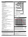
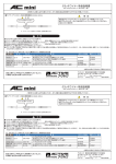
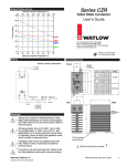
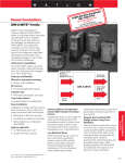
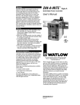
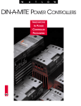
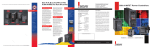
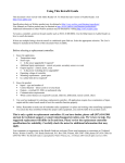
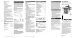
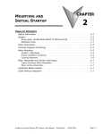
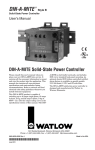
1241 Bundy Boulevard, P.O. Box 5580, Winona, Minnesota USA 55987-5580
Phone: +1 (507) 454-5300, Fax: +1 (507) 452-4507, Internet: http://www.watlow.com
Congratulations on your purchase of a Watlow
DIN-a-mite solid state power control. This
product represents the state-of-the-art in solid
state power control design. Please consult this
user’s manual when placing your new DIN-amite in service. It contains all the necessary
information to mount and wire it into the
application. This manual also contains all
pertinent specifications and semiconductor
fusing recommendations. Please refer to
national and local electrical code safety guidelines whenever installing electrical equipment.
This DIN-a-mite product is capable of switching
up to 100 amps single phase, at 600VÅ at 30°C,
depending on the model selected. It is electrically touch-safe and includes: standard back-panel
mounting; on-board semiconductor fuses; and a
current transformer option for external load current monitoring. A shorted SCR alarm option can
notify the user of a shorted SCR condition. This
is done via a circuit that monitors load current
and input command signal simultaneously. If
there is load current when there isn’t a command signal, a secondary triac output will energize in about 3-4 seconds elapse time. This triac
output can be wired to a remote alarm indicator.
The DIN-a-mite D mounting footprint matches
that of an industry standard 100 amp mercury
displacement relay. This DIN-a-mite is CE
Approved, UL 508 listed, C-UL and VDE 0160.
User's Manual
R
DIN-a-mite® Style D
Solid State Power Control
0600-0025-0013 Rev C
Supersedes
0600-0025-0013 Rev B
June, 2000, North American English
Made in the U.S.A.
Printed on Recycled Paper
10% Postconsumer Waste
Unit Dimensions
8.0" (203mm) Clearance For Air
Flow and Bending Radius
Side
.5" (13mm) Clearance
For Air Flow
.50"
(13mm)
7.28"
(185mm)
2.13"
(54mm)
8.00"
(203mm)
7.00"
(178mm)
Mounting
Footprint
2.63"
(67mm)
2.63"
(67mm)
2.38"
(61mm)
8.00"
(203mm)
8.0" (203mm) Clearance For Air
Flow and Bending Radius
Top
GroundingScrew
3/8" - 16" UNC
2.58"
(66mm)
2.50"
(64mm)
ç
.50"
(13mm)
Allowance For #10 Fastener
Metric = M5
∫3
Fuse Replacement
9.41"
(239mm)
5
ç
ç
∫1
∫2
∫3
∫4
5
WARNING: Wiring must conform to National Electric Code
(NEC) safety standards, as well as locally applicable codes.
Failure to do so could result in personal injury or death.
∫3
Å or 480VÅ
Å
WARNING: Wiring examples show L2 in 240VÅ
Å applications,
configuration. In 120VÅ
L2 is neutral and must not be fused or switched. Failure to
follow this guideline could result in personal injury or
death.
WARNING: Installation and service should be performed by
qualified personnel only. Failure to follow this guideline
could result in damage to equipment, and personal injury
or death.
WARNING: All signal and alarm wires must be tied together
beneath the cover. Failure to follow this guideline could
result in personal injury or death.
WARNING: Hot surface, do not touch heat sink. Failure to
follow this guideline could result in personal injury.
After removing all power, use a 7/16-in.
nut driver to remove fuse mounting
nuts. Torque to 40 in. lbs.
2
WATLOW DIN-a-mite Style “D” User’s Manual
1Ø Output and Input Wiring
L1
4-20mA Input:
Pin 1 (+)
Pin 2 ( -)
ç
∫3
Semiconductor
Fuses
VÅ Input:
Pin 1
Pin 2
∫4
Limit Control
Contacts
(If Required)
1
4.5-32VÎ (dc) Input:
Pin 1 (+)
Pin 2 ( -)
NOTE: Line (1) and Load (2) terminals
are 3/16" Allen head screws.
1
2
3
4
Alarm or CT Output
Alarm or CT Output
(Model Number Dependent)
Torque Procedure:
1. While connecting the line and load wires,
ensure that all wire strands are inside the
connector. Do not allow loose wire strands
to hang out of the connector. Once the
wire is installed, torque these same
connections to 80-90 in.-lb. (9.0-10.1 Newtonmeters). Use a dial or digital type torque
wrench and hold the torque at 80-90 in.-lb.
for 30 seconds. The 30 second hold allows
the wire to settle, minimizing the wire cold flow.
Current Sensing Option
DD1X-1MXX-XX10
3
4
Current Monitor
or Indication
2
On-Board
CT
Heater
Non-latching Alarm Option
DD1X-1MXX-XXS0
VÅ
1A
Alarm
Indicator
3
4
L1 for all
Voltages
2. Re-torque the same connections after 48 hours.
On-Board
Triac
3. Develop a maintenance program to re-torque
all load and line connections every three to
six months.
240VÅ
and above
The Watlow DIN-a-mite alarm option provides shorted output
protection. If there is output current and no input command signal,
the DIN-a-mite triggers an alarm. Typical indicators such as a
latching limit, light, or audible alarm (customer-supplied) are
triggered by the DIN-a-mite triac, rated for 0.3A ac at 25°C and
0.125A ac at 80°C.
L2, or Neutral on 120VÅ and
277VÅ applications.
The neutral must not be switched.
System Wiring Example
L1
120VÅ
Disconnect
L2
Contacts
Earth Ground
∫3
Series 935
935A-1CD0-000G
OT1 OT2 POWER
IN
100-240
S2 S1
VOLTS
- + - + - +
1 2 3 4 5 6 7 8
Coil
High Limit
Contactor
Branch Circuit
Fuse
Fuse
ç
High
Limit Light
1
DIN-a-mite
DD1C-1M24-C000
1
+
-
2
3
4
5
Series 92 Limit
2
92A3-1DJ1-DC
Heater
10 11
13 14
L2
(+)
Process Sensor
Limit Sensor
(-)
Optional Normally Open
Momentary
Switch
WATLOW DIN-a-mite Style “D” User’s Manual
3
(1804)
Control Mode-Zero Cross
• VÅ input contactor
• VÎ (dc) input contactor
• 4-20mA variable time base control
Operator Interface
• Command signal input
• Input signal indication LED
• Load current sensing output
• Shorted SCR detector output and indication LED
Input Command Signal
• 22, 120, 240VÅ @ 13mA max
• 4.5 - 32 VÎ (dc): max. current @ 4.5VÎ (dc) is 8.5mA per leg plus 1.2mA
LED current
• 4-20mA Î (dc): 375 ohms input impedance, loop powered. Output
control Type ‘V’ option only.
Output Voltage
• 22 to 50VÅ
• 120-240VÅ units: 48VÅ min. to 280VÅ max.
• 277-600VÅ units: 80VÅ min. to 660VÅ max.
• Off State Leakage: 1mA at 25°C max.
Amperage
• 1 phase, 100A output maximum at 30°C into a resistive load.
See output rating curve.
• Max. surge current for 16.6mSec. 1,750 amp peak
• Max. I2t for fusing: 12,750 A2Sec.
• Holding current: 200mA min.
• Latching current: 400mA min.
Operating Environment
• Up to 80°C. See output rating curve for your application.
• Contactor VÎ (dc) / VÅ type input cycle time should be less than 3 seconds for longest DIN-a-mite service life.
• Insulation tested to 3,000 meters
• Units suitable for “Pollution degree 2”
• 0 to 90% RH, non-condensing
• 50/60 Hz independent
Agency Approvals
• UL508 listed and C-UL File #E73741
• CE with proper filter:
89/336/EEC Electromagnetic Compatibility Directive
EN 50081-2: 1994 Emissions; EN 50082-2: 1995 Immunity
73/23/EEC Low Voltage Directive
VDE 0160, License #91623
Terminals
2
• 3/16” Allen head compression - will accept #2-6 AWG (16-35mm )wire
• Torque to 80-90 in.-lb. (9.0-10.2 Newton-meters)
Mounting
• Standard back panel mounting;
fits the same mounting pattern as a 100A 1Ø MDR
• Mounting holes offer clearance for #10 screw
• On-board semiconductor fusing, Bussmann P/N 170N3437
Current Sensing
• On-board current transformer, 0.1VÅ output signal per
amp into 100 ohms
Shorted Output Alarm Option
• Triac output 24/240VÅ 300mA @ 25°C, 125mA @ 80°C
• Energizes on alarm
• Holding current 200µA max.
• Latching current 5mA typical.
Dimensions
• See page 2
• Weight: 6.5 lbs. (2.9 kg)
Specifications are subject to change without notice.
Note: User documentation may be available in French, German, Spanish, Italian,
and Dutch, as well as English. Check Watlow’s website (www.watlow.com/) for
availability. Specify language at time of order.
Returns
1.
2.
3.
4.
4
Call Customer Service, +1 (507) 454-5300, or send a fax to +1 (507) 452-4507 for a
Return Material Authorization (RMA) number before returning any item for repair.
Make sure the RMA number is on the outside of the carton, and on all paperwork
returned. Ship on a freight prepaid basis.
A restocking charge of 20% of the net price is applied for all returned stock controls
and accessories.
If the unit is unrepairable, it will be returned to you with a letter of explanation. Repair
costs will not exceed 50% of the original cost.
WATLOW DIN-a-mite Style “D” User’s Manual
Ordering Information
(1811)
D D 1 __ - 1 M __ __ - __ __ __ 0
Part Number
Style “D”
Phase
1
= Single phase
Control Type
C
= Zero-cross contactor
V
= Zero-cross variable time
base (4-20mA Î [dc] only)
Amperage
1M = 100Amp
Output Voltage
02 = 22 to 50VÅ
24 = 120 to 240VÅ
60 = 277 to 600VÅ
Input Type
C0 = Zero-cross VÎ (dc) contactor
F0 = Zero-cross 4-20mA input (variable time base only)
K1 = Zero-cross 24VÅ contactor
K2 = Zero-cross 120VÅ contactor
K3 = Zero-cross 240VÅ contactor
Current Sensing or Alarm Option
0
= Neither Option
1
= Current Sensing (includes one current transformer)
S
= Shorted SCR Detector (includes one current transformer)
Replacement Fuse
Watlow P/N:
0808-0096-0000
(Bussmann P/N:
170N3437)
Output Rating Curve
Maximum Ambient Inside Cabinet (°C )
Specifications
DIN-a-mite Style D Natural Convection at 100% On
85
80
75
70
65
60
55
50
45
40
35
30
25
0
5 10 15 20 25 30 35 40 45 50 55 60 65 70 75 80 85 90 95 100 105
Current (Amps) Into a Resistive Load
Warranty
The DIN-a-mite is warranted to be free of defects in material and
workmanship for 36 months after delivery to the first purchaser for
TOTAL
use, providing that the units have not been misapplied. Since
CUSTOMER
Watlow has no control over their use, and sometimes misuse, we
SATISFACTION
cannot guarantee against failure. Watlow's obligations hereunder, at
Watlow's option, are limited to replacement, repair, or refund of
purchase price, and parts which upon examination prove to be defective within the warranty period specified. This warranty does not apply to damage
resulting from transportation, alteration, misuse, abuse or improper fusing.
Technical Support
If you encounter a problem with your Watlow controller, verify that your wiring is
correct for your specific model number. If the problem persists, an Application
Engineer can discuss your application with you.
Before calling, please have the complete model number and user’s manual available. You can get technical support by dialing +1 (507) 494-5656, 7:00 a.m. to 7:00
p.m. Central Standard Time.
The DIN-a-mite D User’s Manual is copyrighted by Watlow Winona, Inc., © June
2000, with all rights reserved. (1803)