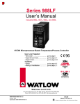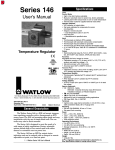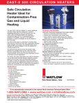
1
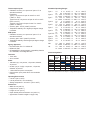
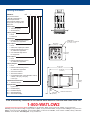
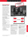
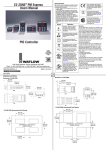
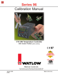
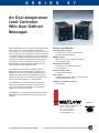
S E R I E S
9 7
An Over-temperature
Limit Controller
With User Defined
Messages
Watlow’s SERIES 97 is a microprocessor-based controller
with a single input, second auxiliary input and four
outputs. Input one is used to measure temperature from a
sensor. Input two can be utilized as a remote reset switch
or a hardware lockout switch. With up to four outputs, the
controller is versatile in handling applications that require
a high/low limit, alarms, retransmit and communications.
The control is so user friendly that it can be set up to
display safety and limit messages created by the end
user to meet the exact application need.
The SERIES 97 limit controller is added to thermal
applications to limit over-temperature conditions. The
SERIES 97 limit controller provides safety assurance
against instances where a high temperature runaway
condition could occur from a shorted input sensor or an
output device that could fail in a closed position.
The SERIES 97 is recommended for any application
where thermal runaway could result in large product
scrap costs, affect operator safety, cause damage to
equipment or create a fire hazard.
Features and Benefits
Programmable messages
• Controller can be set up to display user
programmed limit message
NEMA 4X (IP65)
• Water and corrosion resistant; front panel
can be washed down
Microprocessor-based
• Accurate set point settings and quick
output response
Second auxiliary input
• Remote reset capability
Four outputs
• Handles high/low limit, alarms, communication
and retransmit requirements
Software and hardware lockouts
• High security
The SERIES 97 is manufactured by ISO 9001 registered
Watlow Winona and reliably backed up by a three-year
warranty.
WIN-97-1203
1241 Bundy Boulevard
Winona, Minnesota 55987-5580 USA
Phone: +1 (507) 454-5300
Fax: +1 (507) 452-4507
Internet: www.watlow.com
e-mail: [email protected]
© 2003 Watlow Electric Manufacturing Company
ISO 9001
Registered Company
Winona, Minnesota USA
Printed in the USA on Recycled Paper, 15 Percent Postconsumer Waste
Specifications
Controller
• Microprocessor-based
• Universal input 1, auxiliary input 2, 4 outputs
• Input sample period; Single input 10Hz (100 msec),
dual input 5Hz (200 msec) digital filter adjustable
• Display update; 2Hz (500 msec), time filter adjustable
• Input/Output/Communication isolation
• Displayed in °C, °F
Operator Interface
• Dual 4-digit LED displays: upper 10.2 mm (0.4 in.),
lower 6.2 mm (0.244 in.)
• Advance, Up Arrow, Down Arrow, Reset tactile keys
Standard Conditions For Specifications
• Ambient temperature 77°F (25°C) ±3°C, rated line
voltage, 50 to 60Hz, 0 to 90 percent RH
non-condensing,
15 minute warm-up
Universal Input 1
Thermocouple
• Type J, K, T, N, C (W5), E, PTII, D (W3), B, R, S
thermocouple types
• >20MΩ input impedance
• Maximum 20Ω source resistance
• 30mA open detection bias
RTD
• 2- or 3-wire platinum, 100Ω
• JIS and DIN curves
• Whole or tenth degree indication
• 150µA nominal RTD excitation current
Input 2
Event Input
• Contact or voltage
• 20KΩ input impedance
• Voltage input: event high state 3 to 36VÎ(dc),
event low state 0 to 2VÎ(dc)
• Resistance/contact input: event high state > 23kΩ,
event low state 0 to 2kΩ
Output Types
Open Collector/Switched DC
• Open collector configuration:
Maximum voltage 42VÎ(dc)
Maximum current 200mA
Maximum “on” resistance 1.1Ω
Maximum offstate leakage current 100µA
• Switched dc configuration:
Switched dc supply voltage 22 to 28VÎ(dc)
dc supply current limited to 30mA
Solid State Relay
• Optically isolated
• Zero cross switched
• Without contact suppression
• Minimum load current 0.5mA rms
Solid State Relay (cont.)
• Maximum current 0.5A rms at 20 to 280VÅ(ac)
• Maximum offstate leakage current 10µA rms
• For resistive loads only, must use RC suppression for
inductive loads
Electromechanical Relay
• Form C contact configuration
• Minimum load current 10mA @ 5VÎ(dc)
• Rated resistive and inductive loads: 2A @ 250VÅ(ac)
or 30VÎ(dc) maximum
• Electrical life 100,000 cycles at rated current
• For resistive loads only, must use RC suppression for
inductive loads
Retransmit
• Range selectable: 0-20mA, 4-20mA, 0-5VÎ(dc),
1-5VÎ(dc), 0-10VÎ(dc)
• 0 to 10VÎ(dc) voltage output into a 1,000Ω minimum
load resistance
• 0 to 20mA current output into an 800Ω maximum load
resistance
• Resolution:
Vdc ranges = 2.5mV nominal
mA ranges = 5µA nominal
• Calibration accuracy:
Vdc ranges = ±15mV
mA ranges = ±30µA
• Temperature stability 100ppm/°C
Communications
• EIA/TIA-485, EIA/TIA-232
• Opto-isolated
• ModbusTM RTU protocol
• 1200, 2400, 4800, 9600, 19200 baud rates
• 32 maximum units can be connected (With additional
485 repeater hardware, up to 247 units may be
connected)
Accuracy
• Input ranges
Type J:
Type K:
Type T:
Type N:
Type E:
Type C(W5):
Type D(W3):
Type PTII:
Type R:
Type S:
Type B:
DIN:
JIS:
0
-200
-200
0
-200
0
0
0
0
0
870
-200
-200
to
to
to
to
to
to
to
to
to
to
to
to
to
750°C
1250°C
350°C
1250°C
900°C
2315°C
2315°C
1393°C
1450°C
1450°C
1700°C
800°C
630°C
or
or
or
or
or
or
or
or
or
or
or
or
or
32
-328
-328
32
-328
32
32
32
32
32
1598
-328
-328
ModbusTM is a trademark of AEG Schneider Automation.
to
to
to
to
to
to
to
to
to
to
to
to
to
1382°F
2282°F
662°F
2282°F
1470°F
4200°F
4200°F
2540°F
2642°F
2642°F
3092°F
1472°F
1166°F
Thermocouple Inputs
• Calibration accuracy ±0.1 percent of span ±1˚C at
standard conditions
Exceptions:
Type T; 0.12 percent of span for -200°C to -50°C
(-328°F to -58°F)
Types R and S; 0.15 percent of span for 0°C to 100°C
(32°F to 212°F)
Types B; 0.24 percent of span for 870°C to 1700°C
(1598°F to 3092°F)
• Accuracy span: 540°C (1000°F) minimum
• Temperature stability: ±0.1 degree per degree change
in ambient
RTD Inputs
• Calibration accuracy ±0.1 percent of span ±1˚C at
standard conditions
• Accuracy span: 540°C (1000°F) minimum
• Temperature stability: ±0.05 degree per degree change
in ambient
Agency Approvals
• FM Class 3545, File # J.I. 1B5A6.AF
• NEMA 4X, IP65
• CE 89/336/EEC, electromagnetic compatibility directive
CE 73/23/EEC, low-voltage directive
Allowable Operating Ranges
Type J:
1.0
0
0.1
0.0
Type K:
1.0 -270
0.1 -199.9
Type T:
1.0 -270
0.1 -199.9
Type N:
1.0
0
0.1
0.0
Type E:
1.0 -270
0.1 -110.0
Type C:
1.0
0
0.1
0.0
Type D:
1.0
0
0.1
0.0
Type PTII: 1.0
0
0.1
0.0
Type R:
1.0
0
Type S:
1.0
0
Type B:
1.0
0
to
to
to
to
to
to
to
to
to
to
to
to
to
to
to
to
to
to
to
DIN
to 800°C or -328
to 800.0°C or -199.9
to 630°C or -328
to 630.0°C or -199.9
JIS
Operating Environment
• 0 to 65°C (32 to 149°F)
• 0 to 90 percent RH, non-condensing
• Storage temperature: -40 to 85°C (-40 to 185°F)
Dimensions
• Width 52 mm (2.05 in.)
• Height 52 mm (2.05 in.)
• Length 107 mm (4.2 in.)
• Depth behind panel surface 98.4 mm (3.875 in.)
• Approximate controller weight 0.2 kg (0.4 lbs)
or
32 to 1500°F
or 32.0 to 999.9°F
or -454 to 2500°F
or -199.9 to 999.9°F
or -454 to
750°F
or -199.9 to 750.0°F
or
32 to 2372°F
or 32.0 to 999.9°F
or -454 to 1470°F
or -199.9 to 999.9°F
or
32 to 4200°F
or 32.0 to 999.9°F
or
32 to 4200°F
or 32.0 to 999.9°F
or
32 to 2543°F
or 32.0 to 999.9°F
or
32 to 3200°F
or
32 to 3200°F
or
32 to 3300°F
to 1472°F
to 999.9°F
to 1166°F
to 999.9°F
Functionality Matrix
Terminals
• Touch safe
• 22 to 12 AWG
Power
• 100-240VÅ(ac) +10 percent, -15 percent; 50/60Hz,
±5 percent
• 24-28VÅ(ac) or VÎ(dc) +10 percent, -15 percent;
50/60Hz, ±5 percent
• 7.0VA maximum power consumption
• Data retention upon power failure via nonvolatile
memory
1.0 -200
0.1 -199.9
1.0 -200
0.1 -199.9
815°C
815.0°C
1370°C
999.9°C
400°C
400.0°C
1300°C
999.9°C
800°C
800.0°C
2315°C
999.9°C
2315°C
999.9°C
1395°C
999.9°C
1760°C
1760°C
1816°C
Universal
Input
Event
High/
Low
Limit
High/
232
Low
485
Alarm Retransmit Comm
Input 1
Input 2
Output 1
Output 2
Output 3
Output 4
Note: These specifications are subject to change without prior notice.
Ordering Information
SERIES 97
97
-
-
Microprocessor-based
1
⁄16 DIN with universal input 1,
thermocouple and RTD.
Options include: software, power
supply, input 2, four outputs and
display color
Power Supply
A
= 100-240Vı(ac/dc)
B
= 24-28Vı(ac/dc)
Auxiliary Input 2
0
= None
1
= Event input
Limit Output 1
D
= Electromechanical relay, Form C,
2A, without RC suppression
Panel Cutout
44.958 mm x 44.958 mm
(1.77 in. X 1.77 in.)
Alarm Output 2
52.070 mm
(2.050 in.)
A
= None
C
= Switched dc output/open collector
D
= Electromechanical relay, Form C,
2A, without RC suppression
K
= 0.5A solid state relay without
RC suppression
96
1
2
3
4
%
52.070 mm
(2.050 in.)
Alarm Output 3
RESET
A
= None
D
= Electromechanical relay, Form C,
2A, without RC suppression
Auxiliary Output 4
A
= None
D
= Electromechanical relay, Form C,
2A, without RC suppression
R
= 232 Communications
U
= 485 Communications
M
= Universal Retransmit, range selectable: 0-20mA,
4-20mA, 0-5VÎ(dc), 1-5VÎ(dc),
0-10VÎ(dc)
107.747 mm
(4.242 in.)
98.425 mm
(3.875 in.)
59.182 mm
(2.330 in.)
Software/Preset Parameters
00 = Standard software
Display/Overlay
Upper/Lower
RR = Red/Red display
RG = Red/Green display
GR = Green/Red display
GG = Green/Green display
9.322 mm
(0.367 in.)
Customer's Front Panel
To be automatically connected to the nearest North American Technical and Sales Office call:
1-800-WATLOW2
International Technical and Sales Offices: Australia, +61 (39) 335-6449 • China, +86 (21) 6277-2138 • France, +33 (01) 3073-2425 •
Germany, +49 (0) 7253-9400-0 • Italy, +39 (02) 458-8841 • Japan, +81 (03) 5403-4688 • Korea, +82 (02) 575-9804 • Malaysia, +60 (4) 641-5977 •
Mexico, +52 (442) 217-6235 • Singapore, +65 6773-9488 • Spain, +34 916 759 192 • Sweden, +46 31 7014959 • Taiwan, +886 (0) 7-288-5168 •
Sweden, +46 31 7014959 • United Kingdom, +44 (0) 115-964-0777