1
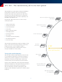
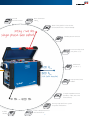
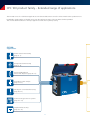
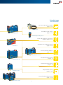
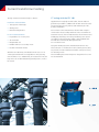
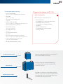
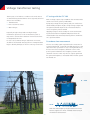
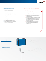
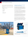
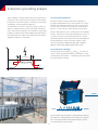
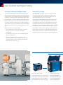
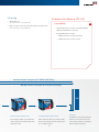
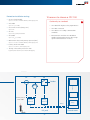
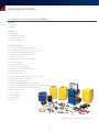
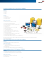
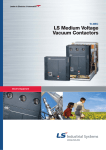
CPC 100
Multi-functional primary test system for
substation commissioning and maintenance
CPC 100 – The revolutionary all-in-one test system
The patented test system replaces numerous individual
testing devices and offers new, innovative testing
methods. This makes testing with the CPC 100 a timesaving and cost-effective alternative for conventional
testing methods. Despite its expansive capabilities, the
CPC 100 is very simple to use.
Turns ratio meter for transformers,
CTs and VTs
Using the CPC 100, electrical tests on various assets
can be performed:
> Current transformers
High-current injection
transformer
> Voltage transformers
> Power transformers
> Power lines
> High-voltage (HV) cables
> Grounding systems
> Rotating machines
Power meter (P, Q, S)
> GIS systems
> Switchgear and circuit breakers
> IEC 61850 installations
> Protection relays
The powerful testing device provides up to 800 A or 2 kV
(2 kA or 12 kV with accessories) with up to 5 kVA over a
frequency range of 15 Hz to 400 Hz or 400 ADC.
Excitation
curve tester
2 kV
Its compact design (29 kg / 64 lbs) makes it easy to
transport and ideal for on-site testing.
12 kV (with booster)
Testing with variable frequency
Phase angle
meter
The CPC 100’s variable output frequency allows the use
of test frequencies different from the mains frequency
offering a very effective suppression of mains-related
interference. Thus the CPC 100 is able to obtain very
accurate results even in extremely noisy environments.
Another critical advantage to performing measurements
at different frequencies is the opportunity this provides to
gain more information about the asset under test.
Line impedance and
cable measurement
The CPC 100 utilizes switched mode amplifiers and
frequency shift techniques to generate its variable output
frequency.
On load tap changer
test equipment
2
Ground
resistance meter
Micro ohmmeter
400 ADC
Tester for Rogowski coils and other
unconventional CTs / VTs (IEC 61850)
29 kg / 64 lbs
single phase wall outlet
Winding resistance meter
Protection relay tester
(one phase V, I, f)
Multimeter
(V, I, R, Z, ...)
400 ADC
800 AAC
2 kA (with booster)
Step up transformer
2 000 V
Complex impedance meter
(burdens, cables, lines and
transformers)
15 Hz - 400 Hz
Vector group verification system
for power transformers
Polarity
checker
Power / dissipation factor
measurement set
3
CPC 100 product family – Extended range of applications
The CPC 100 covers a lot of different applications in and around substations as well as at the manufacturer’s production site.
Extended by a high number of valuable accessories the application range of the CPC 100 is further expanded.
Thus it is the ideal instrument for all major applications in the area of primary testing.
CPC 100
Applications
Current transformer testing
(page 6 – 7)
Voltage transformer testing
(page 8 – 9)
Power and distribution
transformer diagnosis (page 10 – 11)
Grounding system analysis
(page 14 – 15)
Switchgear / circuit breaker testing
(page 20 – 21)
Primary test system
Commissioning protection systems
(page 22 – 23)
Sampled Values testing
(page 24 – 25)
4
Extended range
with accessories
HV cable and power line analysis
(page 12 – 13)
Grounding box
Grounding system analysis
(page 14 – 15)
Coupling unit
Handheld grounding tester
Power and distribution transformer
diagnosis (page 10 – 11)
Switchgear / circuit breaker testing
(page 20 – 21)
Switch box
Rotating machine diagnosis
(page 16 – 17)
Compensation reactor
Voltage transformer testing
(page 6 – 7)
Tan Delta test set
Current transformer testing
(page 8 – 9)
Sampled Values testing
(page 24 – 25)
Current booster
Gas Insulated Switchgear testing
(page 18 – 19)
Resonance circuit
5
M/G
Current transformer testing
CT testing with the CPC 100
Testing current transformers helps to detect:
Supplied from a single phase wall outlet, the CPC 100 can
generate up to 800 A AC (2 000 A with CP CB2 current booster)
for injecting into the CT‘s primary side and testing its ratio,
polarity and burden.
Installation related failures:
> Transportation damages
> Wiring errors
> Manufacturing defects
For excitation curve measurement, the CPC 100‘s output is
connected to the secondary terminals of the core. Within an
automatic test run, the CPC 100 measures the excitation curve
and displays the knee point voltage and knee point current
(according to the relevant IEC or IEEE / ANSI standard). The
CPC 100 also automatically demagnetizes the
CT core after the test.
In-service related failures:
> Degradation of accuracy class
> Shorted turns
> Magnetized core
> Burden failures in secondary circuit
Using the winding resistance measurement function also
allows the user to calculate the accuracy limiting factor (ALF)
for protection circuits and the instrument security factor (FS)
for metering circuits.
> Insulation material failures
With the CPC 100 many standard electrical tests for CTs
can be performed with one single device saving testing
time and labor costs. Additionally, unconventional CTs, like
Rogowski coils and IEC 61850 integrated systems, can also
be tested.
The CT winding resistance and power / dissipation factor can
also be measured.
0 ... 800 A
0 ... 2 kV
6
10 reasons to choose a CPC 100
Current transformer testing
> CT ratio (with burden)
up to 800 A or 2 000 A with CP CB2, 5 kVA output power
Multi-functionality
> CT burden
up to 6 A AC | secondary
1
With one easy-to-use system you can:
> CT excitation curve (knee point)
> Test several assets
up to 2 kVAC
(for example CT, VT, CB, power transformer)
> Polarity check with CPOL
> Test different parts of an asset
up to 800 A or up to 2 000 A with CP CB2, 5 kVA output power
(for example core, windings, bushing,
insulation)
> Accuracy limiting factor (ALF) test
> CT ratio with voltage
> Perform numerous tests
up to 130 VAC | bushing CTs
(for example ratio, polarity, burden,
excitation current)
> CT winding resistance
up to 6 ADC
> CT voltage withstand test
up to 2 kVAC
> CT ratio Rogowski and CT ratio low power
up to 800 A or up to 2 000 A with CP CB2, 5 kVA output power
> Power / dissipation factor (tan δ) test
up to 12 kV, 300 mA | with CP TD1
> IEC 61850 Sampled Values testing
With the CP CB2 primary injection of current up to
2 kA can be realized for CT testing.
CP CB2 (current booster)
2 kA
For high-voltage CTs, insulation material tests
are very important and can be easily done with
the CP TD1 accessory.
CP TD1 (tan δ)
12 kV
The CPOL can check the correct polarity along the
different connection points in the secondary wiring
by analyzing the sawtooth signal injected into the
CT’s primary side using the CPC 100.
CPOL (polarity checker)
7
Voltage transformer testing
VT testing with the CPC 100
The majority of VT failures occur due to electrical stresses
or manufacturing and installation errors. Typically electrical
stresses are caused by:
With a voltage output of up to 2 000 VAC the CPC 100 can be
used to test VT ratio, polarity and burden.
> Thunderstorms
By injecting voltage into the primary side, ratio can be measured. Thereby the phase angles of high-voltage output and
voltage measurement input are also measured. Thus the
correct VT polarity can be verified.
> Ferro-resonances effects
> Over-voltages
Applying voltage to the secondary VT circuits and measuring the load current in amplitude and phase allows the
actual burden to be measured, ensuring that it is within the
VT´s specification data.
Especially in high-voltage and extra high-voltage
installations supervision of the VT insulation system is
important to ensure that its dielectric characteristics have
not degraded over time.
In case of (re-)commissioning of substations VT circuits
should also be checked. Verifying the VT´s nameplate data
helps to identify damages of the VT or wrong connections.
Disturbance-free measurement
The VT‘s secondary signal may be difficult to measure if it
is small in amplitude – especially if neighboring parts of the
substation are in operation. In case of strong disturbances,
the user can select a frequency different to that of the
power system and utilizes the “frequency selective measurement” function. Thus only the VT‘s output signal with
this particular frequency is measured while all other signals
are filtered out.
0 ... 2 kV
15 Hz
400 Hz
With the wide frequency range excellent noise interference suppression can be achieved when testing in
the harsh HV environment.
8
10 reasons to choose a CPC 100
Voltage transformer testing
> VT ratio
up to 2 kVAC | polarity and burden
Variable frequency
> VT burden
up to 130 VAC | secondary
2
> Voltage and current injection with
> VT secondary voltage withstand test
variable frequency
up to 2 kVAC
> Suppression of mains-related interference
> Polarity check with CPOL
and disturbances
up to 2 kVAC
> Test results at different frequencies provide
> VT electronics
more detailed information about an asset
(for example more information about the
insulation condition)
up to 2 kVAC
> IEC 61850 Sampled Values testing
> Power / dissipation factor (tan δ) test
> Variable frequency testing is necessary
up to 12 kV, 300 mA | with CP TD1
for some standardized and advanced
diagnostic tests
For high-voltage VTs, insulation material tests
are very important and can be easily done with
the CP TD1 accessory.
CP TD1 (tan δ)
12 kV
CPOL (polarity checker)
The CPOL can check the correct polarity along
the different connection points in the secondary
wiring by analyzing the sawtooth signal injected
into the VT’s primary side using the CPC 100.
9
Power transformer testing
Testing power transformers – Most common
electrical tests with one device
Testing to assess the health of power transformers and
to diagnose problems is of utmost importance to ensure
the long-term and safe operation of these very expensive
power assets.
The CPC 100 provides an easy and accurate (4-wire connection) winding resistance measurement. Automatic
measurement for tapped windings (by using CP SB1 with
the on load tap changer) speeds up the measurement. The
CPC 100 automatically discharges the inductive energy,
which makes the measurement safe.
With the CPC 100 power transformers and their ancillary
components can be tested:
> Windings
> Tap changer
After switching off a transformer or after applying DC signals to a transformer, the core remains magnetized. This
can cause problems for further diagnostic measurements
or can lead to higher inrush currents. By using the CP SB1
switch box the integrated algorithm in the CPC 100 completely demagnetizes the transformer core.
> Bushings
> Insulation
> Core
> Connection leads
> Surge arrestors
For measuring ratio and excitation current, the CPC 100
provides a 2 kV output, delivering 2500 VA. The test voltage is generated digitally and the current is automatically
measured within the CPC 100. This makes the measurement highly accurate, easy to set up, fast and safe.
For power / dissipation factor (PF / DF) measurement of
power transformers and bushings, the CPC 100 is combined with the CP TD1. Measuring this factor over a broad
frequency range – in addition to mains frequency – helps
to better assess the insulation condition, for example
detect whether the cellulose or the oil is contaminated by
moisture.
0 ... 2 kV
1Ø
15 Hz
400 Hz
The wide frequency range of 15 Hz to 400 Hz is needed for
advanced tan δ tests, which give the user important information
about the transformer aging.
10
10 reasons to choose a CPC 100
Power transformer testing
> DC winding resistance
up to 100 ADC
Testing and reporting
> Transformer demagnetization
with CP SB1
3
> Offline test preparation possibilities
> Dynamic load tap changer diagnostics
(time-saving and less error-prone)
(on load tap changer test)
> CPC 100 software automatically guiding
up to 100 ADC | optionally with CP SB1
the user through the test
> Transformer turns ratio (TTR) per tap
> Automated report generation
up to 2 kVAC | including polarity and excitation current |
> Customizable test reports (for example
IEC 61387-1 support for transformer with unconventional vector groups
different languages, customer logo)
> Automatically determination of the transformer’s
vector group
with CP SB1
> Leakage reactance / short circuit impedance
up to 6 A AC
> Transformer, bushing: power / dissipation factor (tan δ)
+ insulation capacitance
up to 12 kV, 300 mA | frequency from 15 Hz to 400 Hz | with CP TD1
> Insulating fluids: power / dissipation factor (tan δ)
up to 12 kV, 300 mA | with CP TD1 and CP TC12
> Excitation current per tap
up to 12 kV, 300 mA | with CP TD1
> Frequency response of stray losses (FRSL)
> Surge arrestors: leakage current and watt losses
up to 12 kV, 300 mA | with CP TD1
Insulation condition assessment of
transformers, bushings and insulation fluids
(with the CP TC12).
CP TD1 (tan δ)
12 kV
CP SB1 (switch box)
The CP SB1 switch box is the connection
between transformer and CPC 100.
Connecting all phases simultaneously avoids
wiring errors and the need to repeatedly
climb the transformer. Automatic OLTC control
speeds up testing.
3 Ø, N
11
HV cable and power line testing
Line parameter measurement
For a reliable power supply, selective operation of protection relays is crucial. Over- and underreach can be
avoided by having correct relay settings, and line data.
Therefore it is necessary to determine line parameters,
such as positive sequence impedance, zero sequence
impedance or k-factors.
With the CPC 100 and the CP CU1 the impedance of
cables and power lines can be measured accurately, quickly
(in approximately two hours) and safely.
Line impedance and k-factor
Calculating impedances and the k-factor is highly errorprone. Measuring line and ground impedance eliminates
these errors and contributes to system reliability by providing proper relay settings.
X (in Ω)
The CPC 100 and the CP CU1 are used to inject current into
the different phase-phase and phase-ground loops of
a power line / cable, grounded at the other end, while
measuring voltage, current and phase angle. From the
measurement data of the different loops, line parameters
are calculated. Variable frequency injection allows measurements to be made despite coupling from live parts or
neighboring lines.
t (in s)
Mutual coupling
With this unique testing equipment, the mutual coupling
factor of parallel lines can also be determined, allowing the
correct parameterization of the mutual coupling algorithm
of modern line protection relays.
R (in Ω)
Z (in Ω)
CP CU1
15 Hz
400 Hz
Using variable output frequency, measurements with the CPC 100
are not influenced by mains frequency coupling. Precise and
reproducible measurement results, even in noisy environments,
are possible.
12
10 reasons to choose a CPC 100
Cable and transmission line diagnosis
> Line impedance and k-factor
up to 100 A | with CP CU1
Weight and size
> Mutual coupling
up to 100 A | with CP CU1
> Light-weight (29 kg / 64 lbs)
> Positive or zero sequence impedance
> Compact design
> Save costs on:
> Transport
> Handling
> Storage
(coupling unit)
CP GB1 (grounding box)
The CP CU1 allows the safe connection of the CPC 100
to a power line or HV cable. The impedance matching
transformer within the CP CU1 ensures optimum power
transfer from the CPC 100 to the power line.
The CP GB1 grounding box contains surge arrestors
to ensure safe testing during unexpected events.
13
4
Substation grounding analysis
Ground grid impedance
The grounding of a high-voltage electrical system helps to
ensure the safety of personnel. Voltage rises in the neighboring area of electrical systems, caused by a system fault
or lightning, can be extremely dangerous.
Using the current-voltage method, the challenge for
good ground impedance (Zgrid) measurements is to inject
sufficient measurement current into the soil at a remote
location and to measure the voltage rise caused by this
injection – and not by any other current in the ground.
Conventional test solutions, which use power system frequencies, need enormous power and complicated methods to overcome the problems of interference. Varying the
frequency and using narrowband digital filtering with the
CPC 100 and CP CU1 reduces the required power and the
equipment weight to a minimum.
The CPC 100 and CP CU1 test system meets this challenge.
It injects current at non-network frequencies into the soil
at a remote station via the existing power lines. It then
selectively measures the voltage rise at the used frequencies.
The measurements are performed according to international standards including DIN VDE 0101, CENELEC
HD637S1, IEEE Std 80-2000 and IEEE Std 81-1983.
V
Step and touch voltages
The step and touch voltages (Vstepand Vtouch ) of the local
station can be measured with the CPC 100 itself or more
conveniently with the HGT1 – a frequency selective voltmeter which minimizes wiring.
HV station
Vtouch
V = Zgrid * If
Vstep
Distance
CP CU1
15 Hz
400 Hz
Using variable output frequency, measurements with the
CPC 100 are not influenced by mains frequency coupling.
Precise and reproducible measurement results, even in
noisy environments, are possible.
14
10 reasons to choose a CPC 100
Ground system analysis
> Ground grid impedance for large systems
up to 100 A | with CP CU1
Safety
> Step and touch voltage
up to 100 A | with CP CU1 and HGT1
5
> Emergency switch-off button
> Ground grid impedance for small systems
> Ground connection check
up to 6 A AC
> Overload detection
> Soil resistivity
> Multiple isolated outputs
up to 6 A AC
> Safety key lock
> Integrity check of grounding connection
up to 400 ADC
> Discharge circuit to de-energize DC
> Reduction factor / current split factor
test objects
> Measure multiple current paths with Rogowski coil
> Strobe light
> 3-position safety switch
> Grounding box
CP GB1
(grounding box)
The CP GB1 contains surge
arrestors to ensure safe
testing during unexpected
events.
(coupling unit)
HGT1
(handheld
grounding tester)
The CP CU1 allows the safe connection of the CPC 100 to a power
line or HV cable. The impedance matching transformer within the
CP CU1 ensures optimum power transfer from the CPC 100 to the
power line.
15
The HGT1 is a handheld
measurement device to
measure step and touch
voltages within HV stations
and surrounding areas.
With the HGT1 extremely
long measurement cables
can be avoided.
Rotating machines diagnosis
“∆ tan δ” test and tip-up test
The most sensitive part in rotating machines is the insulation. The expected lifetime of a stator winding depends on
the ability of the insulation to prevent winding faults.
As maintenance tools for entire windings, the “∆ tan δ” test
and the tip-up test are used. Both tests are an indirect way
of determining if partial discharges (PD) are occurring in a
high-voltage stator winding.
High temperatures and high rates of temperature changes
can generate micro-voids particularly at the interface
between mica and resin, and between semiconductive layers and resin. Partial discharges in these voids will further
increase the void size by erosion and complete breakdowns
are inevitable.
An increase of the power factor / dissipation factor (tip-up)
from the normal level indicates that the winding has significant PD activity, as this is indicative of this condition.
The CPC 100, CP TD1 and CP CR500 test system allow
“∆ tan δ” and tip-up tests complying with the IEC 60894
and IEEE 286 specifications.
Therefore, experts strongly recommend the checking of
insulation for partial discharges during the whole lifecycle
of motors and generators. In order to check the insulation
a compensated high-voltage source is needed. The
CPC 100, CP TD1 and CP CR500 test system can be utilized
as a high-voltage source.
An acceptable power / dissipation factor offers assurance
that the coil or the bar were properly fabricated with inherently low-loss materials.
0 ... 2 kV
16
10 reasons to choose a CPC 100
Rotating machines diagnosis
> Power / dissipation factor (tan δ) tip-up test
at 50 Hz / 60 Hz
Product quality
up to 12 kV | max. 1 µF / 4 A| with CP TD1 and CP CR500
> Power / dissipation factor test with variable frequency
6
> Durable case design for rough environments
up to 12 kV | frequency from 15 Hz to 400 Hz | with CP TD1
with test field accuracy
> HV source for testing rotating machines
> Long lifetime due to high quality components
up to 12 kV | max. 2 µF | with CP TD1 and CP CR500
> Premium quality cables and clamps
> Comprehensive documentation (for example,
user manual with connection diagrams,
software help function, videos, application
notes)
CP CR500
CP TD1 (tan δ)
12 kV
(compensating reactor)
Insulation condition assessment of motors and
generators. The CPC 100 plus CP TD1 can provide
up to 12 kV and can also be used as a HV source.
17
The CP CR500 compensator reactor enables
the CP TD1 to be used with test objects
with large capacitance such as large motors
and generators.
Gas-insulated switchgear testing
Testing gas-insulated switchgear to date
Innovative GIS testing
Gas-insulated switchgears (GIS) are compact and are,
therefore, used in applications where space is limited. For
commissioning of GIS a high-voltage (HV) withstand test is
required in accordance with standards (IEC 62271-203).
With OMICRON’s CPC 100 + CP RC you can perform GIS
tests without the need of a big HV transformer. This
is possible because the system directly makes use of a
specially designed “Power VT” for testing.
To date the test voltage needed for a withstand test has
been produced by a resonance circuit. This test system
consists of an HV test transformer, a coupling capacitor
and a power control unit. The HV test transformer and the
coupling capacitor have to be connected directly to the
GIS.
This Power VT is an integral part of the GIS and generates
the required test voltage. CPC 100 injects power at the
low-voltage (LV) side of the VT, producing the necessary
voltage on the HV side. As you can directly connect the
measuring system to the integrated VT of the GIS system it
eliminates the need for draining and refilling any SF6 gas.
Weak points of this testing principle:
The CPC 100 + CP RC system comprises several small and
light-weight components (< 21 kg / 46 lbs) which can be
transported by one person. With its modular design you
can perform GIS tests even at test sites with limited space.
> The complete test system is difficult to transport,
because it consists of very heavy and large
components.
> It is difficult to use it at test sites with limited space,
such as wind turbines.
> The HV test lead must be connected to, and
disconnected from, the GIS system for testing. This
normally includes a time-consuming venting and
refilling process of the SF6 gas.
Auto-transformer CP AT1
Control unit CPC 100
The CP AT1 allows you to connect the
mains supply of the CPC 100 to a threephase 16 A power outlet, and delivers
the required power for the test setup.
The CPC 100 supplies
the required energy and
acts as both measuring
and controlling device.
18
10 reasons to choose a CPC 100
GIS testing
> Withstand test
up to 235 kV | max 1.6 nF | with CP RC2
Expandability
> High-voltage source for partial discharge measurements
up to 235 kV | max 1.6 nF | with CP RC2
7
> Further applications can be covered by adding
additional hardware accessories
> By upgrading the software:
> Additional tests can be performed
> Additional assets can be tested
CPC 100 + CP RC2: testing GIS up to 145 kV rated voltage
CPC 100 + CP RC1: testing GIS up to 123 kV rated voltage
GIS
Power VT
Isolation transformer CP TR
Compensating reactor CP CR
The CP TR provides a potential-free
output signal and compensates the
capacitive load.
With 4 mH (CP CR4) or 6 mH (CP CR6)
the CP CR compensates the capacitance
in a modular fashion.
19
In addition to the measurement
function of a VT the Power VT
offers the possibility to generate
high voltage for testing.
Switchgear and circuit breaker testing
Contact resistance measurement
Switchgear consists of busbars, circuit breakers (CB),
disconnectors and earthing switches. There are various
connections and contacts within the switchgear. Poorly
maintained or damaged contacts can cause arcing, single
phasing or even fire which can lead to the total loss of
the asset.
The CPC 100 can measure contact resistance by injecting a
current of up to 400 ADC into the contacts and measuring
the voltage drop (using the 4-wire method). The resistance
value can be compared to the value given by the manufacturer as well as to previous records.
Therefore, it is common practice to conduct contact resistance measurements to ensure that the connections have
been made with the appropriate contact pressure.
Insulation testing of circuit breakers
For power / dissipation factor (tan δ) measurements of
circuit breakers, the CPC 100 is combined with the CP TD1.
Measuring this factor over a wide frequency range – in
addition to mains frequency – helps to better assess the
insulation condition.
Additionally, the insulation of CBs within the switchgear
has to be tested. These assets are frequently exposed to HV
stresses, switching currents and very high fault currents,
which heat up the circuit breakers and impact on the insulation material.
Timing of CBs with overcurrent elements
For testing of CBs or load breaker switches with integrated
overcurrent elements, the CPC 100 can inject AC primary
currents up to 800 A (or 2000 A together with the current
booster CP CB2), and measure the time from the start of
the injection to the interruption of the current.
0 ... 2 kV
400 ADC
μΩ measurement with the CPC 100‘s 400 ADC capabilities
enables accurate contact resistance measurements on
circuit breakers.
20
10 reasons to choose a CPC 100
Switchgear / circuit breaker testing
> Contact resistance
up to 400 ADC
Support
> Bushing: power / dissipation factor (tan δ)
+ insulation capacitance
8
> International technical support
12 kV, 300 mA | frequency from 15 Hz to 400 Hz | with CP TD1
> On-site support for issues concerning testing,
> Overcurrent relays with primary injection (MV)
start-up and maintenance
up to 800 A or 2 000 A with CP CB2, 5 kVA output power
> Repair centers around the world
> Circuit breaker: Power / dissipation factor (tan δ)
> Local support by worldwide sales partner
up to 12 kV, 300 mA | frequency from 15 Hz to 400 Hz | with CP TD1
network
> Insulating fluids: power / dissipation factor (tan δ)
> Consulting on the development of individual
up to 12 kV, 300 mA | with CP TD1 and CP TC12
testing concepts
> Training classes around the globe
CP TD1 (tan δ)
Insulation condition assessment of
circuit breakers and insulation fluids
(with CP TC12).
12 kV
21
Commissioning and trouble shooting of protection systems
Commissioning protection systems
In order to work properly, protection and control systems
have to be correctly integrated into the substation or
power plant. Quantities from the primary system are transformed at the VTs and CTs – using their different cores
– and so the voltage and current signals must be correctly
connected to the protection relays, automation units and
meters.
The CPC 100 allows the verification of the ratio and polarity of CTs and VTs – preventing wrong connections, especially in the case of tapped CTs. Injecting current or voltage
into individual CTs / VTs and checking the reading at the
relay ensures that phases are not mixed up and that the
CT and VT ratio setting in the relay is correct.
From these protection and control units, the trip signals
are routed back to the primary apparatus, for example, the
circuit breakers. A fault in any part of this system may result
in a system failure – false tripping or a failure to trip.
The CPC 100 can also measure the burden on the CTs
and VTs and, by determining the CT’s excitation curve, it
ensures that the protection circuits are connected to the
appropriate CT cores.
To prevent such a failure, the system’s functionality can be
verified by injecting into the primary side of the CT or VT
and checking the measured values at the relay or automation unit. Finally, injecting current at the magnitude of
a fault should result in the tripping of the circuit breaker,
which allows the verification of the complete chain.
The CPC 100 can help to verify that the secondary wiring
is correct. By injecting a sawtooth signal into the CT or VT,
the operator verifies with a handheld device that the signal
has the correct polarity at the connection points of the secondary systems.
With the CPC 100 primary faults can be simulated to check
if overcurrent, differential or distance relays operate correctly. The total trip time including the CB operating time
can also be measured in this test.
0 ... 800 A
0 ... 2 kV
The CPC 100 can inject up to 800 A (2 000 A with the CP CB2)
or up to 2 kV as well as a sawtooth polarity check signal into
CTs or VTs in the HV yard, hence performing testing on the
whole system.
22
10 reasons to choose a CPC 100
Protection installation testing
> CT ratio (with burden)
up to 800 A or 2000 A with the CP CB2, 5 kVA output power
Conformity to standards
> CT burden
up to 6 A AC | secondary
9
> CPC 100 fulfills highest safety requirements
> CT excitation curve (knee point)
> CPC 100 is CE tested
up to 2 kVAC
> CPC 100 tests according to IEEE and IEC
> VT ratio
standards
up to 2 kVAC | polarity and burden
> Measurements with the CPC 100 deliver
> VT burden
reliable and repeatable results due to high
signal and measurement accuracy
up to 130 VAC | secondary
> Overcurrent relays with primary injection (MV)
up to 800 A or 2000 A with the CP CB2, 5 kVA output power
> Polarity check with CPOL
up to 800 A or 2 kVAC , 5 kVA output power
> Testing of the entire protection chain
by primary fault current injection and live CB tripping
VT
CT
CB
Busbar
Polarity check
with CPOL
Wiring
terminal
Wiring
terminal
Wires
HV yard
23
Relay
Control room
IEC 61850-9-2 Sampled Values testing
Sampled Values testing with the CPC 100
The standard for “Communication Networks and Systems
for Power Utility Automation”, IEC 61850, utilizes network
technologies for all types of information exchange.
The CPC 100 test system performs closed-loop testing
whereby a test signal is injected on the primary side of the
current / voltage sensors. The MU converts the sensor output into a SV stream which is published to the substation
network. The CPC 100 then reads the data back from the
network in order to perform a variety of different tests.
Within IEC 61850, protocols for the transmission of instantaneous voltage and current values are specified. The sensors used in the transmission process can be conventional
CTs and VTs as well as unconventional current and voltage
sensors.
Automatic MU and channel detection is achieved by injecting a test signal with a specific wave form. An optimized
and time-effective algorithm searches for the unique test
pattern within all the available MUs on the network to
identify the correct channel for testing.
Sampled Values
A merging unit (MU) collects the measured current and
voltage values from the current and voltage sensors. Then
it merges the digitized values, which are called “Sampled
Values” (SV), into a data stream published to the substation
network.
The CPC 100’s SV test card operates according to the
“Implementation Guideline for Digital Interface to
Instrumental Transformers using IEC 61850-9-2” published
by the UCA International User Group.
Using this method, measured values (for example, the bus
voltage for a busbar protection scheme) can easily be distributed to multiple bay devices.
800 A
2 kV
24
10 reasons to choose a CPC 100
Sampled Values testing
> SV CT ratio test and polarity check
up to 800 A or up to 2 000 A , 5 kVA output power | with the CP CB2
Prepared for the future
> SV VT ratio test and polarity check
up to 2 kVAC
10
> Unconventional assets can be tested
> Automatic MU detection
(for example Rogowski coils, low power CTs)
> Automatic voltage / current channel detection
> Testing according to IEC 61850-9-2
(for example Sample Values testing,
Merging Unit testing)
> Frequency selective voltage / current meter
> Noise level measurement
> Future applications areas will be covered
> Amplitude response of the signal processing chain
by new developed accessories and software
up to 800 A or up to 2 kVAC | frequency from 15 Hz to 400 Hz
0111000001
Closed-loop testing
CT
0111000001
MU
VT
The CPC 100 injects a sinusoidal test
signal to perform tests such as the ratio
test. Additionally, the CPC 100 generates
specific periodic wave shapes to identify
the correct MU and corresponding test
channel.
CTs, VTs and
unconventional sensors
25
Substation
Network
Operation of CPC 100: front panel
Different ways to operate
Operating from the front panel
OMICRON‘s CPC 100 offers different operating modes,
to meet the personal preferences of the user:
1. Selecting test cards directly
Operating the CPC 100 manually provides the quickest
results with minimal training and preparation – perfect for
users who only operate the device occasionally. The user just
selects the test card to be used, connects the CPC 100 to the
asset and performs the test by pressing the green button.
> From the front panel: Selecting test cards directly
> From the front panel: Using pre-defined test templates
> Fully automated: Using Primary Test Manager™
(see next double page)
CPC 100 test card
26
2. Using pre-defined test templates
Customized reporting: Microsoft Excel™
Additionally, pre-defined test templates help the user to
perform frequently used tests conveniently and efficiently.
A number of test cards (for example, power / dissipation
factor, winding resistance, ratio measurement, etc.) are
combined into one test template. An example is the
template containing all the recommended measurements
for testing a current transformer.
After transferring the test results to a PC, report templates
in numerical and graphical form are available.
The measurement data – including settings and results as
well as administrative information such as date and time,
filename, etc. – can also be imported to these templates
for customized reporting, graphical result evaluation and
further analyses.
The test template can be seen as a test plan. It tells the user
which measurements to make and provides the basis for
the overall test report.
Microsoft Excel™ reports provide the basis for clientspecific reporting and allow test reports to be adapted to
utility or manufacturer specific formats. Further content,
such as company logos, can also be added.
Test templates can be prepared in advance in the office on
the PC – without the CPC 100 connected – and can then be
executed on site, step by step. Users can also create their
own test templates and define, which test cards they want
to include.
Test reports can then be printed in a variety of languages.
The settings and results of all manual tests can be stored
on a flash memory and transfered to a PC using a USB
memory stick or ethernet connection.
Test template with test cards
Test report
27
Operation of CPC 100: Primary Test Manager™
Primary Test Manager™ (PTM)
OMICRON‘s PTM software supports the user’s workflow
during diagnostic testing. The user can define and
manage test objects, create test plans, perform
measurements, and generate reports.
PTM manages the entire workflow during testing, guiding
the user through the process step-by-step. Its main
functions include:
1. Data management
2. Dynamic test plan generation
3. Guidance through test procedures
4. Comprehensive reporting
PTM start page
1. Data management
28
2. Dynamic test plan generation
1. Data management
3. Guidance through the testing procedure
PTM facilitates the administration of the data of the asset to
be tested. Its general data including the location, manufacturer, production date and serial number can be entered in
addition to the electrical data which forms the basis for the
dynamic generation of test procedures.
During the measurement, the PTM allows the direct control
of the test instrument from a PC or laptop. Clear wiring
diagrams help to avoid errors when making the connections.
At a glance, the user gets an overview of the progress of
the test and the tasks remaining by following the execution
of the steps in the test table. Additionally, test results can
be compared and automatically assessed according to
international standards and guidelines.
2. Dynamic test plan generation
Using the electrical data of the apparatus, PTM generates
a plan of diagnostic measurements to be performed in
accordance with industry standards, saving time and
reducing the risk of errors.
3. Guidance through testing
4. Comprehensive reporting
After the tests are completed, reports of any of the
measurements made can be generated at any time.
The content of the report is flexible – as components
can be easily selected and de-selected by mouse-clicks.
In addition a company logo, pictures and other tests results
can be added.
4. Comprehensive reporting
29
Front panel and connection possibilities
4
1
11
9
5
15
16
2
19
12
13
3
6
7
10
8
17
14
18
1. Grounding terminal
9.
6 A or 130 V output
2. High AC voltage output 2 kV AC
10.
Current output 6 A DC
3. External booster output
11.
Current measuring input 10 A AC or DC
4. High DC current output 400 A DC
12.
Voltage measuring input 300 V AC
5. High AC current output 800 A AC
13.
Low level voltage measuring input 3 V AC
6. Mains power supply
14.
Voltage measuring input 10 V DC
7. Overcurrent protection
15.
Binary input for potential-free contacts or
voltages up to 300 V DC
8. Power switch
30
16.
Safety key lock
17.
Signal lights
18.
Emergency stop button
29
28
30
21
20
31
32
22
23
25
24
26
27
19.
Keys for the quick selection of applications
29.
20.
Keys for the quick selection of the desired view
30. Plug to connect external safety functions
21.
LCD monitor
31.
22.
Soft-touch keys which change their function
according to the selected application
Socket for the connection of the CPC 100
to a network or direct connection to a
PC’s network connector
32.
USB memory stick connection
23. Keys for selecting stacked test cards
24.
Numerical keyboard
25.
Advanced jog-dial hand wheel with “click”
(Enter) function
26.
Up / down keys for navigation and entering values
27.
Test start / stop button
28. User manual
31
Serial interface for devices such as CP TD1
CPC 100 – Operating principle
Internal elements of the CPC 100
V(f, A)
These key components make the CPC 100 outstanding:
I(f, A)
> Control unit
> Power electronics unit
> Multiple range transformer
> Measurement unit
> Interface
Each of the above is engineered to operate effectively in
harsh electrical and environmental conditions associated
with the testing of HV apparatus.
Control unit
The “brain” of the CPC 100 consists of two signal processing units and an embedded computer providing:
> Application knowledge for all of the incorporated testing procedures
> Up-to-date, practical and efficient measurement functions
> Digital test voltage or current generation
> Enables independence from the mains signal quality
> Enables independence from the mains frequency
> Assures a high level of reproducibility of measurements
> Safety functions such as ground connection checks, self diagnostics, overload, overcurrent and
overtemperature management
> Reduces the risks to the user and the test objects
> Prevents damage to the CPC 100 and its accessories
> Data storage using onboard flash memory and external USB memory
> Saves time through its automatic storage and reporting functions
Power electronic unit
V(f, A)
Adjustable and controlled voltage or current source with variable frequency
I(f, A)
> Supplied from a single phase wall outlet (110 V / 230 V, 50 Hz / 60 Hz)
> The CPC 100 can be used everywhere in the substation or power plant
> DC intermediate circuit allows reactive power to be generated inside the unit
> As only active power is taken from the supply socket, less current has to be taken from the wall socket
> Longer injection times are possible
> Generation of voltage or current with variable frequency
> Avoids mains frequency related noise
> Performs accurate measurements in noisy environments
> Tests apparatus with different frequency rating
(for example, for factory tests in the supplier’s home country)
> Generates different periodic wave shapes (sine wave, sawtooth, etc.)
> Performs special measurements (polarity verification, IEC 61850 merging unit and channel detection)
32
Multi-range transformer
>> Special multi-range 5 kVA transformer facilitates different test signal ranges
>> Multiple isolated and protected outputs for safe operation
>> Avoids unwanted ground loops and makes measurements accurate and safe
>> Automatic measurement of test signals, which are difficult or dangerous to measure (for example,
2 kV high-voltage or 800 A high-current output) using internal measurement and regulation loops
>> Delivers a constant output under variable test impedance conditions
Measurement unit
>> RMS and phase-angle measurements:
>> Measures voltage, current, ratio, frequency, phase
>> Verifies polarity (for example, on CTs and VTs)
>> Calculates power (P, Q, S) and impedance (R, L, C, Z, X)
>> Frequency selective measurements (measuring signals at the same frequency as the CPC 100 source signals)
>> Suppresses all disturbances, including mains frequency related noise
>> Measures small signals in electromagnetically disturbed environments
>> Inputs are galvanically separated from each other
>> Avoids the wrong measurement results due to unintended ground loops
>> All inputs are equipped with overvoltage and surges protection devices
>> Avoids damage to the CPC 100
>> Connection of external sensors (CTs, VTs and current clamps) is supported by the CPC 100 software
>> Advanced measurement capabilities (for example, integral of a signal for measuring Rogowski coil CTs)
Interface
>> Easy and intuitive graphical user interface
>> Efficient, time-saving testing
>> Different selectable language settings and test standards (for example, IEEE, IEC, etc.)
>> Users from different countries can effectively use the device
>> Reports can be generated in different languages
>> Wiring connections to be made are indicated by LEDs
>> Quick wiring set-up
>> Avoids wiring errors
>> Different operation modes: From the front panel with test cards or controlled by a PC
>> Each user can operate the CPC 100 according to personal preferences
33
Technical data CPC 100
CPC 100
Generator / Outputs
Inputs
Current outputs
Measuring inputs (Accuracy6)
Vmax
Powermax
f
Range
Amplitude t
800 A AC 3
0 ... 800 A
25 s
6.0 V
4 800 VA
15 Hz ... 400 Hz
0 ... 400 A
8 min.
6.4 V
2 560 VA
15 Hz ... 400 Hz
0 ... 200 A
>2h
6.5 V
1 300 VA
15 Hz ... 400 Hz
1
max
2
2
Input
Imped.
I AC / DC4, 7 < 0.1 Ω
Amplitude Amplitude
Phase
Reading
Error
Full scale
Error
Full scale
Error
10 A AC
< 0.05 %
< 0.05 %
< 0.10°
< 0.05 %
< 0.05 %
< 0.15°
Range
10
6 A AC
0 ... 6 A
>2h
55 V
330 VA
15 Hz ... 400 Hz
1 A AC
3 A AC10
0 ... 3 A
>2h
110 V
330 VA
15 Hz ... 400 Hz
10 A DC
< 0.03 %
< 0.08 %
–
DC
1 A DC
< 0.03 %
< 0.08 %
–
300 V
< 0.05 %
< 0.05 %
< 0.10°
< 0.05 %
< 0.05 %
< 0.10°
400 A DC
0 ... 400 A
0 ... 300 A
6 A DC
4, 10
2 min.
3 min.
6.5 V
6.5 V
2 600 VA
1 950 VA
V1 AC
DC
8
500 kΩ
0 ... 200 A
>2h
6.5 V
1 300 VA
DC
30 V
0 ... 6 A
>2h
60 V
360 VA
DC
3V
< 0.10 %
< 0.05 %
< 0.10°
300 mV
< 0.15 %
< 0.05 %
< 0.10°
3V
< 0.03 %
< 0.08 %
< 0.10°
2 000 A AC 3 with an optional current booster (CP CB2)
V2 AC
8, 11
10 MΩ
Voltage outputs
300 mV
< 0.08 %
< 0.08 %
< 0.10°
30 mV
< 0.10 %
< 0.25 %
< 0.15°
10 V
< 0.03 %
< 0.08 %
–
Range
Amplitude5 tmax
Imax
Powermax5 f
2 kV AC 3
0 ... 2 kV
1.25 A
2 500 VA 15 Hz ... 400 Hz
0 ... 2 kV
>2h
0.5 A
1 000 VA 15 Hz ... 400 Hz
1V
< 0.03 %
< 0.08 %
–
1 kV AC 3
0 ... 1 kV
1 min.
2.5 A
2 500 VA 15 Hz ... 400 Hz
100 mV
< 0.05 %
< 0.10 %
–
0 ... 1 kV
>2h
1.0 A
1 000 VA 15 Hz ... 400 Hz
10 mV
< 0.05 %
< 0.15 %
–
0 ... 500 V
1 min.
5.0 A
2 500 VA 15 Hz ... 400 Hz
0 ... 500 V
>2h
2.0 A
1 000 VA 15 Hz ... 400 Hz
0 ... 130 V
>2h
3.0 A
390 VA
500 V AC 3
130 V AC10
1 min.
V DC4, 7
Additional features of the measuring inputs
Automatic range switching (except Amplifier test card)
Galvanically separated potential groups: I AC/DC ; V1 & V2 ; V DC
AC frequency range: 15 Hz to 400 Hz (except Amplifier test card)
Protection of I AC/DC input: 10 A very fast acting (FF) fuse 4
15 Hz ... 400 Hz
Internal measurement of outputs (Accuracy6)
Amplitude
Amplitude
Phase
Output
Range
Reading
Error
Full scale
Error
Full scale
Error
800 A AC
–
< 0.10 %
< 0.10 %
< 0.10°
400 A DC
–
< 0.20 %
< 0.05 %
–
2 kV AC
2 000 V
< 0.05 %
< 0.05 %
< 0.10°
1 000 V
< 0.05 %
< 0.05 %
< 0.15°
500 V
< 0.05 %
< 0.05 %
< 0.20°
5A
< 0.20 %
< 0.05 %
< 0.10°
500 mA
< 0.05 %
< 0.05 %
< 0.10°
Binary input for dry contacts or voltages up to 300 V DC7
Trigger criteria: Toggling with potential-free contacts or
voltages of up to 300 V
Input impedance: > 100 kΩ
Response time: 1 ms
Output to input synchronization
Test cards Quick,
Sequencer, Ramping
34
Amplifier test card
Frequency range 48 Hz ... 62 Hz
48 Hz ... 62 Hz
Synchronization
inputs
V1 AC, V2 AC, I AC
(fixed to maximum range)
V1 AC
(automatic range switch)
Input
magnitude
10 % of input range full scale
Output
magnitude
5 % of output range full scale
Settling time
100 ms after 5 % of
output range full scale
is reached
1 000 ms after 5 % of
output range full scale
is reached
Signal changes
All quantities must be
ramped within 20 signal
periods
No changes of frequency
and phase. Magnitude
changes without limitation.
Output follows within
250 ms
Phase tolerance
0.5 ° within the limits as specified above
Resistance measurement
4-wire measurement with 400 A DC output and 10 V DC input
Current
Resistance
Voltage
Accuracy (full scale)
400 A
10 μΩ
4 mV
Error < 0.70 %
400 A
100 μΩ
40 mV
Error < 0.55 %
400 A
1 mΩ
400 mV
Error < 0.50 %
All input / output values are guaranteed for one year within an
ambient temperature of 23 °C ± 5 °C / 73 °F ± 10 °F, a warm-up time
longer than 25 min. and in a frequency range of 45 Hz to 60 Hz or DC.
Accuracy values indicate that the error is smaller than ± (value read x
reading error + full scale of the range x full scale error).
400 A
10 mΩ
4V
Error < 0.50 %
1.
With a mains voltage of 230 V using a 2 × 6 m high-current cable
at an ambient temperature of 23 °C ± 5 °C / 73 °F ± 10 °F.
2.
The power and maximum voltage may be reduced above 60 Hz
or below 50 Hz.
3.
Output can be synchronized with V1 AC in Quick, Sequencer,
Ramping and Amplifier test cards.
4.
The inputs and outputs are protected with lightning arrestors
between the connector and against the protective earth. In the
event of application of energy exceeding a few hundred Joule the
lightning arrestors apply a permanent short-circuit to the input /
output.
5.
The power and amplitude may be reduced above 200 Hz or
below 50 Hz.
6.
98 % of all units have an accuracy better than specified as “typical”.
7.
This input is galvanically separated from all other inputs.
8.
V1 and V2 are galvanically coupled but separated from all other
inputs.
9.
There are power restrictions for mains voltages below 190 VAC.
10.
Fuse-protected.
11.
When using the CTRogowski test card, the 3 V V2 AC input uses
an additional software based integration method. In the range of
50 Hz < f < 60 Hz, this results in a phase shift of 90 ° as well as an
additional phase error of ± 0.1 ° and an additional amplitude error of ± 0.01 %. For frequencies in the range of 15 Hz < f < 400 Hz,
the phase error is not specified, and the amplitude error can be
up to ± 0.50 % higher.
4-wire measurement with 6 A DC output and 10 V VDC input
Current
Resistance
Voltage
Accuracy (full scale)
6A
100 mΩ
0.6 V
Error < 0.35 %
6A
1Ω
6V
Error < 0.35 %
1A
10 Ω
10 V
Error < 0.25 %
2-wire measurement with 10 V VDC input
Current
Resistance
Voltage
Accuracy (full scale)
> 5 mA
100 Ω
Error < 0.60 %
> 5 mA
1 kΩ
Error < 0.51 %
> 5 mA
10 kΩ
Error < 0.50 %
Power supply and mechanical data
Single-phase,
nominal9
100 VAC ... 240 VAC, 16 A
Single-phase,
permissible
85 VAC ... 264 VAC (L-N or L-L)
Frequency, nominal
50 Hz / 60 Hz
Power consumption < 3 500 VA (< 7 000 VA for a time < 10 s)
Connection
IEC 320 / C20
Weight
29 kg / 64 lbs (case without protection cover)
Dimensions
(W × H × D)
468 × 394 × 233 mm (18.4 × 15.5 × 9.2 in),
cover, without handles.
EMC
EN 61326-1 Class A, IEC 61326-1 Class A,
FCC Subpart B of Part 15 Class A, CE conform
(2004 /108 / EC)
Safety
EN 61010-1, IEC 61010-1, UL 61010-1, CE conform (2006 / 95 / EC)
Shock
IEC / EN 60068-2-27, 15 g / 11 ms,
half-sinusoid, each axis
Vibration
IEC / EN 60068-2-6, frequency range from
10 Hz to 150 Hz, continuous acceleration 2 g
(20 m ⁄s2 / 65 ft ⁄s2), 10 cycles per axis
Environmental conditions for CPC 100 and CPC 100 accessories
Operating temperature -10 °C ... +55 °C /+14 °F ... +131 °F
Storage temperature
-20 °C ... +70 °C / -4 °F ... +158 °F
Humidity range
5 % ... 95 % relative humidity, no condensation
35
Technical data CPC 100 accessories
CP TD1 – Tan-delta unit
CP CU1 – Coupling unit
High-voltage output
Output ranges
S
tmax
f
Range
Current
Compliance voltage at > 45 Hz
0 ...12 kV AC 300 mA
3 600 VA
> 2 min.
15 Hz ... 400 Hz
10 A
0 ... 10 A rms
500 Vrms
0 ...12 kV AC 100 mA
1 200 VA
> 60 min.
15 Hz ... 400 Hz
20 A
0 ... 20 A rms
250 Vrms
50 A
0 ... 50 A rms
100 Vrms
100 A
0 ... 100 A rms 50 Vrms
U/f
I
Internal measurement of voltage output / current inputs
Range
Resolution Accuracy
0 ... 12 000 VAC
1V
0 ... 5 A AC
Conditions
Measuring transformers
Error < 0.3 % of
reading + 1 V
5 digits
Error < 0.3 % of
reading + 100 nA
Ix < 8 mA
5 digits
Error < 0.5 % of
reading
Ix > 8 mA
Resolution Accuracy
Conditions
1 pF ... 3 μF
6 digits
Error < 0.05 % of
reading + 0.1 pF
Ix < 8 mA, V test =
300 V ... 10 kV
Error < 0.2 % of
reading
Ix > 8 mA, V test =
300 V ... 10 kV
1 pF ... 3 μF
6 digits
Ratio
Accuracy at 50 Hz / 60 Hz
VT
600 V : 30 V
Class 0.1
CT
100 A : 2.5 A
Class 0.1
Inputs
Capacitance Cp (equivalent parallel circuit)
Range
Transformer
Characteristic
Rating
V SENSE
Overvoltage
category
CAT III (IEC 61010-1)
Voltage range
0 ... 600 Vrms
BOOSTER
Overvoltage
category
CAT I
Power factor PF / dissipation factor DF
Range
Resolution Accuracy
Conditions
0 ... 10 %
(capacitive)
5 digits
f = 45 Hz ... 70 Hz,
I < 8 mA, V test =
300 V ... 10 kV
0 ... 100 % (PF)
5 digits
0 ... 10 000 % (DF)
Error < 0.1 % of
reading + 0.005 %
Error < 0.5 % of
reading + 0.02 %
Impedance
Resolution Accuracy
Conditions
1 kΩ ...
1, 200 MΩ
6 digits
V test =
300 V ... 10 kV
Error < 0.5 %
of reading
0 ... 200 Vrms
0 ... 30 Arms
Frequency range
15 Hz ... 400 Hz
Fuse
30 A fast acting,
automatic circuit breaker
Output power
V test =
300 V ... 10 kV
Range
Voltage range
Current range
Characteristic
Rating
Maximum
power
5 000 VA (45 Hz ... 70 Hz), cos φ < 1.0 for 8 s at 230 VAC
5 000 VA (45 Hz ... 70 Hz), cos φ < 0.4 for 8 s at 115 VAC
Continuous
power
0 ... 1 600 VA
Accuracy
Range
Phase angle
Accuracy
of absolute
value
Accuracy
of phase
angle
V SENSE
voltage
I OUT
current
Current
range
100 A
Range
Resolution Accuracy
Conditions
0.05 ... 0.2 Ω 1.0 ... 0.5 %
1.5 ... 0.8° 5 ... 20 V
100 A
-90° ... +90°
4 digits
V test = 300 V ... 10 kV
0.2 ... 2 Ω
0.5 ...0.3 %
0.8 ...0.5°
20 ... 50 V
100 ... 25 A 100 A
Error < 0.01 °
2 ... 5 Ω
0.3 %
0.5°
100 V
50 ... 20 A
50 A
Resolution Accuracy
5 ... 25 Ω
0.3 %
0.5°
100 ... 250 V 20 ... 10 A
20 A
0 ... 1 000
5 digits
Error < 0.5 % of reading + 0.2 %
25 ... 300 Ω
0.3 ... 1.0 %
0.5 ... 1.5° 250 ... 500 V 10 ... 1,5 A
10 A
> 1 000
5 digits
Error < 5 % of reading
Quality factor
Range
Mechanical data
Inductance
Range
Resolution
Accuracy
1 H ... 1 000 kH
6 digits
Error < 0.3 % of reading
Watts / power (P, Q, S)
Range
Resolution
Accuracy
0 ... 3.6 kVA
5 digits
Error < 0.5 % reading + 1 mVA
0 ... 3.6 kW/kVAr 6 digits
Dimensions (W × H × D)
450 × 220 × 220 mm / 17.7 × 8.7 × 8.7 in
Weight
28.5 kg / 62.78 lbs
CP CB2 – Current booster
Error < 0.5 % reading + 1 mW / mVAr
Output current
up to 2 000 A
Output power at 2 000 A
5 kVA
Accuracy of current at 50 Hz / 60 Hz Error < ± 0.13 % (rd) ± 0.13 % (fs)
Mechanical data
Phase tolerance at full scale
Error < ± 0.25 %
Dimensions (W x H x D)
450 × 330 × 220 mm / 17.7 × 13 × 8.7 in
Dimensions (W × H × D)
186 × 166 × 220 mm / 7.3 × 6.5 × 8.7 in
Weight
25 kg / 55.2 lbs
Weight
16.0 kg / 35.3 lbs
36
CP DB1 – Discharge box
CP CR500 – Compensation reactor
6 A path
Switch closed
6 A continuous
Inductors
Switch open
The discharge process is faster by a
factor of 4 compared to the CPC 100
6 Apeak
Overtemperature protection:
85 ºC / 185 ºF
Overvoltage protection: 150 V / 5 kA
between connectors
Current compensation
100 A path Switch closed
Mechanical data
357 × 235 × 147 mm / 14.0 × 9.2 × 5.8 in
Weight
4 kg / 8.8 lbs
1 × 40 H and 1 × 80 H
50 Hz
2×1A
2 × 0.5 A
1 × 1 A + 1 × 0.5 A
60 Hz
2 × 0.8 A
2 × 0.4 A
1 × 0.8 A + 1 x 0.4 A
50 Hz
2 × 250 nF
2 × 125 nF
1 × 250 nF + 1 × 125 nF
60 Hz
2 × 180 nF
2 × 90 nF
1 × 180 nF + 1 × 90 nF
On/off times at 25 °C
The discharge process is faster by a
factor of 10 compared to the CPC 100
100 Apeak
2 500 Jmax
Overvoltage protection: 200 V / 30 kA
between connectors
Dimensions (W × H × D)
2 × 80 H
Capacitance compensation
100 A continuous
Switch open
2 × 40 H
0.5 A
on/off times:
6 min/6 min
on/off times:
6 min/6 min
on/off times:
6 min/6 min
1A
on/off times:
2 min/6 min
-
on/off times:
2 min/6 min
Maximum test voltage
12 kVrms (≥ 50 Hz)
Dimensions (W × H × D)
455 × 275 × 220 mm /
17.9 × 10.8 × 8.7 in
Weight
36 kg / 79.4 lbs
HGT1 – Handheld grounding tester
CP SB1 – Switch box
AC input / V1 AC output
Max. 300 Vrms
DC input
Max. 6 ADC
Transformer high and
Max. 300 Vrms between all connectors
low voltage connections and ground
Supply
Via serial interface from CPC 100 (+15 V)
Dimensions (W × H × D)
357 × 235 × 111 mm / 14.1 × 9.2 × 4.4 in
Weight
3.5 kg / 7.7 lbs
Voltage input
Max. 25 Vrms
Power supply
1 × 3.7 V lithium polymer
(Li-Po) battery
Dimensions (W × H × D)
90 × 180 × 45 mm /
3.5 × 7.1 × 1.8 in
Weight (including battery)
0.48 kg / 1 lb
CP GB1 – Grounding box
Nominal ac spark-over voltage
< 1 000 Vrms
CP TC12 – 12 kV oil test cell
Impulse spark-over voltage
< 2 000 Vpeak
Cell type
Three-electrode design
with guard
16 mm cylindrical or 20 mm ball studs 26.5 kA (< 100 ms) / 67 kApeak
Test gap
11 mm / 0.43 in
25 mm ball studs
30 kA (< 100 ms) / 75 kA peak
Capacitance of empty cell (air)
Approx. 65 pF ± 10 %
Torsional moment for changing
arrestors
> 15 Nm
Sample volume
1.2 liters ... 2 liters / 41 ... 68 fl.oz.
Dimensions (Ø × H)
200 × 190 mm / 7.9 × 7.5 in
Max. RMS test voltage
12 kV
Weight
6.8 kg / 13.2 lbs
(including grounding cable)
Short circuit proof with:
Inner dimensions (diameter × height) 172 mm x 180.8 mm / 6.8 x 7.1 in
Outer dimensions (W × H × D)
220 × 235.5 × 220 mm /
8.7 x 9.3 × 8.7 in
Weight
Approx. 9.2 kg / 20 lbs
CPOL – Polarity checker
Measuring range
CP RC – Compensating reactor
Typical: 5 mV ... 300 V
Guaranteed: 50 mV ... 300 V
Nominal frequency
Typical: 52.6 Hz, Possible: 40 Hz ... 60 Hz
Minimum slope ratio
25 % ... 90 % or via pulse width
Power consumption
Key pressed: 25 mA
Key not pressed: 0 mA
Input impedance
400 kΩ
Batteries
4 × 1,5 V Micro LR03 AAA AM4 MN2400
Dimensions (W × H × D)
200 × 45 × 35 mm / 78.7 × 17.7 × 13.8 in
Weight
0.25 kg / 0.11 lb including batteries and bag
CP TR7 / CP TR8
CP CR4 /CP CR6
CP AT1
Voltage output
180 V1/ 220 V
220 V
254 V - 278 V
Current output
60 A
150 A
16 A
Apparent power on
secondary side
13.2 kVAr
33 kVAr
4.4 kVAr
Frequency
80 Hz ... 120 Hz
80 Hz ... 120 Hz
50 Hz / 60 Hz
Insulation class
F
F
F
Weight
19 kg / 42 lbs
20.5 kg / 45 lbs
15.5 kg / 34 lbs
Dimensions
(W × H × D)
262 × 277.5 × 222 mm / 10.31 × 10.9 × 8.74 in
1
37
CP TR7
Ordering information
CPC 100 Standard Package (order no. VE000611)
Hardware
1 × CPC 100
Software
1 × CP Quick card
1 × CP CT test cards
1 × CP VT test cards
1 × CP transformer test cards
1 × CP resistance test cards
1 × CPC editor software
Cables and accessories
1 × CPC 100 user manual
1 × Set of 2 standard high-current cables (6 m / 19.68 ft) or optional 1 × set of 2 high-current cables (9 m / 29.53 ft)
1 × Set of 2 standard high-voltage cables (2 000 V, 6 m / 19.68 ft) or optional 1 × set of 2 high-voltage cables (2 000 V, 10 m / 32.81 ft)
1 × Set of 6 standard measurement cables (6 m / 19.68 ft) or optional 1 × set of 6 measurement cables (10 m / 32.81 ft)
1 × Grounding cable (green / yellow) (6 m / 19.68 ft, 6 mm2)
1 × Ethernet PC connection cable (3 m / 9.84 ft)
1 × Transport case with wheels for CPC 100
1 × Carry bag for CPC 100 accessories
1 × Set of 4 connection clamps for high voltage
1 × Low voltage adapter
1 × Power cord CPC
1 × CP SA1 Surge Arrestor box
1 × USB memory stick
1 × Set of 4 crocodile clamps
1 × CPC Toolset DVD
(including 30-days trial licencse for PTM Advanced)
CPC 100 Standard Package (order no. VE000611)
CPC 100 Enhanced Package (order no. VE000621)
CPC 100 Standard Package plus:
Software
1 × CP sequencer test card
1 × CP ramping test card
1 × CP GR – ground resistance test option includes testing software
and hardware accessory (VEHZ0660)
1 × CPOL software and hardware accessory (VEHZ0650)
38
CP TD1 Upgrade Option (order no. VE000641)
Hardware
1 × CP TD1
Cables and accessories
1 × CP TD1 accessories set
1 × Set of 4 crocodile clamps
1 × Set of 12 solid terminal adapters
1 × Grounding cable (green / yellow) (6 m / 19.68 ft, 6 mm2)
1 × Transport case with wheels for CP TD1 accessories set
2 × Hot collar band
1 × Transport case with wheels for CP TD1
1 × CP TD1 reference manual
1 × CP Trolley
1 × CPC Toolset DVD (including 30-days trial licencse for PTM Advanced)
CP CU1 and CP GB1 Upgrade Option (order no. VEHZ0671)
Hardware
1 × CP CU1
1 × CP GB1
Cables and accessories
1 × 3-lead shorting cable (0.3 m / 11.81 in, 10 mm2)
1 × CP CU1 reference manual
1 × Set of 3 CP GB1 surge arrestors
1 × Short circuiting bar (4 mm / 0.16 in, 19 mm / 0.75 in)
1 × Booster connection cable (6 m / 19.68 ft, 3 × 1.5 mm2)
1 × Coax measurement cable (6 m / 19.68 ft)
1 × Set of 2 cables with Kelvin clamps (6 m / 19.68 ft, 6 mm2)
1 × Grounding cable (green / yellow) (6 m / 19.68 ft, 6 mm2)
1 × Transport case CP CU1
1 × CPC Toolset DVD (including 30-days trial licencse for PTM Advanced)
CP sequencer test card has to be ordered separately (order no. VESM0635)
CP SB1 Upgrade Option (order no. VEHZ0692)
Hardware
1 × CP SB1
Cables and accessories
1 × RS232 cable
1 × Grounding cable (green / yellow) (6 m / 19.68 ft, 6 mm2)
1 × Set of 10 coaxial cables (15 m / 49.21 ft, 2,5 mm2) on cable drum (3 × red, 3 × blue, 2 × green, 2 × yellow)
4 × Set of 2 Kelvin clamps
1 × Transport case with wheels for CP SB1
1 × Set of 12 flexible terminal adapters
1 × CPC Toolset DVD (including 30-days trial licencse for PTM Advanced)
Additional accessories: CP SB1 user manual, connection cables, backpack for accessories
For transformer demagnetization the CP Demag test card has to be ordered separately (order no. VESM0639)
39
Ordering information
CP Transformer Test System (order no. VE000645)
Hardware
1 × CPC 100
1 × CP TD1
Software
1 × CP Quick card
1 × CP transformer test cards
1 × CP sequencer test card
1 × CPC editor software
Cables and accessories
1 × Set of 2 high-current cables (9 m / 29.53 ft)
1 × Set of 2 high-voltage cables (2 000 V, 10 m / 32.81 ft)
1 × Set of 6 measurement cables (10 m / 32.81 ft)
1 × Set of 4 connection clamps for high voltage
1 × Set of 4 crocodile clamps
1 × Ethernet PC connection cable (3 m / 9.84 ft)
1 × Low voltage adapter
1 × CP TD1 accessories set
1 × Set of 12 solid terminal adapters
1 × Transport case with wheels for CP TD1
1 × CP TD1 reference manual
1 × CPC 100 user manual
2 × Grounding cable (green / yellow) (6 m / 19.68 ft, 6 mm2)
1 × Transport case with wheels for CPC 100
1 × Carry bag for CPC 100 accessories
1 × TH3631 temperature/humidity measurement unit
1 × CPC Toolset DVD (including 30-days trial licencse for PTM Advanced)
1 × Transport case with wheels for CP TD1 accessories set
1 × CP SA1 surge arrestor box
1 × Power cord CPC
1 × USB memory stick
2 × Hot collar band
1 × CP trolley
CP Transformer Test System (order no. VE000645)
40
CPC 100 Line Impedance Test System (order no. VE000602)
Hardware
1 × CPC 100
1 × CP CU1
1 × CP GB1
Software
1 × CP Quick card
1 × CP sequencer test card
1 × CPC editor software
Cables and accessories
1 × Ethernet PC connection cable (3 m / 9.84 ft)
1 × Transport case with wheels for CPC 100
2 × Grounding cable (green / yellow) (6 m / 19.68 ft, 6 mm2)
1 × CPC 100 user manual
1 × USB memory stick
1 × 3-lead shorting cable (0.3 m / 11.81 in, 10 mm2)
1 × CP CU1 reference manual
1 × Set of 3 CP GB1 surge arrestors
1 × Short circuiting bar (4 mm / 0.16 in, 19 mm / 0.75 in)
1 × Booster connection cable (6 m / 19.68 ft, 3 × 1.5 mm2)
1 × Transport case for CP CU1
1 × Set of 2 cables with Kelvin clamps (6 m / 19.68 ft, 6 mm2)
CPC 100 Line Impedance Test System (order no. VE000602)
1 × Coax measurement cable (6 m / 19.68 ft)
1 × CPC Toolset DVD (including 30-days trial licencse for PTM Advanced)
The cables for the high current (800 AAC / 400 ADC) and for the high-voltage (2000 V) outputs are not included in the package.
You can order them separately.
Step & Touch Voltage Set for CP CU1 (order no. VEHZ0625)
Hardware
1 × Handheld grounding tester HGT1 including accessories
Cables and accessories
2 × Foot electrode water cans
(empty: 6 kg / 13.2 lbs each; filled: > 25 kg / 55.1 lbs each)
1 × Ground electrode
1 × CPC Toolset DVD (including 30-days trial licencse for PTM Advanced)
Ground Impedance Set for CP CU1 (order no. VEHZ0622)
Hardware
1 × Rogowski coil with a length of 1.90 m / 75 in – 20 / 200 A ranges
1 × Handheld eTrexH GPS navigation device for evaluation of distance
Cables and accessories
6 × Cable reels (100 m / 328.08 ft, 0.75 mm2, black)
3 × Ground electrode
41
Product
Description
CPC 100 Standard Package
CPC 100 Enhanced Package
Transformer Test System
Line Impedance Test System
CPC 100 TD/PF Test System1
CP TD1 Upgrade Option
CP CU1 Upgrade Option
CP SB1 Upgrade Option
Ordering information
CPC 100
> Multi-functional primary test system CPC 100
> Quick test card (manual control of the test set)
> Software and accessories according to
CPC package overview
> CPC Toolset DVD (including 30-days trial licencse
for PTM Advanced)
■
■
■
■
■
–
–
–
VE000641
CP TD1
Upgrade
Option
> CP TD1 capacitance and tan δ test unit
> CP TD1 connectors and cables for HV injection
(20 m / 65.62 ft)
> Foldable trolley with cable drum mountings
> CP TD1 reference manual
–
–
■
–
■
■
–
–
VEHZ0642
CP CAL1
> Calibration box to verify / calibrate any
CP TD1 in the field
–
–
–
–
–
–
–
–
VEHZ0601
CP TC12
> 12 kV oil test cell for measuring permittivity
and tan delta (power factor) of insulation liquids
–
–
–
–
–
–
–
–
VEHZ0692
CP SB1
switch box
> CP SB1 for automated turns ratio and
dynamic and static resistance measurement
of 3-phase transformers
> Manual, transport case, cables set and
connection clamps
–
–
–
–
–
–
–
■
VEHZ0695
CP DB1
discharge
box
> CP DB1 discharge box to speed up the
discharge process of a power transformer
–
–
–
–
–
–
–
–
VEHZ0602
CP CR500
(2 × 40 H)
> Compensating reactor
> Transport case and cable set
–
–
–
–
–
–
–
–
VEHZ0604
CP CR500
(2 × 80 H)
VEHZ0605
CP CR500
(1 × 40 H,
1 × 80 H)
VEHZ0630
CP CB2
current
booster
> Current booster to increase output current
range to 2 000 A
–
–
–
–
–
–
–
–
Hardware
Order no.
42
Order no.
Product
Description
CPC 100 Standard Package
CPC 100 Enhanced Package
Transformer Test System
Line Impedance Test System
CPC 100 TD/PF Test System1
CP TD1 Upgrade Option
CP CU1 Upgrade Option
CP SB1 Upgrade Option
VEHZ0671
CP CU1 +
CP GB1
including
accessories
> CP CU1 coupling unit to make k-factor, cable
and ground impedance measurements
> CP GB1 grounding box for additional isolation
and protection
> Kelvin clamps, CP CU1 reference manual, transport
case and standard cables for connection and measurement
–
–
–
■
–
–
■
–
VEHZ0672
CP GB1 with
accessories
> CP GB1 grounding box
> Surge arrestors, grounding studs, grounding socket
clamp and grounding cable (2 m / 6.56 ft, 95 mm2)
–
–
–
–
–
–
–
–
VEHZ0629
HGT1
> HGT1 handheld grounding tester
> Standard cables for connection and measurement
> User manual
–
–
–
–
–
–
–
–
VEHZ0760
CP RC1
resonance
circuit
> Set to create high-voltage on capacitive loads by
means of a power VT:
> 1 × CP TR8 isolation transformer
> 1 × CP CR4 compensation reactor
> 1 × CP CR6 compensation reactor
> HV resonance test system test card
> Manual, transport case, cable set
and terminal adapters
–
–
–
–
–
–
–
–
VEHZ0770
CP RC2
resonance
circuit
> Set to create high-voltage on capacitive loads by
means of a power VT:
> 1 × CP AT1 auto-transformer
> 1 × CP TR7 isolating transformer
> 3 × CP CR6 compensation reactor
> HV resonance test system test card
> Manual, transport case, cable set
and terminal adapters
–
–
–
–
–
–
–
–
VEHZ0650
CPOL polarity tester
hardware
> Polarity tester hardware
> Bag and batteries (4 × AAA)
–
■
–
–
–
–
–
–
■
43
included
– not included
1
Order no. VE000640
Order no.
Product
Description
CPC 100 Standard Package
CPC 100 Enhanced Package
Transformer Test System
Line Impedance Test System
CPC 100 TD/PF Test System1
CP TD1 Upgrade Option
CP CU1 Upgrade Option
CP SB1 Upgrade Option
Ordering information
VESM0600
CP Quick card
Quick test card
■
■
■
■
■
–
–
–
VESM0610
CP CT test cards
Test cards: ratio (V), ratio (I), excitation curve, burden,
winding resistance, voltage withstand test (2 kV),
Rogowski coils, low power CTs
■
■
–
–
–
–
–
–
VESM0615
CP VT test cards
Test cards: ratio, burden, voltage withstand test (2 kV),
electronic voltage transformers
■
■
–
–
–
–
–
–
VESM0620
CP transformer test cards
Test cards: winding resistance, tap changer check, ratio,
voltage withstand test (2 kV), vector group check
■
■
■
–
–
–
–
–
VESM0639
CP Demag test card
Test card for demagnetization of a power transformer by
using the CP SB1
–
–
–
–
–
–
–
–
VESM0625
CP resistance test cards
Test cards: contact resistance (μΩ – mΩ),
winding resistance (μΩ – kΩ)
■
■
–
–
–
–
–
–
VESM0630
CP ramping test card
Programmable ramping generator and
determination of thresholds
–
■
–
–
–
–
–
–
VESM0635
CP sequencer test card
Sequencer test card for testing with different states
–
■
■
■
–
–
–
–
VESM0640
CP GR
Ground resistance test option: includes testing software
and hardware accessory (VEHZ0660)
–
■
–
–
–
–
–
–
VESM0645
CPOL
Polarity checking for CT / VT wiring including software
and hardware accessory set (VEHZ0650)
–
■
–
–
–
–
–
–
VESM0660
CP amplifier test card
Test module to use the CPC 100 like an amplifier
–
–
–
–
–
–
–
–
VESM0670
CPC editor software
CPC editor software
■
■
■
■
■
–
–
–
VESM0637
CP SV-Ratio test card
CP SV-Ratio test card to test IEC 61850-9-2 Sampled Values
CTs and VTs
–
–
–
–
–
–
–
–
VESM0636
CP 12kV High Voltage
test card
Test card with the CP TD1 as high-voltage source either
independently or together with the CP CR500
–
–
–
–
–
–
–
–
VESM0638
HV resonance test system
test card
Testcard for generation of high voltage by means
of resonance circuit
–
–
–
–
–
–
–
–
VESM0671
PTM Advanced software
PTM Advanced software
–
–
–
–
–
–
–
–
Software, cables and accessories
Cables and accessories
VEHK0610
High-current cable set
for CP CB2
2 × 1.5 m / 4.92 ft, 95 mm2 (black), 2 × 1.5 m / 4.92 ft,
95 mm2 (red), 1 × 0.6 m / 1.97 ft, 95 mm2
–
–
–
–
–
–
–
–
VEHK0611
Connection cable to CPC 100
for CP CB2 / CU1
20 m / 65.62 ft, 3 × 2.5 mm2
–
–
–
–
–
–
–
–
VEHK0612
Standard high-current
cable set
2 × 6 m / 19.68 ft, 70 mm2 (800 A)
■
■
–
–
–
–
–
–
VEHK0613
Standard high-voltage
cable set
2 × 6 m / 19.68 ft, 0.5 mm2 (2 000 V)
■
■
–
–
–
–
–
–
VEHK0614
Standard measurement
cable set
6 × 6 m / 19.68 ft, 2.5 mm2
■
■
–
–
–
–
–
–
VEHK0615
Grounding cable (green/yellow) 1 × 6 m / 19.68 ft, 6 mm2 with connection clamp
■
■
■
■
■
■
■
■
VEHK0617
Optional high-current cable set
–
–
■
–
–
–
–
–
VEHK0618
Optional high-voltage cable set 2 × 10 m / 32.81 ft, 0.5 mm2 (2 000 V)
–
–
■
–
–
–
–
–
2 × 9 m / 29.53 ft, 70 mm (800 A)
2
44
Order no.
Product
Description
CPC 100 Standard Package
CPC 100 Enhanced Package
Transformer Test System
Line Impedance Test System
CPC 100 TD/PF Test System1
CP TD1 Upgrade Option
CP CU1 Upgrade Option
CP SB1 Upgrade Option
VEHK0619
Optional measurement cable set
6 × 10 m / 32.81 ft, 2.5 mm2
–
–
■
–
–
–
–
–
VEHK0680
Optional lightweight winding
resistance measurement cables
2 × 20 m / 65.6 ft, 25 mm²
for output 400 A DC
–
–
–
–
–
–
–
–
VEHK0616
Power cord CPC (EU, Middle East)
3 × 1.5 mm2, 2.5 m / 8.20 ft, VII
■2 ■2 ■2
–
■2
–
–
–
VEHK0620
Power cord CPC (ZA, IN, NA)
3 × 1.5 mm , 2.5 m / 8.20 ft, ZA/3
–
■
2
–
–
–
VEHK0621
Power cord CPC (open end)
3 × 1.5 mm2, 2.5 m / 8.20 ft, open ends
–
■
2
–
–
–
VEHK0622
Ethernet PC connection cable
3 m / 9.84 ft, twisted pair cat 5, RJ45 connector
■
■
■
■
■
–
–
–
VEHK0623
Low voltage adapter
4 mm / 15.74 in banana to low voltage plug
■
■
■
–
–
–
–
–
VEHK0624
Power cord CPC (GB, HK)
3 × 1.5 mm , 2 m / 6.56 ft, BS connector (for GB, HK)
■
■
■
–
■
–
–
–
VEHK0627
MV-cable set for CP CU1
3 × cables (2 m / 6.56 ft, 95 mm2) with clamps on both
ends to connect the CP GB1 to MV-cable installations
–
–
–
–
–
–
–
–
VEHK0652
Coax measurement cable
6 m / 19.68 ft
–
–
–
■
–
–
■
–
VEHK0676
Cable set with Kelvin clamps
2 current cables (red and black) (6 m / 19.68 ft,
6 mm2) and banana sockets for measurement cables
–
–
–
■
–
–
■
–
VEHK0677
3-lead shorting cable
0.3 m / 11.81 in, 10 mm2 with 6 mm / 0.24 in plugs
–
–
–
■
–
–
■
–
VEHK0678
Booster connection cable
6 m / 19.68 ft, 3 × 1.5 mm2
–
–
–
■
–
–
■
–
VEHK0690
Connection cables for CP SB1
Set of 10 coaxial cables (15 m / 49.21 ft, 2.5 mm2)
on cable drum (3 × red, 3 × blue, 2 × green, 2 × yellow)
–
–
–
–
–
–
–
■
VEHP0061
Transport case for CPC 100
Transport case with wheels for CPC 100
■
■
■
■
■
–
–
–
VEHP0062
Transport case for CP TD1
Transport case with wheels for CP TD1
–
–
■
–
■
■
–
–
VEHP0063
Transport case for CP CU1 or
CP CR500
Transport case with wheels for CP CU1 & CP GB1
or CP CR500
–
–
–
■
–
–
■
–
VEHP0066
Transport case for CPC 100
accessories
Transport case with wheels for CPC 100 accessories
–
–
–
–
–
–
–
–
VEHP0067
Transport case for CP TD1
accessories
Transport case with wheels for CP TD1 accessories
–
–
■
–
■
■
–
–
VEHP0069
Carry bag for CPC 100 accessories
Carry bag for CPC 100 accessories
■
■
■
–
–
–
–
–
VEHP0071
Transport case for CP CB2
Transport case with wheels for CP CB2
–
–
–
–
–
–
–
–
VEHP0090
Transport case for CP SB1
Transport case with wheels for CP SB1
–
–
–
–
–
–
–
■
VEHS0006
Solid terminal adapters
Solid terminal adapters (12 pcs)
–
–
■
–
■
■
–
–
VEHS0009
Flexible terminal adapters
Flexible terminal adapters (12 pcs)
–
–
–
–
–
–
–
■
VEHS0610
Low voltage plug
Low voltage plug, spare plug for voltage input
(0 ... 3 V)
–
–
–
–
–
–
–
–
VEHZ0021
100TX to 100FX-SC converter
100TX to 100FX-SC converter (optical – electrical)
–
–
–
–
–
–
–
–
VEHZ0600
CP TD1 accessories set
CP TD1 accessories set
–
–
■
–
■
■
–
–
VEHZ0610
Connection clamps for high-voltage
For connection with banana plugs, 4mm / 0.16 in
(2 standard clamps and 2 Kelvin clamps)
■
■
■
–
–
–
–
–
VEHZ0611
Warning lamp set
Warning strobe set for CPC 100
–
–
–
–
–
–
–
–
VEHZ0613
CP TD1 C-Load
Reference C-Load for verification of power loss
measurements with CP TD1
–
–
–
–
–
–
–
–
2
2
45
■
included
■
2
■
2
2
■
2
■
2
■
2
■
2
2
2
– not included
Order no. VE000640
Power cord is arbitrary
1
2
2
Order no.
Product
Description
CPC 100 Standard Package
CPC 100 Enhanced Package
Transformer Test System
Line Impedance Test System
CPC 100 TD/PF Test System1
CP TD1 Upgrade Option
CP CU1 Upgrade Option
CP SB1 Upgrade Option
Ordering information
VEHZ0620
Crocodile clamps
Crocodile clamps for connection of the banana plugs,
4 mm / 0.16 in (2 × red and 2 × black)
■
■
■
–
–
■
–
–
VEHZ0622
Ground Impedance Set for CP CU1
Ground Impedance Set for CP CU1
–
–
–
–
–
–
–
–
VEHZ0623
Rogowski coil
Length 1.90 m / 6.23 ft, 20 / 200 A
–
–
–
–
–
–
–
–
VEHZ0624
Handheld eTrexH
GPS navigation device
Handheld eTrexH GPS navigation device for
evaluation of distance
–
–
–
–
–
–
–
–
VEHZ0625
Step & touch voltage set for CP CU1
Pair of foot electrodes, handheld grounding tester
HGT1, cables and ground electrode
–
–
–
–
–
–
–
–
VEHZ0627
Set of two foot electrodes
Set of two foot electrodes
–
–
–
–
–
–
–
–
VEHZ0635
Pulley for current booster
Pulley for current booster block and tackle including
25 m / 82.02 in rope and carabiners for easily lifting
the booster CP CB2
–
–
–
–
–
–
–
–
VEHZ0640
CP trolley
Comfortable trolley for single person operation in
the field with tan δ / power factor test system
–
–
■
–
■
■
–
–
VEHZ0644
TH3631
Unit for measurement of humidity and temperature
of the air and on the surface of test objects
–
–
■
–
–
–
–
–
VEHZ0646
New e IFC-5 interface card
New e IFC-5 interface card for CPC 100
–
–
–
–
–
–
–
–
VEHZ0688
3-position remote safety switch
Remote safety switch (3-position) for CPC 100
–
–
–
–
–
–
–
–
VEHZ0660
Ground resistance accessory set
4 × electrodes, 1 × cable reel red (50 m / 164.04 ft),
1 × cable reel black (100 m / 328.08 ft)
–
■
–
–
–
–
–
–
VEHZ0665
CP SA1 surge arrestor box
Surge arrestor box for 100 A
winding resistance measurement
■
■
■
–
–
–
–
–
VEHZ0666
USB memory stick
USB memory stick
■
■
■
■
■
–
–
–
VEHZ0675
400 A clamp-on ammeter /
multimeter
400 A clamp-on ammeter / multimeter
–
–
–
–
–
–
–
–
VEHZ0676
Set of 3 CP GB1 surge arrestors
Replacement kit with 3 CP GB1 surge arrestors
–
–
–
■
–
–
■
–
VEHZ0677
Short circuiting bar
4 mm / 0.16 in, 19 mm / 0.75 in
–
–
–
■
–
–
■
–
VEHZ0678
Hot collar band
Hot collar band
–
–
■
–
■
■
–
–
VEHZ0681
16 mm / 0.63 in cyl. studs and clamp
U1 for CP GB1
Studs and grounding socket clamp for CP GB1
for connection on 16 mm / 0.63 in cylindrical
grounding studs
–
–
–
–
–
–
–
–
VEHZ0682
20 mm / 0.79 in ball studs and clamp Studs and grounding socket clamp for CP GB1 for
U1 for CP GB1
connection on 20 mm / 0.79 in ball studs
–
–
–
–
–
–
–
–
VEHZ0683
25 mm / 0.98 in ball studs and clamp Studs and grounding socket clamp for CP GB1 for
U2 for CP GB1
connection on 25 mm / 0.98 in ball studs
–
–
–
–
–
–
–
–
VEHZ0691
Kelvin clamps
4 × set of 2 Kelvin clamps
–
–
–
–
–
–
–
■
VESD0600
CPC 100 reference manual
CPC 100 reference manual
–
–
–
–
–
–
–
–
VESD0601
CPC 100 user manual
CPC 100 user manual
■
■
■
■
■
–
–
–
VESD0671
CP CU1 reference manual
CP CU1 reference manual
–
–
–
■
–
–
■
–
VESD0606
CP TD1 reference manual
CP TD1 reference manual
–
–
■
–
■
■
–
–
X0000089
CPC Toolset DVD
CPC Toolset DVD (including 30-days trial licencse
for PTM Advanced)
■
■
■
■
■
■
■
■
Cables and accessories
■
46
included
– not included
1
Order no. VE000640
Training at OMICRON Academy
Excellence through education
OMICRON offers several training courses to become familiar with the CPC 100
and its accessories. Working in small groups customers practise using the
CPC 100 primary test system and perform practical measurements on different
test objects.
The training program provides customers with valuable expertise while serving
real-life needs at the same time.
Expert trainers and dedicated training equipment with different test objects and
models simulating every part of the substation in the classroom are the key to
OMICRON’s customer-oriented professional development.
General training contents
>> Operating philosophy of the CPC 100
>> Applying the general test cards
>> Working with the test cards
>> Preparing tests and documenting the measurement
results efficiently with the PC software
>> Practical exercises on different assets
>> Introduction to CPC 100 accessories
Scheduled training
The training courses regularly take place at the OMICRON Training Centers
all around the world.
Customized training
In case of specific customer requirements OMICRON also offers
customized on-site training courses. These training courses can
take place at the customer’s premises or at the substation.
Webinars
This form of training reduces down time and expense for customers. Customers
can sign in for OMICRON’s webinars and participate in an easy and comfortable
way from their desk.
Detailed information about all training courses and dates offered
can be found on the OMICRON website:
www.omicron.at/en/training/
47
OMICRON is an international company serving the electrical power industry with
innovative testing and diagnostic solutions. The application of OMICRON products
allows users to assess the condition of the primary and secondary equipment on
their systems with complete confidence. Services offered in the area of consulting,
commissioning, testing, diagnosis and training make the product range complete.
Customers in more than 140 countries rely on the company’s ability to supply leadingedge technology of excellent quality. Service centers on all continents provide a broad
base of knowledge and extraordinary customer support. All of this together with our
strong network of sales partners is what has made our company a market leader in the
electrical power industry.
The following publications provide further information on the solutions described in this
brochure:
Diagnostic Testing
CP CU1 Brochure
Solutions for Power
Primary Test Manager™
(PTM) Brochure
Transformers Brochure
For more information, additional literature, and detailed contact information of our
worldwide offices please visit our website.
www.omicron.at | www.omicronusa.com
© OMICRON L2319, May 2014
Subject to change without notice.