1
• SAFETY PRECAUTIONS •
(Always read these instructions before using this equipment.)
Before using this product, please read this manual and the relevant manuals introduced in this manual
carefully and pay full attention to safety to handle the product correctly.
The instructions given in this manual are concerned with this product. For the safety instructions of the
programmable controller system, please read the CPU module user's manual.
In this manual, the safety instructions are ranked as " ! WARNING " and " ! CAUTION".
! WARNING
Indicates that incorrect handling may cause hazardous conditions,
resulting in death or severe injury.
! CAUTION
Indicates that incorrect handling may cause hazardous conditions,
resulting in minor or moderate injury or property damage.
Note that the ! CAUTION level may lead to serious consequences according to the circumstances.
Always follow the instructions of both levels because they are important to personal safety.
Please keep this manual in a convenient place so that you can refer to it and always forward it to the end
user.
[Design Instructions]
!
WARNING
• Build an interlock circuit outside the PLC system to ensure that the whole system always works
safely when changing the data of the running PLC or controlling the PLC status from the
personal computer.
In addition, be sure to incorporate the corrective action into the system to deal with the
communication error due to the poor cable connection while operating the PLC CPU online from
the peripheral device.
[Operating Precautions]
!
CAUTION
• Read the manual carefully and confirm the safety before connecting a personal computer to the
running CPU module to perform the online operation (especially forced output and operating
status change).
Incorrect operation may cause the machine damage and accidents.
A-1
A-1
• CONDITIONS OF USE FOR THE PRODUCT •
(1) Mitsubishi programmable controller ("the PRODUCT") shall be used in conditions;
i) where any problem, fault or failure occurring in the PRODUCT, if any, shall not lead to any major or
serious accident; and
ii) where the backup and fail-safe function are systematically or automatically provided outside of the
PRODUCT for the case of any problem, fault or failure occurring in the PRODUCT.
(2) The PRODUCT has been designed and manufactured for the purpose of being used in general
industries.
MITSUBISHI SHALL HAVE NO RESPONSIBILITY OR LIABILITY (INCLUDING, BUT NOT LIMITED
TO ANY AND ALL RESPONSIBILITY OR LIABILITY BASED ON CONTRACT, WARRANTY, TORT,
PRODUCT LIABILITY) FOR ANY INJURY OR DEATH TO PERSONS OR LOSS OR DAMAGE TO
PROPERTY CAUSED BY the PRODUCT THAT ARE OPERATED OR USED IN APPLICATION NOT
INTENDED OR EXCLUDED BY INSTRUCTIONS, PRECAUTIONS, OR WARNING CONTAINED IN
MITSUBISHI'S USER, INSTRUCTION AND/OR SAFETY MANUALS, TECHNICAL BULLETINS AND
GUIDELINES FOR the PRODUCT.
("Prohibited Application")
Prohibited Applications include, but not limited to, the use of the PRODUCT in;
y Nuclear Power Plants and any other power plants operated by Power companies, and/or any other
cases in which the public could be affected if any problem or fault occurs in the PRODUCT.
y Railway companies or Public service purposes, and/or any other cases in which establishment of a
special quality assurance system is required by the Purchaser or End User.
y Aircraft or Aerospace, Medical applications, Train equipment, transport equipment such as Elevator
and Escalator, Incineration and Fuel devices, Vehicles, Manned transportation, Equipment for
Recreation and Amusement, and Safety devices, handling of Nuclear or Hazardous Materials or
Chemicals, Mining and Drilling, and/or other applications where there is a significant risk of injury to
the public or property.
Notwithstanding the above, restrictions Mitsubishi may in its sole discretion, authorize use of the
PRODUCT in one or more of the Prohibited Applications, provided that the usage of the PRODUCT is
limited only for the specific applications agreed to by Mitsubishi and provided further that no special
quality assurance or fail-safe, redundant or other safety features which exceed the general
specifications of the PRODUCTs are required. For details, please contact the Mitsubishi
representative in your region.
A-2
A-2
REVISIONS
* The manual number is given on the bottom left of the back cover.
Print Date
* Manual Number
Revision
Aug., 2002
SH (NA)-080348E-A First edition
Dec., 2003
SH (NA)-080348E-B
Correction
Section 6.2.1, Section 6.3.1, Section 6.4.1, Section 6.5.1, Section 17.4,
Appendix 2
Aug., 2004
SH (NA)-080348E-C
New Addition
Chapter 14, Chapter 15, Chapter 16
Correction
Operating Precautions, How to Use This Manual, Section 1.1,
Section 2.1, Section 3.1, Chapter 4, Chapter 5, Section 6.1, Section 6.2,
Section 6.3, Section 6.4, Section 6.5, Section 6.6, Chapter 7, Chapter 8,
Section 10.1, Section 10.2, Chapter 11, Section 12.1, Section 12.3,
Chapter 14 to 17 changed to Chapter 17 to 20, Appendix 2, Appendix 3,
Appendix 5
Sep., 2005
SH (NA)-080348E-D
New Addition
Appendix 8
Correction
Precautions on setting MX Sheet, Section 2.1, Section 3.1, Section 3.2,
Section 6.2, Section 6.2.2, Section 6.2.3, Section 6.3, Section 6.3.3,
Section 6.4, Section 6.4.3, Section 6.5, Section 6.5.4, Section 6.6,
Section 6.6.2, Section 6.6.4, Appendix 2
Nov., 2006
SH (NA)-080348E-E
Oct., 2007
SH (NA)-080348E-F
Correction
Section 7.2
Correction
Operating Precautions, Generic Terms and Abbreviations, Section 2.1,
Section 3.1, Chapter 5, Section 6.2.1, Section 7.2, Section 10.1,
Section 10.2, Section 14.1, Section 20.1, Appendix 2, Appendix 8
May, 2008
SH (NA)-080348E-G
Correction
Section 6.2.1, Section 6.3.1, Section 6.4.1, Section 6.5.1, Section 6.6.1,
Section 6.6.3
Jun., 2009
SH (NA)-080348E-H
Correction
Operating Precautions, Manuals, Packing List, Section 6.2.1,
Section 7.2, Appendix 7, Appendix 8.1
A-3
A-3
Print Date
* Manual Number
Dec., 2009
SH (NA)-080348E-I
Revision
Addition
CONDITIONS OF USE FOR THE PRODUCT
Correction
SAFETY PRECAUTIONS, Section 3.2, Chapter 9
May, 2010
SH (NA)-080348E-J
Addition
Operating Precautions, Generic Terms and Abbreviations, Section 2.1,
Section 7.2, Chapter 4, Section 6.2.2, Section 20.1, Appendix 1,
Appendix 8, Appendix 9
Correction
Section 6.2.5, Section 6.4.2
May, 2011
SH (NA)-080348E-K
New Addition
Appendix 9
Addition
Operating Precautions, Generic Terms and Abbreviations, Section 2.1,
Chapter 5, Section 6.2.1, Section 6.2.6, Section 7.2, Chapter 9,
Section 10.1, Section 10.2, Section 14.1, Appendix 3, Appendix 9
Correction
Appendix 9 changed to Appendix 10
Japanese Manual Version SH-080346-K
This manual confers no industrial property rights or any rights of any other kind, nor does it confer any patent
licenses. Mitsubishi Electric Corporation cannot be held responsible for any problems involving industrial property
rights which may occur as a result of using the contents noted in this manual.
© 2002 MITSUBISHI ELECTRIC CORPORATION
A-4
A-4
Operating Precautions
This section provides precautions in the following order.
1) Precautions on OS and personal computer
2) Precautions on setting MX Sheet
3) Precautions on editing cells and Excel sheets
4) Precautions on communication
5) Precautions on use of VBA
6) Precautions on use of other MELSOFT products
Precautions on OS and personal computer
(1) When using of Microsoft Windows NT Workstation Operating
System Version 4.0, Microsoft Windows 2000 Professional
Operating System, Microsoft Windows XP Professional Operating
System, Microsoft Windows XP Home Edition, Windows Vista ,
and Windows 7
R
R
R
R
R
R
R
R
R
R
To make/change Communication Settings, a user who has an administrator
authority must log on.
The administrator authority is also required to execute the data conversion
function (refer to Chapter 20).
If the user account that does not have the administrator authority is used to
execute the data conversion function, MX Links/MX Chart data cannot be
converted.
(2) Coexistence of different Excel versions
When different versions of Excel exist in a single personal computer, MX Sheet
will not operate normally. For example, Excel 2000 and Excel 2002 cannot
coexist.
(3) Resume function, etc. of personal computer
If any of the following has been set to the personal computer where MX Sheet is
installed, a communication error will occur during communication with the PLC.
Do not set the following functions on the personal computer.
• Resume function
• Suspend function
• Power saving function
• Standby mode
A-5
A-5
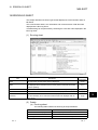
Precautions on setting MX Sheet
(1) Word designation for bit and bit designation for word
In the following tabs and dialog boxes, word designation for bit (e.g. K4M0) and
bit designation for word (e.g. D0.0) cannot be set.
1
1) <<Access Data>> tab *
2) <<Device Trigger>> Tab
3) <<Handshake>> tab
4) "Automatic Save" dialog box
5) "Automatic Print" dialog box
*1: When using MX Sheet Version 1.06 G or later, the device can be set by
means of bit designated for word device (e.g. D0.0).
(2) Reading character strings
When character strings are read from the PLC, the device data which prefix is
either of the following characters are not displayed normally on an Excel sheet.
When reading character strings from the PLC, make proper setting so that either
of the following characters will not be prefixed.
1) = (equal)
2) ' (single quotation)
(3) Save of Excel sheets
If the file name specified in the "Automatic Save" dialog box or "Operating when
cell is full" of the <<Use>> tab already exists, the old data is discarded and
overwritten.
Make proper setting so that the file name specified in the "Automatic Save" dialog
box or "Operating when cell is full" of the <<Use>> tab does not overlap those of
the other Excel books.
(4) Color designation
(a) Color designation
When using Excel 2003 or earlier and specifying any of the following colors
for "Set the Color of Grid line" or "Set the Color for Filling" on the <<Use>>
tab, the actual display color differs from the specified color.
(b) Color designation from Excel
If the line color and cell filling color have been specified from "Format Cells",
of Excel, the colors specified in "Set the Color of Grind line" and "Set the
Color for Filling" of the <<Use>> tab are made invalid.
A-6
A-6
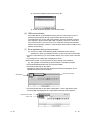
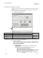
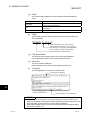
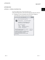
(c) Compatibility check
In Excel 2007 or later, when setting colors to a Book in Excel from 97 to 2003
on the
version with Cell Settings of MX Sheet, if specifying the color of
following screen, the Compatibility Checker screen appears on the Excel at
saving the Book.
< Compatibility Checker screen >
(5) Operation guarantee according to version
Due to the upgrade, the functions of the MX Sheet have been added/extended.
Operate the Excel book where MX Sheet functions are set with the MX Sheet
whose version is the same or later than the set MX Sheet for operation
guarantee.
For description of the added/extended functions, refer to APPENDIX 8.
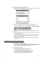
(6) Excel sheet where buttons are placed
When the Start Communication, End Communication or 1 Shot Communication
button placed on the Excel sheet is focused, do not log off from Windows or exit
from Windows without closing the Excel book.
To do so will display the following message and disable exit from Excel.
(7) Size of saved Excel file according to Format Cells
On Excel, Format Cells increases the saved file size.
Also on MX Sheet, the size of the saved Excel file may become several M bytes
or more since Format Cells is changed according to the setting.
(Example)
• When "Set the Color of Grid line" or "Set the Color of Filling" is checked on
the <<Use>> Tab
• When Logging is selected and "Add date and time details" is checked on
the <<Use>> Tab
• When Alarm Summary is selected on the <<Use>> Tab
• When "Character string" is specified as the Data Type on the <<Access
Data>> Tab
• When "HEX" is specified as the Value on the <<Access Data>> Tab
A-7
A-7
Precautions on editing cells and Excel sheets
(1) Save function
If either of the following settings has been made to the Excel book where the
ActiveX controls and forms have been applied, continuous operation of the
personal computer will cause insufficient memory.
If insufficient memory has occurred, shut down the personal computer
periodically.
• Save function of MX Sheet (automatic save function or save is performed
when cell is full)
• Save function is called in a VBA program.
Excel 2007 or later may require much time to save a Book than Excel 2003 or
earlier.
For expected time, refer to APPENDIX 3 (4).
(2) Changing of Excel sheet name
When changing the sheet name of the Excel sheet where MX Sheet has been
set, change it from [MX Sheet] [Change Sheet Name].
(It can also be changed from the toolbar (icons) or a right-click of the mouse.)
If the sheet name is changed directly from Excel or from a VBA program, MX
Sheet will not operate normally.
If this happens due to sheet name change, set the previous sheet name again.
(3) ErrorLog sheet
(a) Setting of sheet protection (workbook protection)
Do not set "Protect Sheet" and "Protect Workbook" to the ErrorLog sheet.
If such setting is made, the ErrorLog sheet will not operate normally.
(b) Sheet name
In the Excel book where MX Sheet has been set, do not give the name
"ErrorLog" to newly created worksheet, chart or dialog sheet.
If this happens, the ErrorLog sheet created by MX Sheet will not operate
normally.
(4) Application error occurring during use of Excel 2000
If an application error occurs at an exit from Excel 2000, check the symptoms
and corrective measures at the following URL site (as of July, 2002 *1).
http://www. microsoft. com/JAPAN/support/kb/articles/jp319/8/02.asp
Document number: JP319802
Title: [XL2000] Opening the file that has been sent using Outlook Express results
in a forced end at an exit from Excel
*1: The URL is valid as of July, 2002.
If the URL has been changed, confirm the above document number and title
and contact Microsoft Corporation.
A-8
A-8
Precautions on communication
(1) Communication between personal computer and PLC
When PLC device data are collected/written using MX Sheet, the communication
restrictions that apply to MX Component also occur between the personal
computer and PLC.
For the restrictions on communications between the personal computer and PLC,
refer to the MX Component Operating Manual.
(2) Preview setting of Excel
When starting the communication of MX Sheet, do not activate the preview
setting (print preview, etc.) of Excel.
If the communication of MX Sheet is started with the preview setting of Excel
active, a memory leak will occur.
(3) Simultaneous communication from multiple Excel books
Multiple Excel books where MX Sheet setting has been made cannot be started
on a single personal computer to make communication simultaneously.
(4) When communicating Excel book is double-started
Do not make a double start (restart) of the Excel book that is communicating
using MX Sheet.
If such operation is performed, the following dialog box appears.
Click No to interrupt a double start (restart).
(5) When logoff/shutdown is executed during communication
Do not log off or shut down the personal computer during usual communication
or 1 shot communication.
Log off or shut down the personal computer after terminating the communication
with the PLC and exiting from Excel.
If logoff or shutdown of the personal computer is executed during
communication, the following symptoms will be observed.
In this case, take corrective actions to restore the system.
(a) Symptom
When MX Sheet setting is made, only the frame of Excel is displayed.
(b) Corrective action
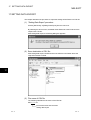
In the following procedure, remove the hide attributes of the Excel book and
overwrite the Excel book to restore the system.
1) Choose [Window] [Unhide] in the Excel menu.
A-9
A-9
2) Choose the hidden Excel book and click OK .
3) As the Excel book appears, save the Excel book.
(6) USB communication
If the USB cable is connected/disconnected, the PLC CPU is reset or PLC is
powered on/off frequently during communication with the PLC CPU, a
communication error occurs and communication cannot be returned to normal.
If this happens, disconnect the USB cable completely, leave it for 5 seconds or
more and reconnect it. (An error may occur at the time of initial communication
after the above operation, however, communication will be made normally at and
after the second time.)
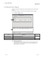
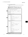
(7) Excel operation during communication
(a) If Excel is in either of the following status, MX Sheet cannot execute
operations on Excel (e.g. display into cells, or save or print of an Excel book).
• A cell is in input status (e.g. a cell is double-clicked, or the cursor is at the formula
bar).
• A message box or a dialog box is displayed on Excel.
Minimize the number of input processes on Excel during communications.
(b) The operation of Excel during communication is restricted as follows:
• Excel 2000/2002/2003 hides the menu bar and toolbar.
• Excel 2007 hides tabs on the ribbon.
Although the office button and the quick access toolbar are displayed, do not
operate them during communications.
Quick access toolbar
Office button
• Excel 2010 hides tabs on the ribbon. Although the <<File>> tab and the quick
access toolbar are displayed, do not operate them during communications.
Quick access toolbar
<<File>> tab
A - 10
A - 10
(8) Mouse cursor during communication
While MX Sheet is communicating, the mouse cursor setting of an Excel sheet is
fixed to the one of "Normal Select" in "Mouse Properties".
(9) Change to Design Mode of Excel during communication
For Excel during communication, do not change to the Design Mode using the
toolbar or similar means. To do so may disable normal operation of MX Sheet.
(10) Continuous operation when saving data automatically in HTML
format
Do not operate MX Sheet continuously when the Automatic save function is set
to save data in HTML format.
For operating MX Sheet continuously, exit and reactivate Excel periodically.
If data are saved repeatedly in HTML format with the Automatic save function,
Excel may not operate properly.
The time for allowable continuous operation differs according to the operating
environment.
Precautions on use of VBA
(1) Incorporation of VBA program
When incorporating a user-created VBA program into the Excel sheet where MX
Sheet has been set, check the operation of the VBA program first and then
perform MX Sheet programming for the Excel sheet.
(2) VBA program creation
MX Sheet utilizes OLE Automation for communication.
Do not perform the following on VBA programs.
1) Do not execute the DoEvents method in a For-Next loop.
2) FileFilter is ignored in the GetSaveAsFileName method.
3) Do not execute the Reset method in the Excel menu.
A - 11
A - 11
Precautions on use of other MELSOFT products
(1) MX Component version
MX Component Version 3.01B or later is required to use MX Sheet.
If MX Component Version 3.00A or earlier is used, MX Sheet does not operate
normally.
(2) Logical station number
Before deleting the logical station number from the Communication Setup Utility
of MX Component, check that the logical station number to be deleted is not
used in MX Sheet.
If the logical station number used in MX Sheet is deleted, MX Sheet does not
operate normally.
(3) Coexistence with MX Chart
MX Sheet and MX Chart cannot be installed in a single personal computer to
make communication simultaneously.
(4) Modem communication
When communication via modem is to be made by MX Sheet, MX Sheet, GX
Developer and other applications (e.g. user applications utilizing MX Component)
cannot perform communication simultaneously.
If simultaneous communication is attempted using MX Sheet, GX Developer and
other applications, a fault such as a communication error, telephone line
disconnection will occur.
When making communication via modem using MX Sheet, check that GX
Developer and other applications do not use modems.
A - 12
A - 12
INTRODUCTION
Thank you for choosing the Mitsubishi Integrated FA Software MELSOFT series.
Read this manual and make sure you understand the functions and performance of MELSOFT series
thoroughly in advance to ensure correct use.
CONTENTS
SAFETY PRECAUTIONS............................................................................................................................... A- 1
CONDITIONS OF USE FOR THE PRODUCT .............................................................................................. A- 2
REVISIONS ......................................................................................................................................................A- 3
Operating Precautions .....................................................................................................................................A- 5
CONTENTS......................................................................................................................................................A-13
Manuals ............................................................................................................................................................A-17
Generic Terms and Abbreviations ...................................................................................................................A-18
How to Use This Manual..................................................................................................................................A-19
Definitions of Terms ........................................................................................................................................A-20
Packing List ......................................................................................................................................................A-21
1 OVERVIEW
1- 1 to 1- 4
1.1 Features ..................................................................................................................................................... 1- 2
2 SYSTEM CONFIGURATION
2- 1 to 2- 2
2.1 Operating Environment.............................................................................................................................. 2- 1
3 FUNCTION LIST OF MX Sheet
3- 1 to 3- 2
3.1 Function List of MX Sheet.......................................................................................................................... 3- 1
3.2 Accessible CPUs and Accessible Device Ranges ................................................................................... 3- 2
4 MX Sheet OPERATION PROCEDURE
4- 1 to 4- 2
5 MX Sheet MENU SELECTION METHOD
5- 1 to 5- 2
6 CELL SETTING
6- 1 to 6-75
6.1 Operation of Cell Setting Dialog Box......................................................................................................... 6- 1
6.2 When Logging Is Selected......................................................................................................................... 6- 2
6.2.1 Setting of the Use tab.......................................................................................................................... 6- 3
6.2.2 Setting of the Access Data tab ........................................................................................................... 6-11
6.2.3 Setting of the Operation Interval tab................................................................................................... 6-16
6.2.4 Setting of the Device Trigger tab ........................................................................................................ 6-22
6.2.5 Setting of the Handshake tab ............................................................................................................. 6-25
6.2.6 Setting of the CSV Logging tab .......................................................................................................... 6-35
A - 13
A - 13
6.3 When Monitor Is Selected.......................................................................................................................... 6-38
6.3.1 Setting of the Use tab.......................................................................................................................... 6-39
6.3.2 Setting of the Access Data tab ........................................................................................................... 6-42
6.3.3 Setting of the Operation Interval tab................................................................................................... 6-43
6.3.4 Setting of the Device Trigger tab ........................................................................................................ 6-44
6.3.5 Setting of the Handshake tab ............................................................................................................. 6-45
6.3.6 Setting of the CSV Logging tab .......................................................................................................... 6-46
6.4 When Write Is Selected ............................................................................................................................. 6-47
6.4.1 Setting of the Use tab.......................................................................................................................... 6-48
6.4.2 Setting of the Access Data tab ........................................................................................................... 6-50
6.4.3 Setting of the Operation Interval tab................................................................................................... 6-52
6.4.4 Setting of the Device Trigger tab ........................................................................................................ 6-53
6.4.5 Setting of the Handshake tab ............................................................................................................. 6-54
6.5 When Alarm Summary Is Selected ........................................................................................................... 6-55
6.5.1 Setting of the Use tab.......................................................................................................................... 6-56
6.5.2 Setting of the Access Data tab ........................................................................................................... 6-59
6.5.3 Setting of the Alarm Data tab.............................................................................................................. 6-61
6.5.4 Setting of the Operation Interval tab................................................................................................... 6-63
6.5.5 Setting of the Device Trigger tab ........................................................................................................ 6-64
6.6 When Comment Is Selected...................................................................................................................... 6-65
6.6.1 Setting of the Use tab.......................................................................................................................... 6-66
6.6.2 Setting of the Access Data tab ........................................................................................................... 6-67
6.6.3 Setting of the Comment Data tab ....................................................................................................... 6-69
6.6.4 Setting of the Operation Interval tab................................................................................................... 6-72
6.6.5 Setting of the Device Trigger tab ........................................................................................................ 6-73
6.6.6 Setting of the Handshake tab ............................................................................................................. 6-74
7 AUTOMATIC SAVE SETTING
7- 1 to 7- 9
7.1 Operating of Automatic save list Dialog Box............................................................................................. 7- 1
7.2 Setting of the Automatic save Dialog Box ................................................................................................. 7- 4
8 AUTOMATIC PRINT SETTING
8- 1 to 8- 5
8.1 Operating of Automatic print list Dialog Box ............................................................................................. 8- 1
8.2 Setting of the Automatic print Dialog Box.................................................................................................. 8- 2
9 AUTOMATIC COMMUNICATION STARTUP SETTING
10 COMMUNICATION START AND COMMUNICATION END
9- 1 to 9- 2
10- 1 to 10- 3
10.1 Communication Start ............................................................................................................................. 10- 1
10.2 Communication End............................................................................................................................... 10- 3
11 1 SHOT COMMUNICATION
A - 14
11- 1 to 11- 2
A - 14
12 CELL EDITING
12- 1 to 12- 5
12.1 Cutting the Cell Area.............................................................................................................................. 1212.2 Copying the Cell Area ............................................................................................................................ 1212.3 Pasting the Cell Area ............................................................................................................................. 1212.4 Deleting the Cell Area ............................................................................................................................ 12-
1
2
3
5
13 CHANGING THE SHEET NAME
13- 1 to 13- 2
14 Create Button
14- 1 to 14- 7
14.1 Start Communication Button.................................................................................................................. 14- 1
14.2 End Communication Button................................................................................................................... 14- 6
14.3 1 Shot Communication Button............................................................................................................... 14- 7
15 Protect/Unprotect MX Sheet setting
15- 1 to 15- 4
15.1 Protect MX Sheet setting ....................................................................................................................... 15- 1
15.2 Unprotect MX Sheet setting................................................................................................................... 15- 4
16 Options
16- 1 to 16- 2
16.1 Setting of the error log ........................................................................................................................... 16- 1
17 SETTING DATA EXPORT
17- 1 to 17- 3
18 SAMPLE PROGRAMS
18- 1 to 18- 2
19 ERRORLOG SHEET
19- 1 to 19- 2
20 DATA CONVERSION FUNCTION
20- 1 to 20- 8
20.1 Data Conversion Function ..................................................................................................................... 2020.2 Operation Procedure of MXComShConv.exe....................................................................................... 2020.3 Conversion Log File ............................................................................................................................... 2020.4 Precautions on Excel Book after Data Conversion Function Execution .............................................. 20APPENDICES
1
3
5
6
APP-1 to APP-29
APPENDIX 1 VERSION CONFIRMATION................................................................................................APP- 1
APPENDIX 2 COMPARISON BETWEEN MX Sheet AND MX Chart ......................................................APP- 2
APPENDIX 3 PROCESSING SPEED OF MX Sheet ................................................................................APP- 3
A - 15
A - 15
APPENDIX 4 PROCESSING MX Sheet ....................................................................................................APP- 5
Appendix 4.1 Collection Delay and Data Dropout..................................................................................APP- 5
Appendix 4.2 Date and Time ..................................................................................................................APP- 9
APPENDIX 5 CREATING THE Excel SHEET FOR MX Sheet.................................................................APP-10
APPENDIX 6 PROCEDURE TO TRANSPORT DATA TO OTHER PERSONAL COMPUTER .............APP-13
APPENDIX 7 HTML FILE ...........................................................................................................................APP-14
APPENDIX 8 Warning Message Appears on Windows Vista and Windows 7.....................................APP-15
Appendix 8.1 Overview of warning message .........................................................................................APP-15
Appendix 8.2 Methods for preventing the warning message.................................................................APP-16
APPENDIX 9 ACTION FOR ERRORS OCCURRED WHEN Excel 2007 OR LATER FOR WHICH
AUTOMATIC COMMUNICATION STARTUP HAS BEEN SET IS OPENED ...................APP-21
APPENDIX 9.1 Situations .......................................................................................................................APP-21
APPENDIX 9.2 Error Cause ...................................................................................................................APP-21
APPENDIX 9.3 Corrective Action ...........................................................................................................APP-22
APPENDIX 10 ADDED/EXTENDED FUNCTIONS ...................................................................................APP-27
R
INDEX
A - 16
R
Index- 1 to Index- 2
A - 16
Manuals
The following manuals are relevant to for this software package.
Refer to the table when ordering the manuals.
Relevant Manuals
Manual Number
(Model Code)
Manual Name
MX Sheet Version 1 Operating Manual (Introduction)
Explains the installation method, function outlines and operation methods of MX Sheet Version 1.
(Sold separately)
(Sold separately)
SH-0800271
(13JU32)
(Sold separately)
SH-080272
(13JF66)
MX Component Version 3 Operating Manual
Explains the setting and operation methods of each utility on MX Component.
MX Component Version 3 Programming Manual
Explains the programming procedures, details and error codes for ACT control.
SH-080347E
(13JU34)
Note: The MX Sheet Version 1 Operating Manual (Introduction) is stored on CD-ROM of the corresponding
software package in PDF format.
Any of the manuals is available separately in printed form. Please indicate its manual number (model
code) in the above table, when ordering the printed manual.
A - 17
A - 17
Generic Terms and Abbreviations
Unless otherwise stated, this manual uses the following abbreviations and terms for
the explanation of MX Sheet.
Generic Term/Abbreviation
Description
Generic product name for product types SW1D5C-SHEET-E and SW1D5C-SHEET-EA.
MX Sheet
-EA indicates a volume license product.
IBM-PC/AT compatible
PC CPU module
Personal computer
MX Component
Abbreviation of the IBM PC/AT or its compatible personal computer.
Abbreviation of the MELSEC-Q series corresponding PC CPU module
(CONTEC CO., LTD.).
Generic term of PC CPU module and IBM-PC/AT compatible Personal computer.
Generic product name for product types SW3D5C-ACT-E and SW3D5C-ACT-EA.
-EA indicates a volume license product.
MX Links
Generic product name of the product type SW3D5F-CSKP-E.
MX Chart
Generic product name of the product type SW3D5F-OLEX-E.
R
R
R
R
R
R
R
R
R
R
Microsoft Windows 7 Starter Operating System,
Microsoft Windows 7 Home Premium Operating System,
Microsoft Windows 7 Professional Operating System,
Microsoft Windows 7 Ultimate Operating System and
R
Windows 7
Microsoft Windows 7 Enterprise Operating System.
R
Note that the 32-bit version is designated as "32-bit Windows 7", and the 64-bit version
R
is designated as "64-bit Windows 7".
R
Generic term of Microsoft Windows Vista
R
R
Home Premium Operating System,
R
R
Business Operating System,
R
R
Ultimate Operating System and
R
R
Enterprise Operating System.
Microsoft Windows Vista
Microsoft Windows Vista
Microsoft Windows Vista
R
R
Windows XP
A - 18
Home Basic Operating System,
R
Microsoft Windows Vista
Windows Vista
R
R
Generic term of Microsoft Windows XP Professional Operating System and
R
R
Microsoft Windows XP Home Edition Operating System.
A - 18
How to Use This Manual
This manual is organized with sections representing each aspect of MX Sheet.
Refer to the respective section when you need to know the following.
(1) The features (Section 1.1)
Section 1.1 gives the features.
(2) The system configuration and operating environment (Section 2.1)
Section 2.1 provides the operating environment.
(3) The functions, performance and applicable PLC CPUs of MX Sheet
(Sections 3.1 to 3.2)
Section 3.1 lists the functions of MX Sheet, and Section 3.2 gives information on
the applicable PLC CPUs.
(4) The operation procedure of MX Sheet (Chapter 4)
Chapter 4 provides the operation procedure of MX Sheet.
(5) The menu of MX Sheet (Chapter 5)
Chapter 5 describes the MX Sheet menu selection method.
(6) The cell setting methods of MX Sheet (Chapter 6)
Chapter 6 describes the MX Sheet cell setting methods.
(7) Automatic save setting (Chapter 7)
Chapter 7 describes the automatic save setting of each data.
(8) Automatic print setting (Chapter 8)
Chapter 8 describes the automatic print setting of each data.
(9) Automatic communication startup setting (Chapter 9)
Chapter 9 describes the automatic communication startup setting of each
function.
(10) Communication start and communication end (Chapter 10)
Chapter 10 describes communication start and communication end.
(11) 1 shot communication (Chapter 11)
Chapter 11 describes 1 shot communication.
(12) Cell editing (Chapter 12)
Chapter 12 describes cell editing (cutting, copying, pasting and deletion of cell
area).
(13) The sheet name changing method (Chapter 13)
Chapter 13 describes the sheet name changing method.
A - 19
A - 19
(14) Create Button (Chapter 14)
Chapter 14 describes the creation of the Start Communication, End
Communication, and 1 Shot Communication buttons.
(15) Protect/Unprotect MX Sheet setting (Chapter 15)
Chapter 15 describes Protect/Unprotect MX Sheet setting by password.
(16) Options (Chapter 16)
Chapter 16 describes Options for setting the output format of an error log sheet.
(17) The setting data export (Chapter 17)
Chapter 17 describes the setting data export.
(18) The error log checking method (Chapter 19)
Chapter 19 describes the error log checking method.
(19) The data utilization method of MX Chart (Chapter 20)
Chapter 20 describes the data utilization method of MX Chart.
(20) The version confirmation method (Appendix 1)
Appendix 1 describes the version confirmation method of MX Sheet.
Definitions of Terms
The terms used in this manual have the following meanings and definitions.
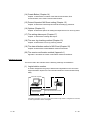
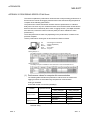
(1) Logical station number
A number assigned to the group of data that is integrated from the connection
target information required for communication within the Communication Setup
Utility.
Personal computer
Serial (COM1)
Q02HCPU
Baud rate transmission control
Time-out period
Connection information up to CPU of the communication target station is integrated into one data,
to which logical station number is assigned.
A - 20
A - 20
Packing List
The MX Sheet consists of the following products.
Type
Product Name
MX Sheet Version 1(1-license product)
SW1D5C-SHEET-E
(CD-ROM)
1
End-user software license agreement
1
License certificate
1
MX Sheet Version 1(Volume license product)
SW1D5C-SHEET-EA
Quantity
(CD-ROM)
End-user software license agreement
License certificate
1
1
n *1
*1: The number of included license agreements is equivalent to the number of licenses.
A - 21
A - 21
1 OVERVIEW
MELSOFT
1 OVERVIEW
1
MX Sheet is a communication support software package that allows device data
collection, etc. by simple, program-less setting using Excel.
Logging function, monitor function
Write function
Automatic print function
Alarm summary function
Comment display function
Automatic save function
MX Sheet
Excel book file
HTML file
CSV file
PLC CPU
1-1
1-1
1 OVERVIEW
MELSOFT
1.1 Features
1
This section explains the features of MX Sheet.
(1) Program-less and easy setting
PLC device data can be collected/written by making simple setting without
programming.
MX Sheet
Excel
Making
simple setting
PLC device data are displayed on Excel sheet.
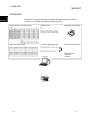
(2) Collection/write of device data using a wide range of
communication paths
MX Sheet uses MX Component for communication between the PLC and
personal computer.
Using a variety of communication paths supported by MX Component, system
configuration that meets user's requirement can be achieved.
<Examples of communication using MX Component>
Ethernet communication
MELSECNET/H communication
GOT
Modem communication
1-2
Gateway function communication
1-2
1 OVERVIEW
MELSOFT
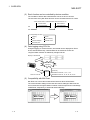
(3) Each function can be controlled by device condition.
The condition of device data collection/write can be set to PLC devices.
The execution of any MX Sheet function can be controlled from the PLC side.
<When device data is collected/written while bit device is on>
Device data is
collected/written
Device data is
collected/written
ON
OFF
Corresponding functions
Logging
Monitor
Write
Alarm summary
Comment display
Automatic save
Automatic print
(4) Data logging using CSV file
Using the logging or monitor function, device data can be displayed on Excel
sheet, and simultaneously, collected data can be saved into a CSV file.
Long-term data collection is enabled by a single CSV file.
Display on Excel sheet
Simultaneous
execution!
[CSV file]
2002/05/04 08:00:00, 0, 0, 0, 0, 0, 0
Save into CSV file
2002/05/04 08:00:10, 10, 20, 30, 40, 50, 60
(5) Compatibility with MX Chart
MX Sheet can convert the set data of MX Chart into those of MX Sheet.
The communication settings of MX Links and various settings of MX Chart can
be converted into the logical station numbers of MX Component and cell settings
of MX Sheet, respectively, to utilize old assets efficiently.
MX Chart
1-3
Conversion
MX Sheet
1-3
1 OVERVIEW
MELSOFT
(6) Improvement of operability by buttons
By creating buttons, the Start Communication, End Communication, and 1 Shot
Communication functions can be executed by merely clicking the corresponding
buttons.
Operability is improved as compared to the execution of the functions from the
menu.
(Example) Start Communication
After displaying the MX Sheet menu,
select the Start Communication.
Button
Click only
1-4
1-4
2 SYSTEM CONFIGURATION
MELSOFT
2 SYSTEM CONFIGURATION
The system configuration for MX Sheet is the same as that for MX Component Version 3.
For details, refer to the MX Component Version 3 Operating Manual.
2.1 Operating Environment
The following table indicates the operating environment of MX Sheet.
2
Item
Description
IBM PC/AT
Pentium 200MHz or higher *1 IBM PC/AT compatible personal computer installed with
compatible
2
applicable OS *
Computer
personal computer
R
PC CPU module
MELSEC-Q series compatible PC CPU module (CONTEC CO., LTD.)
4
Required memory
64MB or more *
Hard disk free space
100MB or more
Disk drive
CD-ROM disk drive
Display
1024 × 768 dot or higher resolution
System Software
Microsoft
Microsoft
Microsoft
Microsoft
Microsoft
Microsoft
Microsoft
Microsoft
Microsoft
Microsoft
Microsoft
Microsoft
Microsoft
Microsoft
Microsoft
Microsoft
R
R
R
R
R
R
R
R
R
R
R
R
R
R
R
R
Windows 98 Operating System (English version),
Windows Millennium Edition Operating System (English version),
3
Windows NT Workstation Operating System Version 4.0 (English version) * ,
Windows 2000 Professional Operating System (English version),
Windows XP Professional Operating System (English version),
Windows XP Home Edition Operating System (English version),
Windows Vista Home Basic Operating System (English version),
Windows Vista Home Premium Operating System (English version),
Windows Vista Business Operating System (English version),
Windows Vista Ultimate Operating System (English version),
Windows Vista Enterprise Operating System (English version),
Windows 7 Starter Operating System (English version),
Windows 7 Home Premium Operating System (English version),
Windows 7 Professional Operating System (English version),
Windows 7 Ultimate Operating System (English version) or
Windows 7 Enterprise Operating System (English version).
R
R
R
R
R
R
R
R
R
R
R
R
R
R
R
R
Microsoft Excel 2000 (English version), Microsoft Excel 2002 (English version),
6
Microsoft Excel 2003 (English version), Microsoft Excel 2007 (English version)* , or
7
32-bit Microsoft Excel 2010 (English version)*
R
Required
Software
5
Excel *
R
R
R
R
8
MX Component*
MX Component version 3.01B or later
*1: A Pentium 300MHz processor or higher is recommended for Windows XP Professional and Windows XP Home
Edition. 1GHz or higher is recommended for Windows Vista and Windows 7.
*2: This product does not work with a multiprocessor IBM-PC/AT-compatible personal computer, because the driver is not
compatible with it.
*3: Service Pack 3 or more is needed when using Windows NT Workstation 4.0.
*4: 128MB or more is recommended for Windows XP, 1GB or more is recommended for Windows Vista and 32-bit
Windows 7, and 2GB or more is recommended for 64-bit Windows 7.
*5: Excel sheets created in the English environment can be used in the English environment only. They cannot be used in
other environment.
R
*6: Windows XP Service Pack 2 or later is required for Excel 2007.
R
R
R
*7: For 32-bit Microsoft Excel 2010, Windows XP Service Pack 3, Windows Vista Service Pack 1 or higher, or
R
Windows 7 or later is required.
64-bit Microsoft Excel 2010 is not supported.
*8: When executing the Communication Setup Utility with administrator authority from Excel, MX Component Version
3.12N or later is required.
R
R
R
R
R
R
R
R
R
R
R
2-1
2-1
2 SYSTEM CONFIGURATION
MELSOFT
POINT
(1) When Windows XP Professional Operating System, Microsoft
Windows XP Home Edition Operating System, Windows Vista or
Windows 7 is used, the following new functions cannot be used.
If any of the following new functions is used, this product may not operate
normally.
Start of application in Windows compatible mode
Fast user switching
Remote desktop
Big fonts (Details setting of Screen properties).
64-bit Windows XP and 64-bit Windows Vista are not supported.
(2) When Windows 7 is used, the following new functions cannot be used.
Windows XP Mode
Windows Touch
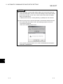
(3) When MX Sheet is tried to be installed on the personal computer where 64-bit
Microsoft Excel 2010 has been installed, the following error message appears.
R
R
R
R
R
R
R
R
R
R
(4) When MX Sheet is installed, 64-bit Microsoft Excel 2010 is installed and
started, then an add-in is installed, the following error message appears.
R
To use MX Sheet, install 32-bit Microsoft Excel 2010.
R
2-2
2-2
2
3 FUNCTION LIST OF MX Sheet
MELSOFT
3 FUNCTION LIST OF MX Sheet
This chapter describes the functions of MX Sheet, accessible CPUs and accessible
devices.
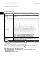
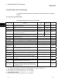
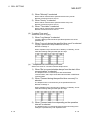
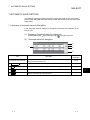
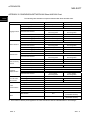
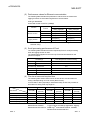
3.1 Function List of MX Sheet
The following table lists the functions of MX Sheet.
Function Name
3
Description
Logging
Accumulates device data collected from PLC in cell range
selected on Excel as history.
Monitor
Displays device data collected from PLC in cell range selected on
Excel.
Available Device
Points
Available Cells
Reference
Section
256 points *1, *2
256 columns
65536 rows
Section 6.2
2000 points *1, *3
2000
Section 6.3
2000
Section 6.4
1,
3
Write
Writes values entered on Excel to PLC devices.
2000 points * *
Alarm summary
Converts ON/OFF data of bit devices into alarm comment
character strings that are set separately and accumulates them
on Excel sheet as alarm history.
2000 points *2, *4
Comment display
Converts bit or word device values into comment character
strings that are set separately and displays them on Excel sheet.
Device trigger
Collects/Writes device data when set device conditions set for
collection/write are met.
----
Section 6.2.4
Handshake
Sets handshake with PLC for secure device data collection/write.
----
Section 6.2.5
CSV logging
Displays device data on Excel sheet with logging or monitor
function, and simultaneously saves collected data as a CSV file.
----
Section 6.2.6
Automatic save
Automatically saves Excel book
----
Chapter 7
Automatic print
Automatically prints Excel book.
----
Chapter 8
Automatic
communication
startup
Automatically starts communication with PLC when Excel book is
started.
----
Chapter 9
Communication
start
This function starts communication with the PLC.
----
Section 10.1
Communication
end
This function ends communication with the PLC.
----
Section 10.2
1 shot
communication
Executes functions set in the selected cell range at any desired
timing.
----
Chapter 11
Create Button
This function creates buttons to facilitate Start Communication,
End Communication, and 1 Shot Communication operations.
----
Chapter 14
Protect/Unprotect
MS Sheet setting
This function sets/cancels the password for protecting the MX
Sheet setting.
----
Chapter 15
Options
This function sets the output format of the error log sheet.
----
Chapter 16
Setting data
export
Outputs MX Sheet settings in CSV file format.
----
Chapter 17
Data conversion
Converts communication settings of MX Links (SW3D5FCSKPE) and various settings of MX Chart (SW3D5F-OLEXE)
into logical station numbers of MX Component and cell settings
of MX Sheet respectively.
----
Chapter 20
1 point *5
6 columns
65536 rows
1
Section 6.5
Section 6.6
*1: This number of device points refers to the case where word device data are collected/written in 16 bit integer.
The number of device points that can be set changes depending on the device data type, etc.
*2: One Excel file (one Excel book) accepts 100 - cell - area setting.
*3: One Excel file (one Excel book) accepts 1000 - cell - area setting.
*4: Only bit devices can be set.
*5: One Excel file (one Excel book) accepts 500 - cell - area setting.
3-1
3-1
3 FUNCTION LIST OF MX Sheet
MELSOFT
3.2 Accessible CPUs and Accessible Device Ranges
This section describes the accessible CPUs and accessible device ranges of MX
Sheet.
(1) Accessible CPUs
The accessible CPUs in MX Sheet are the same as those in MX Component
Version 3.
For details, refer to the MX Component Version 3 Operating Manual.
(2) Accessible device ranges
3
The accessible device ranges in MX Sheet are the same as those in MX
Component Version 3, with the exception of the following item.
For details, refer to the MX Component Version 3 Operating Manual.
1)
Device extension representation
MX Sheet does not allow access to any device by word designation for bit
device (e.g. K4X0, K8M0) and bit designation for word device (e.g. D0.0,
1
W.01).*
*1: When using MX Sheet Version1.06 G or later, device setting by bit
designation for word device (e.g. D0.0) is only possible in the setting on
<<Access Data >>tab.
(3) Specifying GOT timer contact devices and counter contact devices
In the cell settings of MX Sheet (Refer to Chapter 6), timer contact devices (TT)
and counter contact devices (CT) which are the device representation of GOT
can be entered.
The entered "TT" and "CT" are automatically changed to "TS" and "CS"
respectively.
3-2
3-2
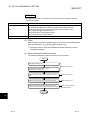
4 MX Sheet OPERATION PROCEDURE
MELSOFT
4 MX Sheet OPERATION PROCEDURE
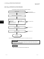
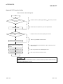
The following indicates the MX Sheet operation procedure.
Install MX Sheet.
Refer to the MX Sheet
Operating Manual (Introduction).
Start Excel and save the Excel book. *1
Select the function to be used, and make MX Sheet settings.
Logging function
Write function
Comment display function
Automatic print function
4
Monitor function
Alarm summary function
Automatic save function
Refer to Chapters 6 to 8.
Start communication.
Refer to Section 10.1.
End communication.
Refer to Section 10.2.
Completion
*1: Before starting MX Sheet settings, save the Excel book. If not, MX Sheet cannot be set.
POINT
Communication efficiency changes depending on the MX Sheet setting. Refer to
APPENDIX 3 and APPENDIX 5.
REMARK
Refer to the Excel manual for how to operate Excel.
4-1
4-1
4 MX Sheet OPERATION PROCEDURE
MELSOFT
<Administrator authority when setting/changing communication setup on
Windows Vista and Windows 7>
R
R
Administrator authority is required for setting/changing communication setup.
(1) Administrator authority in case of Windows Vista and Windows 7
1) When user account control (UAC) is enabled
R
R
All users including administrator are fixed at and operate as "standard
user".
To execute programs in administrator authority, specify "Run as
administrator".
* When executing Excel with administrator authority, even if selecting "NO"
for "Do you execute programs as an administrator?" executes with
administrator authority.
2)
When user account control (UAC) is disabled
4
Programs can be executed by login user.
(2) When setting/changing the communication setup on Windows
Vista and Windows 7
R
R
The following three methods are available to set/change the communication
setup.
• Execute Communication Setup Utility of MX Component with Administrator
authority and make setting/change the setting.
• Execute the Communication Setup Utility with administrator authority from
Excel for setting/changing.
• Execute Excel with Administrator authority and make setting/change the
setting.
* When executing Excel with administrator authority, the operations such
as opening the file by dragging and dropping cannot be executed.
4-2
4-2
5 MX Sheet MENU SELECTION METHOD
MELSOFT
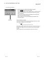
5 MX Sheet MENU SELECTION METHOD
MX Sheet can be operated from the menu bar, toolbar (icons) and right-click of the
mouse. When using Excel 2007 or later, operate from the ribbon.
This chapter describes the displaying method and details of the MX Sheet menu
options.
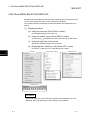
(1) Displaying method
(a) Using the menu bar (Excel 2003 or earlier)
Choose [MX Sheet] from the menu bar.
(b) Using the toolbar (icons) (Excel 2003 or earlier)
Choose [View]
[Toolbars] on the menu bar and click on "MX Sheet".
(c) Using the right-click of the mouse
Specify the cell area and right-click the mouse.
(d) Displaying the <<Add-Ins>> tab (Excel 2007 or later)
Choose the <<Add-Ins>> tab
Menu bar
5
[MX Sheet] on the ribbon.
Right-click of mouse
<<Add-Ins>> tab
Toolbar (Icons)
REMARK
If the Excel sheet type is other than the worksheet, the MX Sheet menu is not
displayed. When using MX Sheet, make setting on the worksheet.
5- 1
5-1
5 MX Sheet MENU SELECTION METHOD
MELSOFT
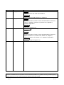
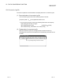
(2) MX Sheet menu details
The following table details the items of the MX Sheet menu.
Item
Menu bar
Icon
Right-click
Description
Reference
Section
Used to make cell
setting.
Chapter
6
----
Used to make automatic
save setting.
Chapter
7
----
Used to make automatic
print setting.
Chapter
8
----
Used to make automatic
communication startup
setting.
Chapter
9
----
Used to start
communication.
Section
10.1
----
Used to end
communication. *1
Section
10.2
Used to make 1 shot
communication.
Chapter
11
Used to cut a cell area
Section
12.1
Used to copy a cell area.
Section
12.2
Used to paste a cell
area. *2
Section
12.3
Used to delete a cell
area.
Section
12.4
Used to change the
Excel sheet name.
Chapter
13
Create the Start
Communication Button.
Create the End
Communication Button.
Create the 1 Shot
Communication Button.
Section
14.1
Section
14.2
Section
14.3
----
----
----
----
----
----
----
----
----
Protect the MX Sheet
setting.
Section
15.1
----
----
Unprotect the MX Sheet
setting.
Section
15.2
----
----
Set the error log options.
Section
16.1
----
----
Used to execute setting
data export.
Chapter
17
----
----
Used to display the MX
Sheet version.
Appendix
1
*1: Can be selected after start of communication.
*2: Can be selected after the cell area has been cut or copied.
5- 2
5-2
5
6 CELL SETTING
MELSOFT
6 CELL SETTING
This chapter describes cell setting required to operate MX Sheet.
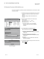
6.1 Operation of Cell Setting Dialog Box
This section explains the displaying procedure and setting item change of the "Cell
Setting" dialog box.
In the "Cell Setting" dialog box, its setting items change automatically depending on
the selected function.
(1) Displaying "Cell Setting" dialog box
Choose [MX Sheet]
[Cell Setting] (
) from the menu bar.
(2) Setting items of "Cell Setting" dialog box
The setting of the "Cell Setting" dialog box can be changed by selecting "Use" of
the <<Use>> tab.
Selecting "Use" changes setting items.
6
The following table indicates the function outlines and relevant sections for
options of "use".
Item
6-1
Function
Reference Section
Logging
Set when using the logging function.
Section 6.2
Monitor
Set when using the monitor function.
Section 6.3
Write
Set when using the write function.
Section 6.4
Alarm summary
Set when using the alarm summary function.
Section 6.5
Comment
Set when using the comment display function.
Section 6.6
6-1
6 CELL SETTING
MELSOFT
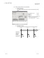
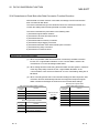
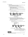
6.2 When Logging Is Selected
This section describes the "Cell Setting" dialog box when "Logging" is selected from
"Use" of the <<Use>> tab.
<<Use>> tab
<<Access Data>> tab
Required setting
Refer to Section
6.2.1.
<<Operation Interval>> tab
Required setting
Refer to Section
6.2.2.
<<Device Trigger>> tab
Set as necessary
Refer to Section
6.2.4.
Required setting
Refer to Section
6.2.3.
6
<<Handshake>> tab
<<CSV Logging>> tab
Set as necessary
Refer to Section
6.2.5.
6-2
Set as necessary
Refer to Section
6.2.6.
6-2
6 CELL SETTING
MELSOFT
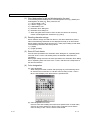
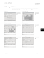
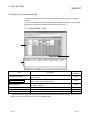
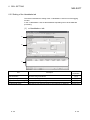
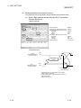
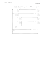
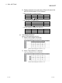
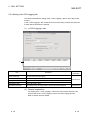
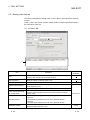
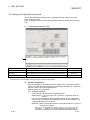
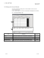
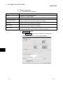
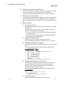
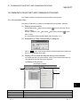
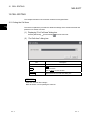
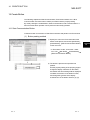
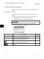
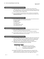
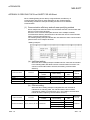
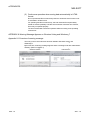
6.2.1 Setting of the Use tab
This section describes the setting of the <<Use>> tab for use of the logging function.
In the <<Use>> tab, set the cell area, logging data display position, displayed contents,
and operation when the cell is full.
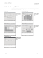
(1) <<Use>> tab
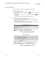
a)
Item
Detailed
Explanation
Description
Set the function to be used for the specified cell area. Choose "Logging"
when using the logging function.
Use
Cell Area Name
----
Set the name of the specified cell area.
----
(Maximum number of cell area names : 100)
Cell Area
Enter the value to specify the cell area.
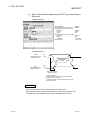
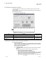
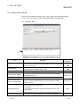
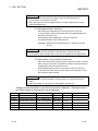
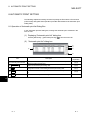
(2) (a)
Set the Color of Grid line
Set whether the specified cell area is provided with grid lines (including color
designation) or not.
(2) (b)
Set the Color for Filling
Set whether the specified cell area is colored or not.
When "Clear cell area at the start of communication" has a check mark, the
Clear cell area at the start
data in the cell area specified at the start of communication is cleared.
of communication
(Default: check)
(2) (c)
New data location
Set the latest data display position of the logging data.
• Last Line
The latest data is displayed at the lost of the specified cell area.
• First Line
The latest data is displayed at the first of the specified cell area.
(2) (d)
Displayed Contents
Set whether the title and the date and time are added to the displayed
logging data or not.
(2) (e)
(To the next page)
6-3
6-3
6 CELL SETTING
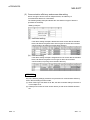
MELSOFT
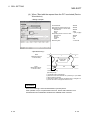
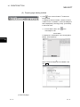
Item
Detailed
Explanation
Description
Set the operation to be performed when the specified cell area is full.
• To scroll
The displayed contents are scrolled and displayed.
• Display from the first without clearing the cell area
The data currently displayed in the cell area are overwritten and logging is
Operating when cell is full
resumed. Before logging is resumed, the Excel sheet can be printed and
saved.
• Display from the first after clearing the cell area
The data displayed in the cell area are erased and logging is resumed.
Before logging is resumed, the Excel sheet can be printed and saved.
(2) (f)
a) (Preset cell areas)
(2) (g)
The settings of the cell areas preset to the Excel book are displayed.
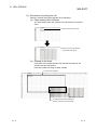
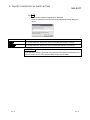
(2) Detailed explanation
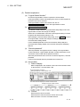
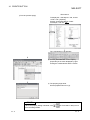
(a) "Cell Area"
Set the cell area to be used by the logging function.
1) Setting examples
<When a single cell range is specified (B2 to D5)>
B2 : D5
Enter the cell numbers with ":" in between.
Cell area from B2 to D5
(Number of cells : 12)
<When multiple cell areas are specified (B2 to D5 (Specified cell area 1) and B8 to D11 (Specified cell area 2))>
B2 : D5 , B8 : D11
Specified cell area 2
Enter the cell areas with "," in between.
Specified cell area 1
Specified cell area 1
(B2 to D5)
Specified cell areas 1 and 2
are displayed in this order.
In this case;
Number of specified cell area : 2
Number of cells : 24
Specified cell area 2
(B8 to D11)
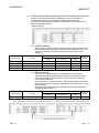
2) Setting ranges
The following indicates the available setting ranges for the cell area
and number of specified cell areas.
• Cell area
When date and time are added:
255 columns 65536 rows
When date and time are not added: 256 columns 65536 rows
• Number of specified cell areas: Up to 16
6-4
6-4
6 CELL SETTING
MELSOFT
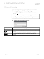
(b) "Set the Color of Grid line" and "Set the Color for Filling"
Set the colors of cell area grid lines and cell filling.
Depending on the selection, all area may be colored gray.
Refer to the Operating Precautions for details.
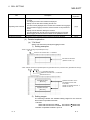
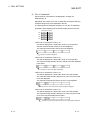
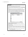
(c) "Clear cell area at the start of communication"
Set whether the cell area will be cleared or not at the start of
communication.
1) Display example in the case where "Clear cell area at the
start of communication" is checked
< Before the start of communication >
2004/05/24 Mon 13:00:00
2004/05/24 Mon 13:00:05
15
16
37
39
2004/05/24 Mon 13:00:10
17
42
< At the start of communication >
< At the completion of the first collection >
2004/05/24 Mon 15:00:00
31
102
2) Display example in the case where "Clear cell area at the
start of communication" is not checked
< Before the start of communication >
2004/05/24 Mon 13:00:00
15
37
2004/05/24 Mon 13:00:05
2004/05/24 Mon 13:00:10
16
17
39
42
2004/05/24 Mon 13:00:00
2004/05/24 Mon 13:00:05
15
16
37
39
2004/05/24 Mon 13:00:10
17
42
< At the start of communication >
< At the completion of the first collection >
6-5
2004/05/24 Mon 13:00:00
2004/05/24 Mon 13:00:05
15
16
37
39
2004/05/24 Mon 13:00:10
2004/05/24 Mon 15:00:00
17
31
42
102
6-5
6 CELL SETTING
MELSOFT
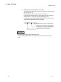
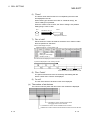
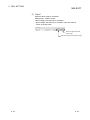
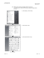
(d) "New data location"
Set the newest data location when the logging function is used.
1) When "Last Line" is selected
Old data
New data
2) When "First Line" is selected
New data
Old data
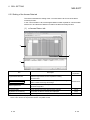
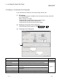
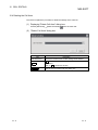
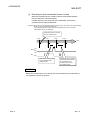
(e) "Displayed Contents"
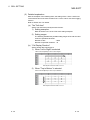
1) "Add title" check box
Set whether the date and time and the title for device name will be
displayed or not at the first line of the "Cell Area".
When displaying the title, check the check box.
<Display example>
When "Add date and time details" is checked and the devices D100
to D103 are set
The device name set on the <<Access Data>> tab is displayed.
Title
Collection data
Date Time
D100
D101
D102
D103
2004/05/24 Mon 13:24:14
30
100
0
37
2004/05/24 Mon 13:24:17
40
80
0
55
POINT
• The title display line will not be the target of cell area clear at the start of
communication or clear when cell is full.
• When the Cell Area is set at multiple locations, the title is displayed for only the
Cell Area specified first.
(Example) When the Cell Area on the <<Use>> tab is set to B2:E4, B6:E8
6-6
6-6
6 CELL SETTING
MELSOFT
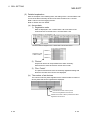
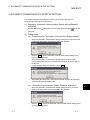
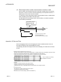
2) "Add date and time details" check box
Set whether the logging date and time are added to the cell area set in
the "Cell Area" or not.
When adding the date and time, check the check box.
In this case, the leftmost column of the logging data area is used for
the date and time. (One item of logging data decreases.)
The date and time column displays the date and time of the personal
computer where MX Sheet has been installed.
Indicates the time as "hours: minutes: seconds".
Indicates the day of the week as "Sun (Sunday),
Mon (Monday), Tue (Tuesday), Wed (Wednesday),
Thu (Thursday), Fri (Friday), Sat (Saturday)".
Indicates the date as "year/month/day".
REMARK
The above date and time can be edited on Excel.
If the cell setting is edited again after editing on Excel, the setting on Excel are
invalid.
6-7
6-7
6 CELL SETTING
MELSOFT
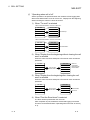
(f)
"Operating when cell is full"
Set the operation to be performed when the cell area is full of logging data.
When "New data location" is set for "First Line", "Display from the beginning
without clearing the cell area" cannot be chosen.
1) When "To scroll" is selected
<When "New data location" is set for "Last Line">
First data
Second data
Second data
Third data
Third data
Fourth data
Fourth data
Fifth data
Fifth data
Sixth data
Scrolled up.
<When "New data location" is set for "First Line">
Fifth data
Sixth data
Fourth data
Fifth data
Third data
Fourth data
Second data
Third data
First data
Second data
Scrolled down.
2) When "Display from the beginning without clearing the cell
area" is selected
When the cell is full, Excel sheet print or Excel book save can also be
performed.
First data
Sixth data
Second data
Second data
Third data
Fourth data
Print or save
Excel sheet.
Third data
Data are
overwritten,
beginning with
the first data.
Fourth data
Fifth data
Fifth data
3) When "Display from the beginning after clearing the cell
area" is selected
When the cell is full, Excel sheet print or Excel book save can also be
performed.
Sixth data
First data
Second data
Third data
Fourth data
Print or save
Excel sheet.
Erased when
cell is full.
Fifth data
4) When "Print the Excel sheet" is selected
The Excel sheet is printed when the cell is full.
After completion of print, all data are erased and logging is resumed.
This item can be selected when "Operating when cell is full" is set to 2)
or 3).
6-8
6-8
6 CELL SETTING
MELSOFT
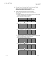
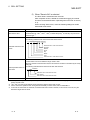
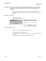
5) When "Save to file" is selected
The Excel book is saved when the cell is full.
After completion of save, all data are erased and logging is resumed.
This item can be selected when "Operating when cell is full" is set to 2)
or 3).
When choosing "Save to file", make the following settings for the file
where data will be saved.
Item
File name to save
Description
The storage location and file name is set for the Excel book to be saved when the cell is full. *
2
2
2
3
The Excel file (.xls, .xlsx* , .xlsm* , .xlsb* ) or HTML file (.htm)* or CSV file (.csv) can be set
4
as the file type. *
1
The file set in "File name to save" saves data with the date and time added to its file name.
The following indicates a file name format when data is saved.
*****20020523183536. extension
Extension set to "File name to save"
Seconds
Minutes
Hours
Day
Month
Year
File name set in "File name to save"
Add date and time to File
name
Add sequential number to
File name
The file set in "File name to save" saves data with a number added to its file name.
A serial number can be set within the range of 000 to 999.
When the number is reached to the last, the file of the first number is overwritten by the newly
saving file.
The following indicates the file name format when data is saved.
*****000. extension
Extension set in "File name to save"
File number
File name set in "File name to save"
Fix the File name
The file set in "File name to save" is overwritten by data.
*1: A UNC path name (\\server name\path name) cannot be specified as a file name. After assigning the network drive,
specify the path name.
*2: .xlsx, .xlsm, and .xlsb are Workbook-format extensions added to Excel 2007 or later.
*3: For the continuous operation when saving data automatically in HTML format, refer to APPENDIX 7.
*4: In the case of an Excel file or HTML file, the whole Excel book is saved. However, in the case of a CSV file, only the
data of the target sheet is saved.
6-9
6-9
6 CELL SETTING
MELSOFT
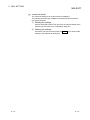
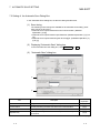
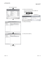
(g) "preset cell areas"
The cell areas already set to the Excel book are displayed.
The following operations are available by selecting the cell area name in
the "preset cell areas".
1) Reading the settings
Choose and double-click the cell area name to read the settings of the
selected cell area name to the "Cell Setting" dialog box.
2) Deleting the settings
Choose the cell area name and press the Delete key to erase all the
settings of the selected cell area name.
6 - 10
6 - 10
6 CELL SETTING
MELSOFT
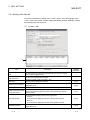
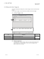
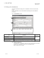
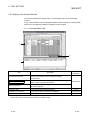
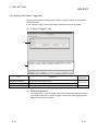
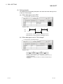
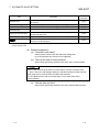
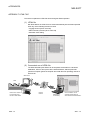
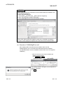
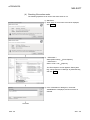
6.2.2 Setting of the Access Data tab
This section describes the setting of the <<Access Data>> tab for use of the logging
function.
In the <<Access Data>> tab, set the logical station number required for communication
with the PLC and the device data to be collected in the cell area.
(1) <<Access Data >> tab
a)
b)
c)
Item
Description
Detailed
Explanation
Select the logical station number required for making
communication.
(2) (a)
Used to start the Communication Setup Utility to set a new logical
station number and change the settings.
(2) (b)
Remote password *1
Enter the password when the password has been set to the
connection target PLC.
(2) (c)
a) (Access data)
Set the devices to be logged.
(2) (d)
b) (Number of set devices)
The number of devices currently set is displayed.
c) (Preset cell areas)
The settings of the cell areas preset to the Excel book are displayed.
Logical Station Number
Communication settings
(2) (e)
Section 6.2.1
*1: "Remote password" is displayed when the logical station number selected in "Logical Station Number" of the <<Access
Data>> tab is the one for the password function compatible module.
6 - 11
6 - 11
6 CELL SETTING
MELSOFT
(2) Detailed explanation
(a) "Logical Station Number"
Choose the logical station number required for communication.
If the logical station number has already been set, the number appears in
the list box and can be selected.
If the logical station number has not been set, click on
Communication Settings and set a new logical station number.
(b)
Communication settings
This button is used to start the Communication Setup Utility to set a new
logical station number and change the settings.
Select "Run as administrator" when the screen appears asking if execute
programs with administrator authority or not.
After starting the Communication Setup Utility, click on Wizard and set a
new logical station number and change the settings with the
Communication Setting Wizard.
For the detailed explanation of the Communication Setup Utility and
Communication Setting Wizard, refer to the MX Component Operating
Manual.
(c) "Remote password"
"Remote password" box appears when the setting of the logical station
number selected in "Logical Station Number" includes information on the
connection to the module with the password function.
When the password has been set to the connection target PLC, enter the
password.
It need not be entered when the password has not been set.
(d) Access data
1) Order of display
Data are displayed in the cell area in the order of the numbers shown
on the left of the <<Access Data>> tab.
<Device data display example>
Setting example of <<Access Data>> tab
Data numbers
The device data are displayed on Excel as shown below.
Displayed in order of data numbers.
Data No. 1
Data No. 2
Data No. 3
2) "Device"
Enter the device to be accessed.
Enter the device name and device number in this order.
Refer to Section 3.2 for the accessible devices.
6 - 12
6 - 12
6 CELL SETTING
MELSOFT
3) "Data Type"
Set the data type to be displayed in the cell.
Item
Available Device
Description
Bit device
The bit devices set in "Device" are displayed in a single cell in units
of one bit.
Word device
(Bit specification)
Designated bits for word device set in "Device" are displayed in a
single cell in units of one bit (e.g. D0.0).
Bit device
Displayed in a single cell in units of 1 word (16 bits), starting with the
1
device number set in "Device". *
Word device
Displayed in a single cell in units of 1 word, starting with the device
1
number set in "Device". *
32 bit integer
Bit device
(-2147483648 to
2147483647)
Displayed in a single cell in units of 2 words (32 bits), starting with
1
the device number set in "Device". *
Word device
Displayed in a single cell in units of 2 words, starting with the device
1
number set in "Device". *
Bit device
The data of the device number set in "Device" are displayed in the
2
cell as character strings. *
Word device
The data of the device number set in "Device" are displayed in the
2
cell as character strings. *
Bit device
Displayed in a single cell in units of 2 words (32 bits), starting with
1
the device number set in "Device". *
Word device
Displayed in a single cell in units of 2 words, starting with the device
1
number set in "Device". *
Bit
16 bit integer
(-32768 to 32767)
Character string
Real number
(
-126
2
|value|
128
2
, 0)
*1: The displayed value changes depending on the "Zoom" setting.
Refer to 6) for details.
*2: The unit and the number of displayed characters of the read data change depending on the "No. of characters" setting.
Refer to 5) for details.
4) "Value"
Select the display format of the value to be displayed in the cell from
DEC and HEX.
Depending on the "Data Type", the "Value" and "Zoom" can be
selected/set as described below.
Item
Data Type
Bit
Cell data display
Zoom
Cannot be selected
Cannot be set
0 or 1
DEC
Can be set
Displayed in decimal
HEX
Cannot be set
Display in 4-digit hexadecimal (ex. 03EB)
DEC
Can be set
Displayed in decimal
HEX
Cannot be set
Display in 8-digit hexadecimal
(ex. 03EB03EA)
Character String
Cannot be selected
Cannot be set
Character string is displayed (ex. ABCD)
Real number
Cannot be selected
Can be set
Real number is displayed (ex. 1.36E-36)
16 bit integer
32 bit integer
6 - 13
Value
6 - 13
6 CELL SETTING
MELSOFT
5) "No. of characters"
Set the number of characters to be displayed in a single cell.
Setting range: 40
Depending on the value set in "No. of characters" and device data, the
character strings may not be displayed in the cell.
The following are the examples of setting 1 to 4 in "No. of characters".
(Example) When displaying the character strings stored in D0 to D3
D0
b15 to b8 b7 to b0
B
A
D1
D
C
D2
F
E
D3
H
G
<When "No. of characters" is set to "1">
The data is displayed in a single cell in units of 1 word (16 bits).
Only the character stored in b0 to b7 of D0 is displayed.
The character stored in b8 to b15 of D0 is not displayed.
D0 (b0 to b7) data is displayed.
<When "No. of characters" is set to "2">
The data is displayed in a single cell in units of 1 word (16 bits).
The character strings stored in b0 to b7 and b8 to b15 are displayed
in this order.
D0 (b0 to b7, b8 to b15) data is displayed.
<When "No. of characters" is set to "3">
The data is displayed in a single cell in units of 2 words (32 bits).
The character strings stored in D0 (b0 to b7, b8 to b15) and D1 (b0
to b7) are displayed.
The character string stored in b8 to b15 of D1 is not displayed.
D0 (b0 to b7, b8 to b15) and D1 (b0 to b7) data is displayed.
<When "No. of characters" is set to "4">
The data is displayed in a single cell in units of 2 words (32 bits).
The character strings stored in D0 (b0 to b7, b8 to b15) and D1 (b0
to b7, b8 to b15) are displayed in this order.
D0 (b0 to b7, b8 to b15) and D1 (b0 to b7, b8 to b15) data is displayed.
6 - 14
6 - 14
6 CELL SETTING
MELSOFT
6) "Zoom"
The device value read from the PLC is multiplied by the zoom ratio
and displayed in the cell.
When "Data Type" has been set to "Bit" or "Character string", the
"Zoom" setting is not possible.
When the "Value" is set to "HEX", the "Zoom" setting is not possible.
Setting range: 0.001 to 1000
PLC
Set "Zoom" to "0.1".
Excel
D0
25
Displayed 2.5 on Excel.
7) "No. of cells"
Set the number of cells to be used for the device set in "Device" within
the area specified in "Cell Area".
<Device data display example>
Setting example of <<Access Data>> tab
Device: D0
Data type: 16 bit integer
Number of cells: 3
The device data are displayed on Excel as shown below.
3 points are displayed in order, starting with D0.
These are set as the cell area but not used.
8) "Dev. Points"
The points of the devices to be consecutively read starting with the
device number set in "Device" are displayed.
9) "In unit"
The unit of the device to be shown in the cell is displayed.
(e) The number of set devices
The number of device points and others set to the cell area are displayed.
Indicates the number of device points set for
the logging function in the cell area.
Indicates the number of cells available for the cell area.
Indicates the number of cells where the device has been set in the cell area.
6 - 15
6 - 15
6 CELL SETTING
MELSOFT
6.2.3 Setting of the Operation Interval tab
This section describes the setting of the <<Operation Interval>> tab for use of the
logging function.
In the <<Operation Interval>> tab, set the day, time and time zone of the activation of
the function for the cell area.
(1) <<Operation Interval>> tab
a)
Item
Detailed
Explanation
Description
Set the Operation Interval
Set the operation of the cell area valid or invalid.
(2) (a)
Operation day
Set the operation day of the logging activation.
(2) (b)
Operation time
Set the operation time of the logging activation.
(2) (c)
Logging Time zone *1
Set the time zone of the logging activation.
(2) (d)
a) (Preset cell areas)
The settings of the cell areas preset to the Excel book are displayed.
Section 6.2.1
*1: If the logical station number selected in "Logical Station Number" of the <<Access Data>> tab is the one for modem
communication, "Logging Time zone" is switched to "Telephone line connectivity time zone".
Item
Telephone line
connectivity
time zone
6 - 16
Description
Sets the timing of
connection and
disconnection of the
telephone line.
Detailed
Explanation
(2) (e)
6 - 16
6 CELL SETTING
MELSOFT
(2) Detailed explanation
(a) "Set the Operation Interval"
To make the settings of cell area invalid or to use the function of cell area
for 1 shot communication only, remove the check mark. (Do not remove
the check mark for the case of ordinary operation.)
(b) "Operation day"
Set the operation day of device data collection.
1) When "Daily" is selected
Operation is performed every day.
2) When "Weekly" is selected
Operation is performed on the specified day of the week only.
Multiple days of the week can be set.
3) When "Monthly" is selected
Operation is performed on the specified days only.
If the specified day does not exist in some months, an alternate day
can be specified.
Number of days that can be set: 31
<When "15th" is set>
Operation is performed on the 15th every month, e.g. January 15,
February 15, March 15.
<When "31st" is set>
Excepting February, April, June, September and November,
operation is performed on the 31st every month.
For February, April, June, September and November, set the
alternate day and processing in "Alternate day when a date does
not exist".
The following table indicates the setting items of "Alternate day
when a date does not exist".
Item
Last day of the current month
First day of the next month
No operation
Description
Operation is performed on the last day of February, April, June, September or November.
Operation is performed on the first day of the next month.
Operation is not performed in February, April, June, September and November.
(c) "Operation time"
Set the operation time of device data collection.
1) When "Regular interval" is selected
Device data is collected at the set second intervals.
When modem communication is used and "Connect each time
depending " is set in "Telephone line ", set 30 seconds or more to
"Regular interval".
Setting range: 0.1 to 0.9 (in units of 0.1 seconds),
1 to 3600 (in units of 1 second)
When the date and time are added, the date and time displayed on the
Excel sheet will be in the "yyyy/mm/dd ddd hh:mm:ss" format if the
setting is 0.1 to 0.9 seconds.
(Example) When 0.2 seconds interval is set
6 - 17
6 - 17
6 CELL SETTING
MELSOFT
2) When "Minutely" is selected
Device data is collected at the specified second every minute.
Number of times that can be set: 60
3) When "Hourly" is selected
Device data is collected at the specified minute every hour.
Number of times that can be set: 60
4) When "Time table" is selected
Device data is collected at the specified time.
Number of times that can be set: 50
(d) "Logging Time zone"
Set the time zone for logging.
1) When "Log Always" is selected
Logging is always performed at the specified operation time of the
operation day.
2) When "Log only during the specified time zone" is selected
Logging is performed in the specified time zone only.
Number of settings: 4
When "Operation day" has been set to "Weekly" or "Monthly", do not
make the following setting that will span two days.
(e) "Telephone line connectivity time zone"
Set the time zone for connection with the telephone line.
1) When "Be in connected state always from the start of the
communication" is selected
The telephone line is connected upon start of MX Sheet
communication, and is kept connected until termination of MX Sheet
communication.
2) When "Connect during the specified time zone only" is
selected
The telephone line is connected only in the specified time zone.
Number of settings: 4
When "Operation day" has been set to "Weekly" or "Monthly", do not
make the following setting that will span two days.
3) When "Connect each time depending on the operation
interval" is selected
The telephone line is connected and disconnected according to the
settings of "Operation day" and "Operation time".
6 - 18
6 - 18
6 CELL SETTING
MELSOFT
(3) Setting examples
(a) When using communication other than modem communication
(Log Always)
1) Setting example
The following setting example shows that logging is always performed
at regular intervals.
Set the Operation Interval : Marked
Operation day
Daily
: Marked
Operation time
Regular interval
: 60 seconds
Logging Time zone
Log Always
: Marked
2) Operation timing
The following shows the operation timings in the setting example.
First
Second
60s
Third
60s
Fourth
60s
Fifth
60s
Sixth
60s
Time
Device data collection
is executed.
6 - 19
6 - 19
6 CELL SETTING
MELSOFT
(b) When using communication other than modem communication
(Log only during the specified time zone)
1) Setting example
The following setting example shows that logging is performed in the
specified time zone only.
Set the Operation Interval
: Marked
Operation day
Weekly
: Marked
Friday
: Marked
Operation time
Hourly
: 0 (minutes)
Logging Time zone
Log only during the specified time zone: Marked
Time zone
: 10:00 to 13:00
2) Operation timing
The following shows the operation timing in the setting example.
Every Friday
9:00
10:00
11:00
12:00
13:00
14:00
Time
Device data collection is executed.
Device data collection is not executed.
6 - 20
6 - 20
6 CELL SETTING
MELSOFT
(c) When using modem communication
1) Setting example
The setting example in the case of modem communication is shown
below.
Set the Operation Interval
: Marked
Operation day
Daily
: Marked
Operation time
Hourly
: 0 (minutes)
Telephone line connectivity time zone
Connect each time depending
: Marked
on the operation interval
2) Operation timing
The following shows the operation timing in the setting example.
9:00
10:00
11:00
Time
Connection of
telephone line
Device data
collection is
executed.
Disconnection of
telephone line
6 - 21
6 - 21
6 CELL SETTING
MELSOFT
6.2.4 Setting of the Device Trigger tab
This section describes the setting of the <<Device Trigger>> tab for use of the logging
function.
In the <<Device Trigger>> tab, set the device conditions for the device trigger.
(1) <<Device Trigger>> tab
a)
b)
Item
Description
Set the Device Trigger
Set when the device trigger is used.
a) (Device conditions)
Set the device conditions.
b) (Preset cell areas)
The settings of the cell areas preset to the Excel book are displayed.
6 - 22
Detailed
Explanation
(2) (a)
(2) (b)
Section 6.2.1
6 - 22
6 CELL SETTING
MELSOFT
(2) Detailed explanation
(a) "Set the Device Trigger"
When using the device trigger, be sure to mark "Set the Device Trigger".
(b) Device conditions
Set the device conditions for the device trigger.
1) Device type
Set the type of the device used for the device trigger.
Item
Description
Bit Device
Set when using a bit device for the device trigger.
Word Device
Set when using a word device for the device trigger.
2) "Device"
Enter the device used for the device trigger.
Enter the device name and device number in this order.
3) "the bit"
Set the corresponding bit of the word device.
Setting range: 0 to 15
4) "Condition"
Set the device trigger condition.
Item
When ON
ON
Available Device
Bit device
OFF
Word device
When OFF
Bit device
ON
Description
Set when operation is to be performed only once when the bit device
turns on.
Set when operation is to be performed only once when the
corresponding bit of the word device turns on (value: 1).
Set when operation is to be performed only once when the bit device
turns off.
Set when operation is to be performed only once when the
corresponding bit of the word device turns off (value: 0).
OFF
Word device
ON
Bit device
Set when operation is to be performed while the bit device is on.
Word device
Set when operation is to be performed while the corresponding bit of
the word device is on (value: 1).
Bit device
Set when operation is to be performed while the bit device is off.
ON
OFF
OFF
ON
OFF
Word device
=
Word device
<>
Word device
<=
Word device
<
Word device
>=
Word device
>
Word device
Range
Word device
6 - 23
Set when operation is to be performed while the corresponding bit of
the word device is off (value: 0).
Set when operation is to be performed when the device value is equal
to the "Value" setting.
Set when operation is to be performed when the device value is not
equal to the "Value" setting.
Set when operation is to be performed when the device value is equal
to or less than the "Value" setting.
Set when operation is to be performed when the device value is less
than the "Value" setting.
Set when operation is to be performed when the device value is equal
to or greater than the "Value" setting.
Set when operation is to be performed when the device value is
greater than the "Value" setting.
Set when operation is to be performed when the device value is within
the specified "Value" setting range.
6 - 23
6 CELL SETTING
MELSOFT
5) "Value"
Enter the values used for "Condition".
Setting range: -32768 to 32767
<When "Range" has been set in "Condition">
When "Range" has been set in "Condition", enter the values in
"Value" as shown below.
Enter the upper limit value
of the range.
Enter the lower limit value of the range.
6 - 24
6 - 24
6 CELL SETTING
MELSOFT
6.2.5 Setting of the Handshake tab
This section describes the setting of the <<Handshake>> tab for use of the logging
function.
In the <<Handshake>> tab, set the handshake requesting source and handshake
processing.
(1) <<Handshake>> tab
a)
b)
c)
Item
Description
Detailed
Explanation
Set Handshake
Set when using a handshake.
(3) (a)
a) (Requesting source setting)
Set the requesting source of the handshake.
(3) (b)
b) (Handshake processing)
Set the handshake processing.
(3) (c)
c) (Preset cell areas)
The settings of the cell areas preset to the Excel book are displayed.
6 - 25
Section 6.2.1
6 - 25
6 CELL SETTING
MELSOFT
(2) Setting examples and operation timing
The following shows the handshake setting examples and operation timing.
(a) When "Start with the request from the PLC" is selected
(Device: Bit device)
<Setting example>
Set Handshake
Start with the request from the PLC
Responding device on the PC side
Bit device
Device
Value
Requesting device on the PLC side
Bit device
Device
Condition
Monitoring time
: Marked
: Marked
: Marked
: M100
: ON
: Marked
: M0
: When ON
: 10 seconds
<Operation timing>
M100
(Responding device
on the PC side)
ON
3)
OFF
5)
2)
Device data
collection
M0
(Requesting device
on the PLC side)
ON
OFF
4)
1)
Time-out monitoring
(Monitoring time)
1) When M0 turns on, processing in 2) is started.
2) Device data is collected.
3) After device data is collected, M100 is turned on.
4) M0 is turned off.
5) M100 is turned off.
6 - 26
6 - 26
6 CELL SETTING
MELSOFT
(b) When "Start with the request from the PLC" is selected
(Device: Word device)
<Setting example>
Set Handshake
: Marked
Start with the request from the PLC : Marked
Responding device on the PC side
Word device
: Marked
Device
: D200
Value
: 1 (left), 0 (right)
Requesting device on the PLC side
Word device
: Marked
Device
: D100
Condition
:=
Value
: 100
Monitoring time
: 10 seconds
<Operation timing>
3)
D200
(Responding device
on the PC side)
5)
1
0
2)
Device data
collection
D100
(Requesting device
on the PLC side)
1)
4)
100
Time-out monitoring
(Monitoring time)
1) When the D100 value reaches 100, processing in 2) is started.
2) Device data is collected.
3) After device data is collected, the D200 value is changed to 1.
4) The D100 value is changed to other than 100.
5) The D200 value is changed to 0.
6 - 27
6 - 27
6 CELL SETTING
MELSOFT
(c) When "Start with the request from the PC" is selected (Device:
Bit device)
<Setting example>
Set Handshake
Start with the request from the PC
Requesting device on the PC side
Bit device
Device
Value
Responding device on the PLC side
Bit device
Device
Condition
Monitoring time
: Marked
: Marked
: Marked
: M100
: ON
: Marked
: M0
: When ON
: 10 seconds
<Operation timing>
M100
(Requesting device
on the PC side)
ON
OFF
4)
1)
3)
Device data
collection
M0
(Responding device
on the PLC side)
ON
2)
5)
OFF
Time-out monitoring
(Monitoring time)
1) M100 is turned on.
2) When M0 turns on, processing in 3) is started.
3) Device data is collected.
4) After device data is collected, M100 is turned off.
5) M0 is turned off.
REMARK
Time-out monitoring is not executed between 4) and 5) above.
If the operation in 5) is not performed in the PLC, device data collection is not
executed when the handshake conditions are satisfied at the next time.
6 - 28
6 - 28
6 CELL SETTING
MELSOFT
(d) When "Start with the request from the PC" is selected (Device:
Word device)
<Setting example>
Set Handshake
Start with the request from the PC
Requesting device on the PC side
Word device
Device
Value
Responding device on the PLC side
Word device
Device
Condition
Value
Monitoring time
: Marked
: Marked
: Marked
: D200
: 1 (left), 0 (right)
: Marked
: D100
:=
: 100
: 10 seconds
<Operation timing>
D200
(Requesting device
on the PC side)
1)
4)
1
0
3)
Device data
collection
D100
(Responding device
on the PLC side)
5)
2)
100
Time-out monitoring
(Monitoring time)
1) The D200 value is changed to 1.
2) When the D100 value reaches 100, processing in 3) is started.
3) Device data is collected.
4) After device data is collected, the D200 value is changed to 0.
5) The D100 value is changed to other than 100.
REMARK
Time-out monitoring is not executed between 4) and 5) above.
If the operation in 5) is not performed in the PLC, device data collection is not
executed when the handshake conditions are satisfied at the next time.
6 - 29
6 - 29
6 CELL SETTING
MELSOFT
(3) Detailed explanation
(a) "Set Handshake"
When using a handshake, be sure to mark "Set Handshake".
(b) Requesting source setting
Set the requesting source for a device data collection start.
Item
Description
Start with the request Set when starting device data collection at the request of
from the PLC
the PLC.
Start with the request Set when starting device data collection at the request of
from the PC
the personal computer.
(c) Handshake processing
Set the handshake processing on the personal computer side and PLC
side.
1) PC side processing
• Device type
Set the device type used for PC side processing.
Item
Description
Bit device
Set when a bit device is used for PC side processing.
Word device
Set when a word device is used for PC side processing.
• "Device"
Enter the device used for PC side processing.
Enter the device name and device number in this order.
When specifying a bit of the word device, enter the bit number in "the
bit".
• "Value"
Set the value of the device used for PC side processing.
Item
6 - 30
Available Device
Description
Bit device
ON
Set when the value of the device used for PC side
Word device (Bit specification) processing is set for ON.
OFF
Bit device
Set when the value of the device used for PC side
Word device (Bit specification) processing is set for OFF.
Empty (Value input)
Word device
Set the value of the word device used for PC side
processing.
6 - 30
6 CELL SETTING
MELSOFT
2) PLC side processing
• Device type
Set the device type used for PLC side processing.
Item
Description
Bit device
Set when a bit device is used for PLC side processing.
Word device
Set when a word device is used for PLC side processing.
• "Device"
Enter the device used for PLC side processing.
Enter the device name and device number in this order.
When specifying the bit use of the word device, enter the bit number
in "the bit".
• "Condition"
Set the conditions of the device used for PLC side processing.
Item
Available Device
Bit device
ON
Word device
(Bit specification)
Bit device
OFF
Word device
(Bit specification)
=
Word device
Description
Set when the value of the device used for PLC side
processing is set for ON.
Set when the value of the device used for PLC side
processing is set for OFF.
Set when the PLC side device value is equal to the "Value"
setting.
• "Value"
Set the value of the device used for PLC side processing.
This can be set only when "=" has been selected in "Condition".
3) Monitoring time
Set the time during which the PC side device monitors the PLC side
device.
Setting range: 1 to 3600
The monitoring time changes depending on the requesting source
setting.
The following table indicates the monitoring time.
Requesting Source Setting
6 - 31
Monitoring time
Start with the request from the
PLC
Monitoring is executed from the time when the PC side
responding device is set to the time when the PLC side
requesting device is reset. If the PLC side responding device
is not reset after the elapse of the monitoring time, the
collected device data is discarded and the error log is
displayed in the ErrorLog sheet.
Start with the request from the
PC
Monitoring is executed from the time when the PC side
requesting device is set to the time when the PLC side
responding device is set. If the PLC side requesting device is
not set after the elapse of the monitoring time, the error log is
displayed in the ErrorLog sheet.
6 - 31
6 CELL SETTING
MELSOFT
(4) Sample ladders for handshake
The following is the sample ladders for handshake used in the setting examples
in (2).
(a) When "Start with the request from the PLC" is selected
(Device: Bit device)
6 - 32
6 - 32
6 CELL SETTING
MELSOFT
(b) When "Start with the request from the PLC" is selected
(Device: Word device)
(c) When "Start with the request from the PC" is selected (Device:
Bit device)
6 - 33
6 - 33
6 CELL SETTING
MELSOFT
(d) When "Start with the request from the PC" is selected (Device:
Word device)
6 - 34
6 - 34
6 CELL SETTING
MELSOFT
6.2.6 Setting of the CSV Logging tab
This section describes the setting of the <<CSV Logging>> tab for use of the logging
function.
In the <<CSV Logging>> tab, the file name and the saving contents with which logging
data is saved to CSV file.
(1) <<CSV Logging>> tab
a)
Item
Description
Detailed
Explanation
Save as CSV file
Set when using the CSV logging.
(2) (a)
Contents to save
Set when adding the device name to the first line.
(2) (b)
No. of lines to be saved
Set the number of lines to be saved.
(2) (c)
File name to save
Set the file name to save.
(2) (d)
a) (Preset cell areas)
The settings of the cell areas preset to the Excel book are displayed.
6 - 35
Section 6.2.1
6 - 35
6 CELL SETTING
MELSOFT
(2) Detailed explanation
(a) "Save as CSV file"
When using the CSV logging, be sure to mark "Save as CSV file".
(b) "Contents to save"
Activate this setting when adding the device name to the first line of the
data to be saved into a CSV file.
Device name is added to first line.
If 0.1 to 0.9 seconds are set to the "Regular interval" on the <<Operation
Interval>> tab, the date and time to be written to the CSV file will be in the
"yyyy/mm/dd hh:mm:ss" format.
(Example) When 0.2 seconds interval is set
(c) "No. of lines to be saved"
Set the number of lines to be saved into a single CSV file.
Setting range: 1 to 9999999 *1
*1: Set any of 1 to 65535 when using the CSV file on Excel.
6 - 36
6 - 36
6 CELL SETTING
MELSOFT
(d) "File name to save"
Set the CSV file name to save.
Item
File name to save
Description
1
Sets the saving location and file name of the CSV file. *
Adds the date and time data to the file name set in "File name to save" and saves it.
In CSV logging, data is added until the data in the CSV file reach the number of lines
set in "No. of lines to be saved".
When they reach the set number of lines, a new CSV file is created.
The following shows the file name when data are saved.
*****20020523183536.csv
Add date and time to File
name
Seconds
Minutes
Hours
Day
Month
Year
File name set in "File name to save"
Adds the file number to the file name set in "File name to save" and saves it.
The serial number can be set in a range from 000 to 999.
When the number reaches the last, the data of the next file are overwritten to the file
of the first number.
In CSV logging, data is added until the data in the CSV file reach the number of lines
set in "No. of lines to be saved".
Add sequential number to
When they reach the set number of lines, a new CSV file is created.
File name
The following shows the file name when data are saved.
*****000.csv
File number
File name set in "File name to save"
Overwrites data to the CSV file set in "File name to save".
Fix the File name
In CSV logging, data is added until the data in the CSV file reach the number of lines set in
"No. of lines to be saved".
*1: A UNC path name (\\server name\path name) cannot be specified as a file name. After assigning the network drive,
specify the path name.
6 - 37
6 - 37
6 CELL SETTING
MELSOFT
6.3 When Monitor Is Selected
This section describes the "Cell Setting" dialog box when "Monitor" is selected from
"Use" of the <<Use>> tab.
<<Use>> tab
<<Access Data>> tab
Required setting
Required setting
Refer to Section
Refer to Section
6.3.1.
6.3.2.
<<Operation Interval>> tab
<<Device Trigger>> tab
Required setting
Set as necessary
Refer to Section
Refer to Section
6.3.3.
6.3.4.
<<Handshake>> tab
6 - 38
<<CSV Logging>> tab
Set as necessary
Set as necessary
Refer to Section
Refer to Section
6.3.5.
6.3.6.
6 - 38
6 CELL SETTING
MELSOFT
6.3.1 Setting of the Use tab
This section describes the setting of the <<Use>> tab for use of the monitor function.
In the <<Use>> tab, set the cell area and monitor data display direction.
(1) <<Use>> tab
a)
Item
Use
Cell Area Name
Description
Detailed
Explanation
Set the function to be used for the specified cell area. Choose "Monitor"
when using the monitor function.
Set the name of the specified cell area.
(Maximum number of cell area names : 1000)
Cell Area
Enter the value to specify the cell area.
Set the Color of Grid line
Set whether the specified cell area is provided with grid lines (including color
designation) or not.
Set the Color for Filling
Set whether the specified cell area is colored or not.
(2) (a)
Section 6.2.1
When "Clear cell area at the start of communication" has a check mark, the
Clear cell area at the start
data in the cell area specified at the start of communication is cleared.
of communication
(Default: no check)
(2) (b)
Cell Display Direction
Set the monitor data display sequence.
• Left to Right
Monitor data are displayed from left to right in the specified cell area in
order.
• Top to Bottom
Monitor data are displayed from top to bottom in the specified cell area in
order.
(2) (c)
a) (Preset cell areas)
The settings of the cell areas preset to the Excel book are displayed.
6 - 39
Section 6.2.1
6 - 39
6 CELL SETTING
MELSOFT
(2) Detailed explanation
With the exception of the following items, the setting of the <<Use>> tab for use
of the monitor function is the same as that of the <<Use>> tab for use of the
logging function.
Refer to Section 6.2.1 for details.
(a) "Cell Area"
Set the cell area to be used by the monitor function.
1) Setting examples
Refer to Section 6.2.1 for the "Cell Area" setting examples.
2) Setting ranges
The following indicates the possible setting ranges of the cell area and
number of specified cell areas.
Number of cells
: 2000
Number of specified cell areas : 16
(b) "Clear cell area at the start of communication"
Set whether the cell area will be cleared or not at the start of
communication.
1) Display example in the case where "Clear cell area at the
start of communication" is checked
< Before the start of communication >
1005
35
102
10
1002
990
30
36
200
151
15
25
< At the start of communication >
< At the completion of the first collection >
6 - 40
910
880
33
34
111
180
15
22
925
31
135
18
6 - 40
6 CELL SETTING
MELSOFT
2) Display example in the case where "Clear cell area at the
start of communication" is not checked
< Before the start of communication >
1005
1002
35
30
102
200
10
15
990
36
151
25
< At the start of communication >
1005
35
102
10
1002
990
30
36
200
151
15
25
< At the completion of the first collection >
910
33
111
15
880
925
34
31
180
135
22
18
(c) "Cell Display Direction"
Set the monitor data display sequence.
1) When "Left to Right" is selected
<When cell area (B2:D5) is set to "Left to Right">
1
4
7
10
2
5
8
11
3
6
9
12
Monitor data are displayed in order of 1 to 12.
2) When "Top to Bottom" is selected
<When cell area (B2:D5) is set to "Top to Bottom ">
1
2
3
4
5
6
7
8
9
10
11
12
Monitor data are displayed in order of 1 to 12.
6 - 41
6 - 41
6 CELL SETTING
MELSOFT
6.3.2 Setting of the Access Data tab
This section describes the setting of the <<Access Data>> tab for use of the monitor
function.
In the <<Access Data>> tab, set the logical station number required for communication
with the PLC and the device data to be collected in the cell area.
(1) <<Access Data >> tab
a)
b)
c)
Item
Description
Detailed
Explanation
Select the logical station number required for making
Logical Station Number
communication.
Used to start the Communication Setup Utility to set a new logical
Communication settings
station number and change the settings.
Enter the password when the password has been set to the
Remote password *1
Section 6.2.2
connection target PLC.
a) (Access data)
Set the devices to be monitored.
b) (Number of set devices)
The number of devices currently set is displayed.
c) (Preset cell areas)
The settings of the cell areas preset to the Excel book are displayed.
Section 6.2.1
*1: "Remote password" is displayed when the logical station number selected in "Logical Station Number" of the <<Access
Data>> tab is the one for the password function compatible module.
(2) Detailed explanation
The setting of the <<Access Data>> tab for use of the monitor function is the
same as that of the <<Access Data>> tab for use of the logging function.
Refer to Section 6.2.2 for details.
6 - 42
6 - 42
6 CELL SETTING
MELSOFT
6.3.3 Setting of the Operation Interval tab
This section describes the setting of the <<Operation Interval>> tab for use of the
monitor function.
In the <<Operation Interval>> tab, set the day, time and time zone of the activation of
the function for the cell area.
(1) <<Operation Interval>> tab
a)
Item
Set the Operation Interval
Operation day
Operation time
Telephone line connectivity
time zone *1
a) (Preset cell areas)
Description
Set the operation of the cell area valid or invalid.
Set the operation day of the monitor function activation.
Set the operation time of the monitor function activation.
Detailed Explanation
Section 6.2.3
(2) (a)
Set the telephone line connection timing and disconnection timing.
Section 6.2.3
The settings of the cell areas preset to the Excel book are displayed.
Section 6.2.1
*1: "Telephone line connectivity time zone" is displayed when the logical station number selected in "Logical Station
Number" of the <<Access Data>> tab is the one for modem communication.
(2) Detailed explanation
With the exception of the following item, the setting of the <<Operation Interval>>
tab for use of the monitor function is the same as the setting of the <<Operation
Interval>> tab for use of the logging function.
Refer to Section 6.2.3 for details.
(a) "Operation time"
The setting except for "Regular interval" is the same as that of the logging
function.
Refer to Section 6.2.3 for the setting except for "Regular interval".
1) When "Regular interval" is selected
Device data is collected at the set second intervals.
When modem communication is used and "Telephone line connectivity
time zone" is set to "Connect each time depending on the operation
interval", set "Regular interval" to 30 seconds or more.
Setting range: 0.1 to 0.9 (in units of 0.1 seconds), 1 to 3600 (in units
of 1 second)
6 - 43
6 - 43
6 CELL SETTING
MELSOFT
6.3.4 Setting of the Device Trigger tab
This section describes the setting of the <<Device Trigger>> tab for use of the monitor
function.
In the <<Device Trigger>> tab, set the device conditions for the device trigger.
(1) <<Device Trigger>> tab
a)
b)
Item
Description
Set the Device Trigger
Set when the device trigger is used.
a) (Device conditions)
Set the device conditions.
b) (Preset cell areas)
The settings of the cell areas preset to the Excel book are displayed.
Detailed
Explanation
Section 6.2.4
Section 6.2.1
(2) Detailed explanation
The setting of the <<Device Trigger>> tab for use of the monitor function is the
same as that of the <<Device Trigger>> tab for use of the logging function.
Refer to Section 6.2.4 for details.
6 - 44
6 - 44
6 CELL SETTING
MELSOFT
6.3.5 Setting of the Handshake tab
This section describes the setting of the <<Handshake>> tab for use of the monitor
function.
In the <<Handshake>> tab, set the handshake requesting source and handshake
processing.
(1) <<Handshake>> tab
a)
b)
c)
Item
Description
Set Handshake
Set when using a handshake.
a) (Requesting source setting)
Set the requesting source of the handshake.
b) (Handshake processing)
Set the handshake processing.
c) (Preset cell areas)
The settings of the cell areas preset to the Excel book are displayed.
Detailed
Explanation
Section 6.2.5
Section 6.2.1
(2) Detailed explanation
The setting of the <<Handshake>> tab for use of the monitor function is the same
as that of the <<Handshake>> tab for use of the logging function.
Refer to Section 6.2.5 for details.
6 - 45
6 - 45
6 CELL SETTING
MELSOFT
6.3.6 Setting of the CSV Logging tab
This section describes the setting of the <<CSV Logging>> tab for use of the monitor
function.
In the <<CSV Logging>> tab, set the file name and the saving contents with which the
monitor data is saved into the CSV file.
(1) <<CSV Logging>> tab
a)
Item
Description
Save as CSV file
Set when using the CSV logging.
Contents to save
Set when adding the device name to the first line.
No. of lines to be saved
Set the number of lines to be saved.
File name to save
Set the file name to save.
a) (Preset cell areas)
The settings of the cell areas preset to the Excel book are displayed.
Detailed
Explanation
Section 6.2.6
Section 6.2.1
(2) Detailed explanation
The setting of the <<CSV Logging>> tab for use of the monitor function is the
same as that of the <<CSV Logging>> tab for use of the logging function.
Refer to Section 6.2.6 for details.
6 - 46
6 - 46
6 CELL SETTING
MELSOFT
6.4 When Write Is Selected
This section describes the "Cell Setting" dialog box when "Write" is selected from "Use"
of the <<Use>> tab.
<<Use>> tab
<<Access Data>> tab
Required setting
Required setting
Refer to Section
Refer to Section
6.4.1.
6.4.2.
<<Operation Interval>> tab
<<Device Trigger>> tab
Required setting
Set as necessary
Refer to Section
Refer to Section
6.4.3.
6.4.4.
<<Handshake>> tab
Set as necessary
Refer to Section
6.4.5.
6 - 47
6 - 47
6 CELL SETTING
MELSOFT
6.4.1 Setting of the Use tab
This section describes the setting of the <<Use>> tab for use of the write function.
In the <<Use>> tab, set the cell area and display direction of written data.
(1) <<Use>> tab
a)
Item
Use
Cell Area Name
Cell Area
Set the Color of Grid line
Set the Color for Filling
Clear cell area at the
start of communication
Description
Detailed
Explanation
Set the function to be used for the specified cell area. Choose "Write" when
using the write function.
Set the name of the specified cell area.
(Maximum number of cell area names : 1000)
Enter the value to specify the cell area.
(2) (a)
Set whether the specified cell area is provided with grid lines (including
color designation) or not.
Section 6.2.1
Set whether the specified cell area is colored or not.
When "Clear cell area at the start of communication" has a check mark, the
data in the cell area specified at the start of communication is cleared.
Section 6.3.1
(Default: no check)
Set the input cells for the write data.
• Left to Right
Cell Display Direction
Write data are set from left to right in the specified cell area in order.
(2) (b)
• Top to Bottom
Write data are set from top to bottom in the specified cell area in order.
a) (Preset cell areas)
6 - 48
The settings of the cell areas preset to the Excel book are displayed.
Section 6.2.1
6 - 48
6 CELL SETTING
MELSOFT
(2) Detailed explanation
With the exception of the following items, the setting of the <<Use>> tab for use
of the write function is the same as that of the <<Use>> tab for use of the logging
function.
Refer to Section 6.2.1 for details.
(a) The "Cell Area"
Set the cell area to be used by the write function.
1) Setting examples
Refer to Section 6.2.1 for the "Cell Area" setting examples.
2) Setting ranges
The following indicates the possible setting ranges of the cell area and
number of specified cell areas.
Number of cells
: 2000
Number of specified cell areas : 16
(b) "Cell Display Direction"
Set the written data cell sequence.
1) When "Left to Right" is selected
<When cell area (B2:D5) is set to "Left to Right">
1
4
7
10
2
5
8
11
3
6
9
12
Cell sequence is set in order of 1 to 12.
2) When "Top to Bottom" is selected
<When cell area (B2:D5) is set to "Top to Bottom ">
1
2
3
4
5
6
7
8
9
10
11
12
Cell sequence is set in order of 1 to 12.
6 - 49
6 - 49
6 CELL SETTING
MELSOFT
6.4.2 Setting of the Access Data tab
This section describes the setting of the <<Access Data>> tab for use of the write
function.
In the <<Access Data>> tab, set the logical station number required for communication
with the PLC and the device data to be written from the cell area.
(1) <<Access Data>> tab
a)
b)
c)
Item
Logical Station Number
Description
Detailed
Explanation
Select the logical station number required for making
communication.
Communication settings
Remote password *1
Used to start the Communication Setup Utility to set a new logical
station number and change the settings.
Section 6.2.2
Enter the password when the password has been set to the
connection target PLC.
a) (Access data)
Set the devices where data will be written.
(2) (a)
b) (Number of set devices)
The number of devices currently set is displayed.
Section 6.2.2
c) (Preset cell areas)
The settings of the cell areas preset to the Excel book are displayed.
Section 6.2.1
*1: "Remote password" is displayed when the logical station number selected in "Logical Station Number" of the <<Access
Data>> tab is the one for the password function compatible module.
6 - 50
6 - 50
6 CELL SETTING
MELSOFT
(2) Detailed explanation
With the exception of the following item, the setting of the <<Access Data>> tab
for use of the write function is the same as that of the <<Access Data>> tab for
use of the logging function.
Refer to Section 6.2.2 for details.
(a) "Access data"
The setting except for "Zoom" is the same as that of the logging function.
Refer to Section 6.2.2 for the setting except for "Zoom".
1) "Zoom"
The value entered into the cell is multiplied by the zoom ratio and
written to the PLC device.
When "Data Type" has been set to "Bit" or "Character string", the
"Zoom" setting is not possible.
When the "Value" is set to "HEX", the "Zoom" setting is not possible.
Setting range: 0.001 to 1000
Excel
Set "Zoom" to "0.1".
Enter 1000 into cell.
PLC
D0
100
100 is written to PLC.
POINT
When "Zoom" is set for the write data and fractional decimals occurs in the data to
be actually written to PLC, set "Real number" in "Data type".
6 - 51
6 - 51
6 CELL SETTING
MELSOFT
6.4.3 Setting of the Operation Interval tab
This section describes the setting of the <<Operation Interval>> tab for use of the write
function.
In the <<Operation Interval>> tab, set the day, time and time zone of the activation of
the function for the cell area will be activated.
(1) <<Operation Interval>> tab
a)
Item
Description
Detailed Explanation
Set the Operation Interval
Set the operation of the cell area valid or invalid.
Section 6.2.3
Operation day
Set the operation day of the write function activation.
Operation time
Set the operation time of the write function activation.
(2) (a)
Telephone line connectivity
Set the telephone line connection timing and disconnection timing.
Section 6.2.3
time zone *1
a) (Preset cell areas)
The settings of the cell areas preset to the Excel book are displayed.
Section 6.2.1
*1: "Telephone line connectivity time zone" is displayed when the logical station number selected in "Logical Station
Number" of the <<Access Data>> tab is the one for modem communication.
(2) Detailed explanation
With the exception of the following item, the setting of the <<Operation Interval>>
tab for use of the write function is the same as that of the <<Operation Interval>>
tab for use of the logging function.
Refer to Section 6.2.3 for details.
(a) "Operation time"
The setting except for "Regular interval" is the same as the that of the
logging function.
Refer to Section 6.2.3 for the setting except for "Regular interval".
1) When "Regular interval" is selected
Device data is collected at the set second intervals.
When modem communication is used and "Telephone line connectivity
time zone" is set to "Connect each time depending on the operation
interval", set "Regular interval" to 30 seconds or more.
Setting range: 0.1 to 0.9 (in units of 0.1 seconds), 1 to 3600 (in units
of 1 second)
6 - 52
6 - 52
6 CELL SETTING
MELSOFT
6.4.4 Setting of the Device Trigger tab
This section describes the setting of the <<Device Trigger>> tab for use of the write
function.
In the <<Device Trigger>> tab, set the device conditions for the device trigger.
(1) <<Device Trigger>> tab
a)
b)
Item
Description
Set the Device Trigger
Set when the device trigger is used.
a) (Device conditions)
Set the device conditions.
b) (Preset cell areas)
The settings of the cell areas preset to the Excel book are displayed.
Detailed
Explanation
Section 6.2.4
Section 6.2.1
(2) Detailed explanation
The setting of the <<Device Trigger>> tab for use of the write function is the
same as that of the <<Device Trigger>> tab for use of the logging function.
Refer to Section 6.2.4 for details.
6 - 53
6 - 53
6 CELL SETTING
MELSOFT
6.4.5 Setting of the Handshake tab
This section describes the setting of the <<Handshake>> tab for use of the write
function.
In the <<Handshake>> tab, set the handshake requesting source and handshake
processing.
(1) <<Handshake>> tab
a)
b)
c)
Item
Description
Set Handshake
Set when using a handshake.
a) (Requesting source setting)
Set the requesting source of the handshake.
b) (Handshake processing)
Set the handshake processing.
c) (Preset cell areas)
The settings of the cell areas preset to the Excel book are displayed.
Detailed
Explanation
Section 6.2.5
Section 6.2.1
(2) Detailed explanation
The setting of the <<Handshake>> tab for use of the write function is the same
as that of the <<Handshake>> tab for use of the logging function.
Refer to Section 6.2.5 for details.
6 - 54
6 - 54
6 CELL SETTING
MELSOFT
6.5 When Alarm Summary Is Selected
This section describes the "Cell Setting" dialog box when "Alarm summary" is selected
from "Use" of the <<Use>> tab.
<<Use>> tab
<<Access Data>> tab
Required setting
Required setting
Refer to Section
Refer to Section
6.5.1.
6.5.2.
<<Alarm Data>> tab
<<Operation Interval>> tab
Set as necessary
Set as necessary
Refer to Section
Refer to Section
6.5.3.
6.5.4.
<<Device Trigger>> tab
Set as necessary
Refer to Section
6.5.5.
6 - 55
6 - 55
6 CELL SETTING
MELSOFT
6.5.1 Setting of the Use tab
This section describes the setting of the <<Use>> tab for use of the alarm summary
function.
In the <<Use>> tab, set the cell area, display position of alarm data and operation in
the case where cell is full.
(1) <<Use>> tab
a)
Item
Detailed
Explanation
Description
Use
Set the function to be used for the specified cell area. Choose "Alarm
summary" when using the alarm summary function.
Cell Area Name
Set the name of the specified cell area.
(Maximum number of cell area names : 100)
Cell Area
Enter the value to specify the cell area.
Set the Color of Grid line
Set whether the specified cell area is provided with grid lines (including
color designation) or not.
(2) (a)
Set the Color for Filling
Set whether the specified cell area is colored or not.
Clear cell area at the start
of communication
When "Clear cell area at the start of communication" has a check mark, the
data in the cell area specified at the start of communication is cleared.
(Default: check)
New data location
Set the latest data display position of the alarm summary.
• Last Line
The latest data is displayed at the last of the specified cell area.
• First Line
The latest data is displayed at the first of the specified cell area.
Displayed Contents
Set whether the title, elapsed time, and number of occurrences will be
added to the Alarm Summary or not.
Section 6.2.1
(2) (b)
(To the next page)
6 - 56
6 - 56
6 CELL SETTING
MELSOFT
Description
Detailed
Explanation
Operating when cell is full
Set the operation to be performed when the specified cell area is full.
• To scroll
The displayed contents are scrolled and displayed.
• Display from the first without clearing the cell area
The data currently displayed in the cell area are overwritten and the
alarm summary is resumed.
Before the alarm summary is resumed, the Excel sheet can be printed
and saved.
• Display from the first after clearing the cell area
The data displayed in the cell area are erased and the alarm summary is
resumed.
Before the alarm summary is resumed, the Excel sheet can be printed
and saved.
Section 6.2.1
a) (Preset cell areas)
The settings of the cell areas preset to the Excel book are displayed.
Section 6.2.1
Item
(2) Detailed explanation
With the exception of the following item, the setting of the <<Use>> tab for use of
the alarm summary function is the same as that of the <<Use>> tab for use of the
logging function.
Refer to Section 6.2.1 for details.
(a) "Cell Area"
Set the cell area to be used by the alarm summary function.
1) Setting examples
Refer to Section 6.2.1 for the "Cell Area" setting examples.
2) Setting ranges
The following indicates the possible setting ranges of the cell area and
number of specified cell areas.
Number of cells : 4 columns (indispensable) 65536 rows
Number of specified cell areas : 16
*1: When displaying the elapsed time and number of occurrences in
the Alarm Summary, increase the number of columns by 1,
respectively. 6 columns are required to display both.
(b) "Display Contents"
1) "Add title" check box
Set whether the title for the column item indicated in the following table will
be displayed or not on the first line of the set "Cell Area".
When displaying the title, check the check box.
6 - 57
Column item
Title
On time String/Off time String (Refer to Section 6.5.3)
The On time String is displayed when the device turns from OFF to ON, or
the Off time String is displayed when the device turns from ON to OFF.
ON/OFF
Date and time when the device turns from OFF to ON or from ON to OFF
Date time
Alarm String set to the device (Refer to Section 6.5.3)
Alarm
Status String set to the device (Refer to Section 6.5.3)
Status
Elapsed time from when the device turns ON until it turns OFF (Refer to 2))
Elapsed time
Number of times when the device turned from OFF to ON after the start of
communication (Refer to 3))
Number of occurrences
6 - 57
6 CELL SETTING
MELSOFT
POINT
• The title display line will not be the target of cell area clear at the start of
communication or clear when cell is full.
• When the Cell Area is set at multiple locations, the title is displayed for only the
Cell Area specified first.
2) "Add elapsed time" check box
Set whether the elapsed time from when the device set on the
<<Access Data>> tab turns ON until it turns OFF will be displayed in
the Alarm Summary or not.
When displaying the elapsed time, check the check box.
The display format is "hour:minute:second".
(Example) Display when the elapsed time is 1 minute 25 seconds
0:01:25
POINT
• When the device is ON at the start of communication, the time from when
communication starts until the device turns OFF is displayed as the elapsed time.
3) "Add number of occurrences" check box
Set whether the number of times when the device set on the <<Access
Data>> tab turns from OFF to ON after the start of communication will
be displayed in the Alarm Summary or not.
When displaying the number of occurrences, check the check box.
In this case, the "Clear cell area at the start of communication" check
box must have been checked.
POINT
• When the device is ON at the start of communication, it is counted as the first
alarm.
• When the number of occurrences exceeds 65535, it returns to 0.
<Display contents example on the Excel sheet when "Add title", "Add elapsed time",
and "Add number of occurrences" are all checked>
ON/OFF
Date time
Alarm
Status
Elapsed time
Number of occurrences
Generation
2004/05/24 Mon 15:05:20 Parts1 Abnormal fault
Major failure
1
Generation
2004/05/24 Mon 15:05:31 Parts 2 Quantity error
Minor failure
1
Restoration
2004/05/24 Mon 15:06:48 Parts1 Abnormal fault
Major failure 0:01:28
1
Restoration
2004/05/24 Mon 15:07:52 Parts 2 Quantity error
Minor failure 0:02:21
1
6 - 58
6 - 58
6 CELL SETTING
MELSOFT
6.5.2 Setting of the Access Data tab
This section describes the setting of the <<Access Data>> tab for use of the alarm
summary function.
In the <<Access Data>> tab, set the logical station number required for communication
with the PLC and the device data to be used for the alarm summary function.
(1) <<Access Data>> tab
a)
b)
c)
Item
Logical Station Number
Description
Detailed
Explanation
Select the logical station number required for making
communication.
Communication settings
Remote password *1
Used to start the Communication Setup Utility to set a new logical
station number and change the settings.
Section 6.2.2
Enter the password when the password has been set to the
connection target PLC.
a) (Access data)
Set the devices use for the alarm summary function.
(2) (a)
b) (Number of set devices)
The number of devices currently set is displayed.
(2) (b)
c) (Preset cell areas)
The settings of the cell areas preset to the Excel book are displayed.
Section 6.2.1
*1: "Remote password" is displayed when the logical station number selected in "Logical Station Number" of the <<Access
Data>> tab is the one for the password function compatible module.
6 - 59
6 - 59
6 CELL SETTING
MELSOFT
(2) Detailed explanation
With the exception of the following items, the setting of the <<Access Data>> tab
for use of the alarm summary function is the same as that of the <<Access
Data>> tab for use of the logging function.
Refer to Section 6.2.2 for details.
(a) Access data
1) Registration order
Data are displayed in the <<Alarm Data>> tab in the order of the
numbers shown on the left of the <<Access Data>> tab.
Setting example of <<Access Data>> tab
Data numbers
The device data are displayed on the <<Alarm Data>> tab as shown below.
Data No. 1
Displayed in order
of data numbers.
Data No. 2
Data No. 3
2) "Device"
Only the bit device can be specified for the alarm summary.
Enter the device name and device number in this order.
3) "Dev. Points"
The points of the devices to be consecutively registered starting with
the device number set in "Device" are displayed.
(b) The number of set devices
The number of device points registered to the cell area and the number of
device points that can be registered are displayed.
Indicates the number of device points
that can be registered to the cell area.
Indicates the number of device points that has been
registered to the cell area.
6 - 60
6 - 60
6 CELL SETTING
MELSOFT
6.5.3 Setting of the Alarm Data tab
This section describes the setting of the <<Alarm Data>> tab for use of the alarm
summary function.
In the <<Alarm Data>> tab, set the character strings to be displayed in the cell area.
(1) <<Alarm Data>> tab
a)
b)
Item
Description
Detailed
Explanation
a) (Alarm data)
Set the alarm data to be used for the alarm summary function.
(2) (a) to (e)
b) (Preset cell areas)
The settings of the cell areas preset to the Excel book are displayed.
Section 6.2.1
(2) Detailed explanation
(a) "Device"
The device registered to the <<Access Data>> tab is displayed.
(b) "ON time String"
Enter the character string to be displayed in the cell when the registered
device turns on.
Number of characters: Up to 16
(c) "OFF time String"
Enter the character string to be displayed in the cell when the registered
device turns off.
Number of characters: Up to 16
(d) "Alarm String"
Enter an alarm character string.
Number of characters: Up to 40
(e) "Status String"
Enter a status character string.
Number of characters: Up to 16
6 - 61
6 - 61
6 CELL SETTING
MELSOFT
(3) Setting example
The following shows the <<Alarm Data>> tab setting example and the data
displayed on the Excel sheet.
<<Alarm Data>> tab setting example
Device
ON time String
OFF time String
Alarm String
Status String
:M0
: Generation
: Restoration
: Material storage
: Minor failure
<Operation of M0>
ON
OFF
1)
<Data displayed on Excel sheet>
2)
Displayed in order of "date and time of
occurrence", "alarm character string" and
"status character string".
1) Displayed in the cell (when M0 is on).
2) Displayed in the cell (when M0 is off).
6 - 62
6 - 62
6 CELL SETTING
MELSOFT
6.5.4 Setting of the Operation Interval tab
This section describes the setting of the <<Operation Interval>> tab for use of the
alarm summary function.
In the <<Operation Interval>> tab, set the operation interval for the function of the cell
area.
(1) <<Operation Interval>> tab
a)
Item
Description
Regular interval
Set the operation interval of the alarm summary function.
Telephone line connectivity
Set the telephone line connection timing and disconnection timing.
time zone *1
a) (Preset cell areas)
The settings of the cell areas preset to the Excel book are displayed.
Detailed Explanation
(2) (a)
Section 6.2.3
Section 6.2.1
*1: "Telephone line connectivity time zone" is displayed when the logical station number selected in "Logical Station
Number" of the <<Access Data>> tab is the one for modem communication.
(2) Detailed explanation
With the exception of the following item, the setting of the <<Operation Interval>>
tab for use of the alarm summary function is the same as that of the <<Operation
Interval>> tab for use of the logging function.
Refer to Section 6.2.3 for details.
(a) "Regular interval"
Device data is collected at the set second intervals.
Setting range: 0.1 to 0.9 (in units of 0.1 seconds), 1 to 3600 (in units of 1
second)
If 0.1 to 0.9 seconds are set to the "Regular interval" on the <<Operation
Interval>> tab, the ON/OFF time displayed on the Excel sheet will be in the
"yyyy/mm/dd ddd hh:mm:ss" format.
(Example) When 0.2 seconds interval is set and the ON time is 11 hours 5
minutes 2 seconds 80
6 - 63
6 - 63
6 CELL SETTING
MELSOFT
6.5.5 Setting of the Device Trigger tab
This section describes the setting of the <<Device Trigger>> tab for use of the alarm
summary function.
In the <<Device Trigger>> tab, set the device conditions for the device trigger.
(1) <<Device Trigger>> tab
a)
b)
Item
Description
Set the Device Trigger
Set when the device trigger is used.
a) (Device conditions)
Set the device conditions.
b) (Preset cell areas)
The settings of the cell areas preset to the Excel book are displayed.
Detailed
Explanation
Section 6.2.4
Section 6.2.1
(2) Detailed explanation
The setting of the <<Device Trigger>> tab for use of the alarm summary function
is the same as that of the <<Device Trigger>> tab for use of the logging function.
Refer to Section 6.2.4 for details.
6 - 64
6 - 64
6 CELL SETTING
MELSOFT
6.6 When Comment Is Selected
This section describes the "Cell Setting" dialog box when "Comment" is selected from
"Use" of the <<Use>> tab.
<<Use>> tab
<<Access Data>> tab
Required setting
Required setting
Refer to Section
Refer to Section
6.6.1.
6.6.2.
<<Comment Data>> tab
<<Operation Interval>> tab
Required setting
Set as necessary
Refer to Section
Refer to Section
6.6.3.
6.6.4.
<<Device Trigger>> tab
6 - 65
<<Handshake>> tab
Set as necessary
Set as necessary
Refer to Section
Refer to Section
6.6.5.
6.6.6.
6 - 65
6 CELL SETTING
MELSOFT
6.6.1 Setting of the Use tab
This section describes the setting of the <<Use>> tab for use of the comment display
function.
In the <<Use>> tab, set the cell area.
(1) <<Use>> tab
a)
Item
Description
Set the Color for Filling
Set the function to be used for the specified cell area.
Choose "Comment" when using the comment display function.
Set the name of the specified cell area.
(Maximum number of cell area names : 500)
Enter the value to specify the cell area.
Set whether the specified cell area is provided with grid lines (including
color designation) or not.
Set whether the specified cell area is colored or not.
Clear cell area at the
start of communication
When "Clear cell area at the start of communication" has a check
mark, the data in the cell area specified at the start of
communication is cleared.
a) (Preset cell areas)
(Default: no check)
The settings of the cell areas preset to the Excel book are displayed.
Use
Cell Area Name
Cell Area
Set the Color of Grid line
Detailed
Explanation
(2) (a)
Section 6.2.1
Section 6.3.1
Section 6.2.1
(2) Detailed explanation
With the exception of the following item, the setting of the <<Use>> tab for use of
the comment display function is the same as that of the <<Use>> tab for use of
the logging function.
Refer to Section 6.2.1 for details.
(a) "Cell Area"
Set the cell area to be used by the comment display function.
Setting range: 1
6 - 66
6 - 66
6 CELL SETTING
MELSOFT
6.6.2 Setting of the Access Data tab
This section describes the setting of the <<Access Data>> tab for use of the comment
display function.
In the <<Access Data>> tab, set the logical station number required for communication
with the PLC and the device data to be used for the comment display function.
(1) <<Access Data >> tab
a)
b)
c)
Item
Logical Station Number
Communication settings
Remote password *1
Description
Detailed
Explanation
Select the logical station number required for making
communication.
Used to start the Communication Setup Utility to set a new logical
station number and change the settings.
Section 6.2.2
Enter the password when the password has been set to the
connection target PLC.
a) (Access data)
Set the devices use for the comment display function.
(2) (a)
b) (Number of set devices)
The number of devices currently set is displayed.
Section 6.2.2
c) (Preset cell areas)
The settings of the cell areas preset to the Excel book are displayed.
Section 6.2.1
*1: "Remote password" is displayed when the logical station number selected in "Logical Station Number" of the <<Access
Data>> tab is the one for the password function compatible module.
6 - 67
6 - 67
6 CELL SETTING
MELSOFT
(2) Detailed explanation
With the exception of the following items, the setting of the <<Access Data>> tab
for use of the comment display function is the same as that of the <<Access
Data>> tab for use of the logging function.
Refer to Section 6.2.2 for details.
(a) Access data
1) "Device"
Set the device used for the comment display function.
Enter the device name and device number in this order.
Refer to Section 3.2 for the accessible devices.
2) "Data Type"
Set the data type of the device used for the comment display function.
Item
Device That Can be
Bit device
Bit
16 bit integer
(-32768 to 32767)
32 bit integer
(-2147483648 to 2147483647)
6 - 68
Description
Specified
The bit devices set in "Device" are displayed in a single cell in
units of one bit.
Word device
Designated bits for word device set in "Device" are displayed in a
(Bit specification)
single cell in units of one bit (e.g. D0.0).
Bit device
Word device
Bit device
Word device
Set when 1 word (16 bits), starting from the device number set in
"Device", is used for the comment display function.
Set when the word device set in "Device" is used for the
comment display function.
Set when 2 words (32 bits), starting from the device number set
in "Device", are used for the comment display function.
Set when 2 words, starting from the device number set in
"Device", are used for the comment display function.
6 - 68
6 CELL SETTING
MELSOFT
6.6.3 Setting of the Comment Data tab
This section describes the setting of the <<Comment Data>> tab for use of the
comment display function.
In the <<Comment Data>> tab, set the comment data to be displayed in the cell area.
(1) <<Comment Data>> tab
a)
b)
Item
Device
Description
The device set in "Device" of the <<Access Data>> tab is displayed.
Detailed
Explanation
----
Data Type
The data type set in "Data Type" of the <<Access Data>> tab is displayed.
----
Value
The contents set to the "Value" on the <<Access Data>> tab are displayed.
----
a) (Comment data)
Set the comment data to be used for the comment display function.
(2) (a)
b) (Preset cell areas)
The settings of the cell areas preset to the Excel book are displayed.
Section 6.2.1
6 - 69
6 - 69
6 CELL SETTING
MELSOFT
(2) Detailed explanation
(a) Comment data
1) "Range (Lower)" and "Range (Upper)"
Set the lower and upper limit values of the device.
The setting range changes depending on the data type.
The following table indicates the setting range of each data type.
Data Type
Setting Range
Bit
1 (ON), 0 (OFF)
16 bit integer
-32768 to 32767
32 bit integer
-2147483648 to 2147483647
2) "Comment String"
Enter the comment character string to be displayed in the cell.
Number of characters: up to 40
3) "Character Color"
Set the color of the comment character string displayed in the cell.
Depending on the specified colors, all colors may turn to gray.
Refer to the Operating Precautions for details.
POINT
If multiple comment data are set and their setting ranges are overlapped, the
comment character string with the lowest data number is displayed.
Be sure to prevent double setting of the setting ranges.
6 - 70
6 - 70
6 CELL SETTING
MELSOFT
(3) Setting example
The following shows the setting examples in the cases where the data type is set
to "Bit" and "16 bit integer".
(a) When data type is set to "Bit"
<<Comment data>> tab setting example
Operation of M0
1)
1)
ON
OFF
2)
1) While M0 is on, "Error occurrence" is displayed in the cell.
2) While M0 is off, "Normal operation" is displayed in the cell.
(b) When data type is set to "16 bit integer"
<<Comment data>> tab setting example
Operation of D0
1)
2)
10000
1500
1) If the D0 value is 10000 or more, "Temperature upper limit over" is
displayed in the cell.
2) If the D0 value is less than 10000, no comment character string is
displayed.
6 - 71
6 - 71
6 CELL SETTING
MELSOFT
6.6.4 Setting of the Operation Interval tab
This section describes the setting of the <<Operation Interval>> tab for use of the
comment display function.
In the <<Operation Interval>> tab, set the day, time and time zone of the activation of
the function for the cell area.
(1) <<Operation Interval>> tab
a)
Item
Description
Detailed Explanation
Set the Operation Interval Set the operation of the cell area valid or invalid.
Section 6.2.3
Operation day
Set the operation day of the comment display function activation.
Operation time
Set the operation time of the comment display function activation.
(2) (a)
Telephone line connectivity
Set the telephone line connection timing and disconnection timing.
Section 6.2.3
time zone *1
a) (Preset cell areas)
The settings of the cell areas preset to the Excel book are displayed.
Section 6.2.1
*1: "Telephone line connectivity time zone" is displayed when the logical station number selected in "Logical Station
Number" of the <<Access Data>> tab is the one for modem communication.
(2) Detailed explanation
With the exception of the following item, the setting of the <<Operation Interval>>
tab for use of the comment display function is the same as that of the
<<Operation Interval>> tab for use of the logging function.
Refer to Section 6.2.3 for details.
(a) "Operation time"
The setting except for "Regular interval" is the same as that of the logging
function.
Refer to Section 6.2.3 for the setting except for "Regular interval".
1) When "Regular interval" is selected
Device data is collected at the set second intervals.
When modem communication is used and "Telephone line connectivity
time zone" is set to "Connect each time depending on the operation
interval", set "Regular interval" to 30 seconds or more.
Setting range: 0.5 to 0.9 (in units of 0.1 seconds), 1 to 3600 (in units
of 1 second)
6 - 72
6 - 72
6 CELL SETTING
MELSOFT
6.6.5 Setting of the Device Trigger tab
This section describes the setting of the <<Device Trigger>> tab for use of the
comment display function.
In the <<Device Trigger>> tab, set the device conditions for the device trigger.
(1) <<Device Trigger>> tab
a)
b)
Item
Description
Set the Device Trigger
Set when the device trigger is used.
a) (Device conditions)
Set the device conditions.
b) (Preset cell areas)
The settings of the cell areas preset to the Excel book are displayed.
Detailed
Explanation
Section 6.2.4
Section 6.2.1
(2) Detailed explanation
The setting of the <<Device Trigger>> tab for use of the comment display
function is the same as that of the <<Device Trigger>> tab for use of the logging
function.
Refer to Section 6.2.4 for details.
6 - 73
6 - 73
6 CELL SETTING
MELSOFT
6.6.6 Setting of the Handshake tab
This section describes the setting of the <<Handshake>> tab for use of the comment
display function.
In the <<Handshake>> tab, set the handshake requesting source and handshake
processing.
(1) <<Handshake>> tab
a)
b)
c)
Item
Description
Set Handshake
Set when using a handshake.
a) (Requesting source setting)
Set the requesting source of the handshake.
b) (Handshake processing)
Set the handshake processing.
c) (Preset cell areas)
The settings of the cell areas preset to the Excel book are displayed.
Detailed
Explanation
Section 6.2.5
Section 6.2.1
(2) Detailed explanation
The setting of the <<Handshake>> tab for use of the comment display function is
the same as that of the <<Handshake>> tab for use of the logging function.
Refer to Section 6.2.5 for details.
6 - 74
6 - 74
6 CELL SETTING
MELSOFT
MEMO
6 - 75
6 - 75
7 AUTOMATIC SAVE SETTING
MELSOFT
7 AUTOMATIC SAVE SETTING
The following explains the setting contents for saving the Excel book or Excel sheet
(CSV format) during MX Sheet operation (hereafter abbreviated to the Automatic save
setting data).
7.1 Operation of Automatic save list Dialog Box
In the "Automatic save list" dialog box, manage the automatic save conditions in the
form of a list.
(1) Displaying "Automatic save list" dialog box
Choose [MX Sheet]
[Automatic save list] (
) from the menu bar.
(2) "Automatic save list" dialog box
b)
c)
d)
a)
e)
Item
Description
Detailed
Explanation
a) Automatic save name list
Display a list of automatic save names created in the "Automatic save"
dialog box (refer to Section 7.2).
(3) (a)
b) Create New
Create new automatic save setting data.
(3) (b)
c) Edit
Change the contents of the existing automatic save setting data.
(3) (c)
d) Delete
Delete the selected automatic save name from the automatic save name
list.
(3) (d)
e) Close
Close the "Automatic save list" dialog box.
7-1
----
7- 1
7
7 AUTOMATIC SAVE SETTING
MELSOFT
(3) Detailed explanation
(a) Automatic save name list
Item
Description
Enable
Check the one to be automatically saved.
Checked when new data is created.
Automatic save name
Display the automatic save names created in the "Automatic save" dialog box.
End of communication
Display whether the "Save at the end of communication" check box in the "Automatic save"
dialog box is checked or not in the form of Settings or No settings.
Date time
Display whether the "Set the date and time" check box in the "Automatic save" dialog box is
checked or not in the form of Settings or No settings.
Device trigger
Display whether the "Set the Device trigger" check box in the "Automatic save" dialog box is
checked or not in the form of Settings or No settings.
Clear cell area
Display whether the " Clear cell area after automatic save" check box in the "Automatic
save" dialog box is checked or not in the form of Settings or No settings.
(b)
Create New button
When Create New is clicked, the "Automatic save" dialog box is
displayed. Refer to Section 7.2 for the setting operation.
7
7-2
7- 2
7 AUTOMATIC SAVE SETTING
(c)
MELSOFT
Edit
In the setting of the selected automatic save name, the "Automatic save"
dialog box is displayed. Refer to Section 7.2 for the setting operation.
POINT
When the automatic save name list is double-clicked or the Enter key is pressed
with the clicked line highlighted, that operation has the same function as Edit .
(d)
Delete
The selected automatic save name is deleted.
POINT
When the Delete key is pressed with the clicked line highlighted, that operation
has the same function as Delete .
7-3
7- 3
7 AUTOMATIC SAVE SETTING
MELSOFT
7.2 Setting of the Automatic Save Dialog Box
In the "Automatic Save" dialog box, set the save timing and file name.
(1) Save timing
The following 3 save timings are available for the automatic save setting. (All of
them can be set at a time.)
• Automatic save is performed at the end of communication. (Detailed
explanation: (4) (b))
• Automatic save is performed at a specified time. (Detailed explanation: (4) (c) to
(e))
• Automatic save is performed using the device trigger. (Detailed explanation: (4)
(f) to (g))
(2) Displaying "Automatic Save" dialog box
In the "Automatic save list" dialog box, click Create New or Edit .
(3) "Automatic Save" dialog box
a)
b)
Item
Detailed
Explanation
Description
Automatic save name
Manage the automatic save setting data with specific names.
(4) (a)
Save at the end of
communication
Set when performing automatic save at the end of communication.
(4) (b)
Set the date and time
Set when performing automatic save at the specified date and time.
(4) (c)
Operation day
Set the operation day when automatic save is performed at the specified
date and time.
(4) (d)
(To the next page)
7-4
7- 4
7 AUTOMATIC SAVE SETTING
MELSOFT
Description
Detailed
Explanation
Operation time
Set the operation time when automatic save is performed at the specified
date and time.
(4) (e)
Set the device trigger
Set when performing automatic save using the device trigger.
(4) (f)
a) (Device conditions)
Set the device conditions for the device trigger.
(4) (g)
Clear cell area after
automatic save
Make setting when clearing the cell area data after automatic save.
(4) (h)
Specify the cell area name
From the list, select the cell area name that will be the target of "Clear cell
area after automatic save".
(4) (i)
b) (Save file setting)
Set the file name to automatically save data. *
(4) (j)
Register the newly created or edited "Automatic save name" to the
"Automatic save list" dialog box.
(4) (k)
Item
1
OK
*1: A UNC path name (\\server name\path name) cannot be specified as a file name. After assigning the network drive,
specify the path name.
(4) Detailed explanation
(a) "Automatic save name"
Attach specific names to the automatic save setting data.
Up to 50 automatic save names can be registered.
(b) "Save at the end of communication"
Set this when performing automatic save at the end of communication.
POINT
When "Clear cell area at the start of communication" has been checked on the
<<Use>> tab in the "Cell Settings" dialog box, MX Sheet clears the target cell area
data at the start of communication and starts data collection.
To save the data at the end of communication, check "Save at the end of
communication".
(c) "Set the date and time"
Set this when performing automatic save at the specified date and time.
7-5
7- 5
7 AUTOMATIC SAVE SETTING
MELSOFT
(d) "Operation day"
Set the operation day of the automatic save function.
1) When "Daily" is selected
Save is performed every day.
2) When "Weekly" is selected
Save is performed on the specified day of the week only.
Multiple days of the week can be set.
3) When "Monthly" is selected
Save is performed on the specified days only.
If the specified day does not exist in some months, an alternate day
can be specified.
Number of days that can be set: 31
<When "15th" is set>
Operation is performed on the 15th every month, e.g. January 15,
February 15, March 15.
<When "31st" is set>
Excepting February, April, June, September and November,
operation is performed on the 31st every month.
For February, April, June, September and November, set the
alternate day and processing in "Alternate day when a date does not
exist".
The following table indicates the setting items of "Alternate day when
a date does not exist".
Item
Description
Last day of the current month
Operation is performed on the last day of
February, April, June, September or November
First day of the next month
Operation is performed on the first day of the
next month.
No operation
Operation is not performed in February, April,
June, September and November
(e) "Operation time"
Set the operation time of automatic save.
1) When "Regular interval" is selected
The Excel book is saved at the set minute intervals.
Setting range: 1 to 1440
<When "Regular interval" is set to "5">
The Excel book is saved at intervals of 5 minutes, e.g. 8:05, 8:10,
8:15.
2) When "Hourly" is selected
Automatic save is performed at the specified minute every hour.
Number of times that can be set: 60
3) When "Time table" is selected
Automatic save is performed at the specified time.
Number of times that can be set: 50
(f)
"Set the Device trigger"
Set this when performing automatic save using the device trigger.
Whether the device trigger conditions are satisfied or not is checked at
intervals of 1 second.
7-6
7- 6
7 AUTOMATIC SAVE SETTING
MELSOFT
(g) Device conditions
1) "Logical Station Number"
Choose the logical station number used for the device trigger.
If the logical station number has already been set, the number appears
in the list box and can be selected.
If the logical station number has not been set, click on
Communication Setting and set a new logical station number.
2)
Communication Setting button
This button is used to start the Communication Setup Utility to set a
new logical station number and change the settings.
Select "Run as administrator" when the screen appears asking if
execute programs with administrator authority or not.
After starting the Communication Setup Utility, click on Wizard and set
a new logical station number and change the settings with the
Communication Setting Wizard.
For the detailed explanation of the Communication Setup Utility and
Communication Setting Wizard, refer to the MX Component Operating
Manual.
3) "Remote password"
"Remote password" box appears when the setting of the logical station
number selected in "Logical Station Number" includes information on
the connection to the module with the password function.
When the password has been set to the connection target PLC, enter
the password.
It need not be entered when the password has not been set.
4) Device type
Set the type of the device used for the device trigger.
Item
Description
Bit Device
Set when using a bit device for the device trigger.
Word Device
Set when using a word device for the device trigger.
5) "Device"
Enter the device used for the device trigger.
Enter the device name and device number in this order.
6) "the bit"
Set the corresponding bit of the word device.
Setting range: 0 to 15
7) "Condition"
Set the device trigger conditions.
Item
When ON
Available Device
Bit device
Set when automatic save is to be performed when the bit
device turns on.
Word device
Set when automatic save is to be performed when the
corresponding bit of the word device turns on (value: 1).
Bit device
Set when automatic save is to be performed when the bit
device turns off.
Word device
Set when automatic save is to be performed when the
corresponding bit of the word device turns off (value: 0).
ON
OFF
When OFF
ON
OFF
7-7
Description
7- 7
7 AUTOMATIC SAVE SETTING
MELSOFT
(h) "Clear cell area after automatic save"
Set whether the data of the cell area selected in the "Specify the cell area
name" will be cleared or not after automatic save is performed.
To clear the cell area data after automatic save, check the check box.
(i)
"Specify the cell area name"
From the list box, select the "Cell Area Name" of the cell area whose data
will be cleared after automatic save. (Multiple names can be selected.)
The list box displays all "Cell Area Names" set in the "Cell Settings" dialog
box.
(j)
Save file setting
1) "File name to save"
Set the storage location and file name of the Excel book to be saved
automatically.
1
1
1
2
The Excel file (.xls, .xlsx* , .xlsm* , .xlsb* ) or HTML file (.htm)* or
CSV file (.csv) is available as the file type.
*1: .xlsx, .xlsm, and .xlsb are Workbook-format extensions added to
Excel 2007 or later.
*2: For the continuous operation when saving data automatically in
HTML format, refer to APPENDIX 7.
2) "Specify the sheet name"
Select the sheet name to be saved from the combo box.
It can be specified only when the "File name to save" is a CSV file.
3) "Add date and time to File name"
The data and time data are added to the file name set in "File name to
save".
The following indicates the file name format when data is saved.
*****20020523183536.extension
Extension set to "File name to save"
Seconds
Minutes
Hours
Day
Month
Year
File name set in "File name to save"
4) "Add sequential number to File name"
The file number is added to the file name set in "File name to save".
A serial number can be set within the range from 000 to 999.
When the number reaches the last, the data of the next file are
overwritten to the file of the first number.
The following indicates the file name format when data is saved.
*****000.extension
Extension set in "File name to save"
File number
File name set in "File name to save"
5) "Fix the File name"
Data is overwritten to the file set in "File name to save".
7-8
7- 8
7 AUTOMATIC SAVE SETTING
(k)
MELSOFT
OK
Register the newly created or edited automatic save setting data.
When the registration is completed, the automatic save name and settings
are displayed as described below in the "Automatic save list" dialog box.
Operation
Display in "Automatic save list"
The automatic save name and settings are additionally
displayed at the bottom of the list, and "enable" is checked.
When automatic save The automatic save name and settings are additionally
name is changed
displayed at the bottom of the list, and "enable" is checked.
The automatic save name and settings are displayed in the
When automatic save same position of the list.
name is the same
When the settings are changed, the new settings are
displayed.
Create New
Edit
POINT
When registering the existing automatic save setting data under a different
automatic save name, change the automatic save name in the "Automatic save"
dialog box.
7-9
7- 9
8 AUTOMATIC PRINT SETTING
MELSOFT
8 AUTOMATIC PRINT SETTING
The following explains the setting contents for printing the Excel book or Excel sheet
(CSV format) during MX Sheet operation (hereafter abbreviated to the Automatic print
setting data).
8.1 Operation of Automatic print list Dialog Box
In the "Automatic print list" dialog box, manage the automatic print conditions in the
form of a list.
(1) Displaying "Automatic print list" dialog box
Choose [MX Sheet]
[Automatic print list] (
) from the menu bar.
(2) "Automatic print list" dialog box
b)
c)
d)
a)
e)
Item
Description
Detailed
Explanation
a) Automatic print name list
Display a list of automatic print names created in the "Automatic print"
dialog box (refer to Section 8.2).
(3) (a)
b) Create New
Create new automatic print setting data.
(3) (b)
c) Edit
Change the contents of the existing automatic print setting data.
(3) (c)
d) Delete
Delete the selected automatic print name from the automatic print name
list.
(3) (d)
e) Close
Close the "Automatic print list" dialog box.
----
8
8-1
8-1
8 AUTOMATIC PRINT SETTING
MELSOFT
(3) Detailed explanation
(a) Automatic print name list
Item
Description
Enable
Check the one to be automatic printed.
Checked when new data is created.
Automatic print name
Display the automatic print names created in the "Automatic print" dialog box.
End of communication
Display whether the "Print at the end of communication" check box in the "Automatic print"
dialog box is checked or not in the form of Settings or No settings.
Date time
Display whether the "Set the date and time" check box in the "Automatic print" dialog box is
checked or not in the form of Settings or No settings.
Device trigger
Display whether the "Set the Device trigger" check box in the "Automatic print" dialog box is
checked or not in the form of Settings or No settings.
Clear cell area
Display whether the "Clear cell area after automatic print" check box in the "Automatic print"
dialog box is checked or not in the form of Settings or No settings.
(b)
Create New
When Create New is clicked, the "Automatic print" dialog box is
displayed. Refer to Section 8.2 for the setting operation.
(c)
Edit
In the setting of the selected automatic print name, the "Automatic print"
dialog box is displayed. Refer to Section 8.2 for the setting operation.
POINT
When the automatic print name list is double-clicked or the Enter key is pressed
with the clicked line highlighted, that operation has the same function as Edit .
(d)
Delete
The selected automatic print name is deleted.
8
POINT
When the Delete key is pressed with the clicked line highlighted, that operation
has the same function as Delete .
8-2
8-2
8 AUTOMATIC PRINT SETTING
MELSOFT
8.2 Setting of the Automatic Print Dialog Box
In the "Automatic Print" dialog box, set the print timing and print area.
(1) Print timing
The following 3 timings are available for the automatic print setting. (All of them
can be set at a time.)
Refer to Chapter 7 for details.
• Automatic print is performed at the end of communication.
• Automatic print is performed at a specified time.
• Automatic print is performed using the device trigger.
(2) Displaying "Automatic Print" dialog box
In the "Automatic print list" dialog box, click Create New or Edit .
(3) "Automatic Print" dialog box
a)
Item
Automatic print name
Print at the end of
communication
Set the date and time
Operation day
Operation time
Set the device trigger
a) (Device conditions)
Detailed
Explanation
Description
Manage the automatic print setting data with specific names.
(4) (a)
Set when performing automatic print at the end of communication.
Set when performing automatic print at the specified date and time.
Set the operation day when automatic print is performed at the specified
date and time.
Set the operation time when automatic print is performed at the specified
date and time.
Set when performing automatic print using the device trigger.
Set the device conditions for the device trigger.
Section 7.1
(To the next page)
8-3
8-3
8 AUTOMATIC PRINT SETTING
Item
MELSOFT
Description
Detailed
Explanation
Clear cell area after
automatic print
Make setting when clearing the cell area data after automatic print.
(4) (b)
Specify the cell area name
From the list, select the cell area name that will be the target of "Clear cell
area after automatic print".
(4) (c)
Set the area where automatic print will be performed.
(4) (d)
Register the newly created or edited "Automatic print name" to the
"Automatic print list" dialog box.
(4) (e)
Print Area
OK
(4) Detailed explanation
With the exception of the following items, the setting of the "Automatic Print"
dialog box is the same as that of the "Automatic Save" dialog box.
Refer to Chapter 7 for details.
(a) "Automatic print name"
Attach specific names to the automatic print setting data.
Up to 50 automatic print names can be registered.
(b) "Clear cell area after automatic print"
Set whether the data of the cell area selected in the "Specify the cell area
name" will be cleared or not after automatic print is performed.
To clear the cell area data after automatic print, check the check box.
(c) "Specify the cell area name"
From the list box, select the "Cell Area Name" of the cell area whose data
will be cleared after automatic print. (Multiple names can be selected.)
The list box displays all "Cell Area Names" set in the "Cell Settings" dialog
box.
(d) "Print Area"
Set the area where automatic print will be performed.
1) "Entire workbook"
The entire Excel book (all sheets) where automatic print setting has
been made is printed automatically.
2) "Specify the sheet"
Automatic print is executed for the specified sheet only.
Multiple sheets can be selected and printed simultaneously.
8-4
8-4
8 AUTOMATIC PRINT SETTING
(e)
MELSOFT
OK
Register the newly created or edited automatic print setting data.
When the registration is completed, the automatic print name and settings
are displayed as described below in the "Automatic print list" dialog box.
Operation
Create New
When automatic print
name is changed
Edit
When automatic print
name is the same
Display in "Automatic print list"
The automatic print name and settings are additionally
displayed at the bottom of the list, and "enable" is checked.
The automatic print name and settings are additionally
displayed at the bottom of the list, and "enable" is checked.
The automatic print name and settings are displayed in the
same position of the list.
When the settings are changed, the new settings are
displayed.
POINT
• When registering the existing automatic print setting data under a different
automatic print name, change the automatic print name in the "Automatic print"
dialog box.
• When multiple printers are set to a single personal computer, the Excel sheet
where automatic print is set is output from the printer specified to "Set as Default"
in [Printers] in [My Computer].
8-5
8-5
9 AUTOMATIC COMMUNICATION STARTUP SETTING
MELSOFT
9 AUTOMATIC COMMUNICATION STARTUP SETTING
This chapter describes the settings for starting communication with the PLC
automatically at the start of the Excel book.
(1) Displaying "Automatic Communication Startup setting/Disabled"
dialog box
Choose [MX Sheet]
menu bar.
[Automatic Communication Startup setting] (
) from the
(2) Dialog boxes
(a) Dialog boxes for "Automatic Communication Startup setting"
When the automatic communication startup setting has not been set to the
Excel book being edited, the following dialog box appears.
Click on Yes to set the automatic communication startup setting to the
Excel book being edited.
When the automatic communication startup setting has been made,
communication with the PLC is started automatically at the start of the set
Excel book.
As the following dialog box appears, click on OK .
After editing the Excel book, restart the Excel book to make the automatic
communication startup setting valid.
(b) "Automatic Communication Startup Disabled" dialog box
When the automatic communication startup setting has been set to the
Excel book being edited, the following dialog box appears.
Click on Yes to cancel the automatic communication startup setting of the
Excel book being edited.
9-1
9-1
9
9 AUTOMATIC COMMUNICATION STARTUP SETTING
MELSOFT
POINT
(1) For the automatic communication startup setting, do not save the Excel book
under the hidden status. An error occurs when starting the Excel book and MX
Sheet cannot be used. In such case, save the Excel book under the display
status, and restart Excel.
To display the Excel book, choose [Window] [Unhide] from the menu bar.
(2) When an Excel book on which the automatic communication startup has been
set is opened with Excel 2007 or later, the following symptoms may occur.
• Excel does not respond.
• Either of the following errors occurs.
If the symptoms described above occur, refer to APPENDIX 9 and install the
COM add-in "MXShRibbon".
9
9-2
9-2
10 COMMUNICATION START AND COMMUNICATION END
MELSOFT
10 COMMUNICATION START AND COMMUNICATION END
This chapter describes the start and end of MX Sheet communication.
10.1 Communication Start
This section explains the procedure to start MX Sheet communication manually.
(1) Starting communication
Choose [MX Sheet] [Start Communication] ( ) from the menu bar. (Excel
2003 or earlier)
Choose <<Add-Ins>> tab [MX Sheet] [Start Communication] ( ) (Excel
2007 or later).
Or, click the Start Communication Button (refer to Section 14.1).
(2) Explanation of "Start Communication" dialog box
Click on Yes to start communication between the Excel book being edited and
the PLC and read/write device data.
(3) Display of Excel book and task bar during communication
The following shows how the Excel book, which is communicating with the PLC
using MX Sheet, and the task bar are displayed.
(a) Display of Excel book
<Excel 2003 or earlier>
a)
b)
c)
10
Item
Status during Communication
a) (Menu bar)
Only [MX Sheet] can be selected.
b) (Icons)
Only the End Communication and 1 Shot Communication icons can be selected.
c) (MX Sheet menu)
Only [End Communication], [1 Shot Communication] and [Version Info.] can be selected.
10 - 1
10 - 1
10 COMMUNICATION START AND COMMUNICATION END
MELSOFT
<Excel 2007 or later>
d)
e)
g)
f)
Item
d) (Tab)
Status during Communication
Only the <<Add-Ins>> tab can be selected.
e) (Group)
Only [MX Sheet] can be selected.
f) (MX Sheet menu)
Only [Communication End], [1 Shot Communication…], and [Version Info….] can be selected.
g) (Icon)
Only the Communication End and 1 Shot Communication icons can be selected.
(b) Display of task bar
During communication with the PLC using MX Sheet, the following icon is
displayed on the task bar of Windows .
R
Icon is displayed on task bar.
(4) Confirmation at communication error
If an error occurs at the start of communication or during communication, the
error information is displayed on the "ErrorLog" sheet.
When a communication error has occurred, end MX Sheet communication and
correct the error in accordance with the corrective action on the "ErrorLog" sheet.
Refer to Chapter 19 for details of the "ErrorLog" sheet.
10
At occurrence of communication
error, error information is
displayed on "ErrorLog" sheet.
10 - 2
10 - 2
10 COMMUNICATION START AND COMMUNICATION END
MELSOFT
10.2 Communication End
This section explains the procedure to end MX Sheet communication.
(1) Ending communication
Choose [MX Sheet] [End Communication] (
) from the menu bar. (Excel
2003 or earlier)
) (Excel
Choose <<Add-Ins>> tab [MX Sheet] [End Communication] (
2007 or later).
Or, click the End Communication Button (refer to Section 14.2).
(2) Confirmation at communication end
At the end of communication, MX Sheet displays the communication end
message on the "ErrorLog" sheet.
Confirm the message on the "ErrorLog" sheet at the end of communication.
Refer to Chapter 19 for details of the "ErrorLog" sheet.
<Excel 2003 or earlier>
At end of communication, communication end
message is displayed on "ErrorLog" sheet.
<Excel 2007 or later>
At end of communication, communication end
message is displayed on "ErrorLog" sheet.
10 - 3
10 - 3
11 1 SHOT COMMUNICATION
MELSOFT
11 1 SHOT COMMUNICATION
11
This chapter describes 1 shot communication function that makes communication with
the selected cell area only once at any timing.
The "1 Shot Communication" dialog box is used to set a cell area and execute 1 shot
communication for the cell area.
POINT
(1) 1 shot communication function ignores the device trigger and handshake
settings made to the cell area, and makes communication only once.
(2) 1 shot communication function cannot work with the alarm summary function.
(1) Displaying "1 Shot Communication" dialog box
Choose [MX Sheet] [1 Shot Communication] ( ) from the menu bar.
Or, click the 1 Shot Communication Button (refer to Section 14.3).
(2) "1 Shot Communication" dialog box
Item
Description
Choose the cell area for 1 shot communication.
Cell Area Name
Only the cell area name set in the currently selected Excel sheet is
displayed in "Cell Area Name".
OK can be clicked after the cell area is selected in "Cell Area
OK
Name".
Click on OK to execute 1 shot communication.
Cancel
Used to close the "1 Shot Communication" dialog box.
REMARK
(1) After selecting the cell area set on the Excel sheet with the mouse or similar
device, start 1 shot communication by clicking [OK] in the "1 Shot
Communication" dialog box. This displays the cell area name specified in "Cell
Area Name".
(2) Setting the cell area name in "Cell Area Name" displays the cell area on the
Excel sheet.
11 - 1
11 - 1
11 1 SHOT COMMUNICATION
MELSOFT
MEMO
11 - 2
11
11 - 2
12 CELL EDITING
MELSOFT
12 CELL EDITING
This chapter describes how to edit the cell area set using MX Sheet.
12.1 Cutting the Cell Area
12
This section explains the procedure to delete the settings of the selected cell area and
paste them to another cell area.
(1) Displaying "Cut Cell Area" dialog box
Choose [MX Sheet]
[Cut Cell Area] (
) from the menu bar.
(2) "Cut Cell Area" dialog box
Item
Cell Area Name
Description
Choose the cell area name to be cut.
OK can be clicked after the cell area name is selected in
OK
"Cell Area Name".
Click on OK to cut the cell area.
Cancel
Used to close the "Cut Cell Area" dialog box.
REMARK
Paste the cell area after cutting it.
Refer to Section 12.3 for pasting the cell area.
12 - 1
12 - 1
12 CELL EDITING
MELSOFT
12.2 Copying the Cell Area
This section explains the procedure to copy the settings of the selected cell area to
another cell area.
(1) Displaying "Copy Cell Area" dialog box
Choose [MX Sheet]
[Copy Cell Area] (
12
) from the menu bar.
(2) "Copy Cell Area" dialog box
Item
Cell Area Name
Description
Choose the cell area name to be cut.
OK can be clicked after the cell area name is selected in
OK
"Cell Area Name".
Click on OK to copy the cell area.
Cancel
Used to close the "Copy Cell Area" dialog box.
REMARK
Paste the cell area after copying it.
Refer to Section 12.3 for pasting the cell area.
12 - 2
12 - 2
12 CELL EDITING
MELSOFT
12.3 Pasting the Cell Area
This section explains the procedure to paste the cut or copied cell area to another cell
area.
(1) Displaying "Paste Cell Area" dialog box
Choose [MX Sheet]
[Paste Cell Area] (
) from the menu bar.
(2) "Paste Cell Area" dialog box
Item
Target Cell area for
Paste operation
Target Cell area name
for Paste operation
Source Cell area for the
Paste operation
Description
Enter the cell area to be pasted.
Enter the cell area name to be pasted. *1
The cut or copied cell area is displayed.
OK can be clicked after the "Target Cell area for Paste
OK
operation" and "Target Cell area name for Paste operation"
are set.
Click on OK to copy the cell area.
Cancel
Used to close the "Paste Cell Area" dialog box.
*1: When pasting the cell area after copying it, enter into "Target Cell area name
for Paste Operation" the cell area name that differs from the copied cell area
name.
REMARK
Paste the cell area after cutting or copying it.
The cell area cannot be pasted unless the cell area has been selected by cutting or
copying it.
12 - 3
12 - 3
12 CELL EDITING
MELSOFT
(3) Precautions for pasting the cell
Paste the cell area while paying attention to the followings:
(a) Paste starting cell in cell area
The paste starting cell in the cell area is the cell selected on the Excel
sheet.
1) Select cell and past cell area.
2) Paste cell area using selected
cell as paste starting cell.
(b) Overlap of cell areas
If the paste area overlaps the other cell area that is already set, the
selected cell cannot be pasted.
Paste the cell after checking the other cell area.
Cell area to be pasted
Already set cell area
As cell area enclosed by dotted lines
overlaps, cell area cannot be pasted.
12 - 4
12 - 4
12 CELL EDITING
MELSOFT
12.4 Deleting the Cell Area
This section explains the procedure to delete the settings of the cell area.
(1) Displaying "Delete Cell Area" dialog box
Choose [MX Sheet]
[Delete Cell Area] (
) from the menu bar.
(2) "Delete Cell Area" dialog box
Item
Cell Area Name
Description
Choose the cell area name of which settings will be deleted.
OK can be clicked after the cell area name is selected in "Cell
OK
Area Name".
Click on OK to delete the cell area.
Cancel
12 - 5
Used to close the "Delete Cell Area" dialog box.
12 - 5
13 CHANGING THE SHEET NAME
MELSOFT
13 CHANGING THE SHEET NAME
This chapter describes the changing the sheet name of the Excel sheet where MX
Sheet has been set.
In the "Change Sheet Name" dialog box, choose a Excel sheet and set a new name for
the sheet.
POINT
Always change the sheet name of the Excel sheet, where MX Sheet has been set,
from the "Change Sheet Name" dialog box.
If the sheet name is changed from Excel directly or from a VBA program, MX Sheet
will not operate normally.
(1) Displaying "Change Sheet Name" dialog box
Choose [MX Sheet]
[Change Sheet Name] (
) from the menu bar.
(2) "Change Sheet Name" dialog box
Item
Sheet name before
Description
Select the Excel sheet of which sheet name to be changed.
change
Sheet name after change Enter a new sheet name.
OK can be clicked after the "Sheet name before change"
OK
and "Sheet name after change" are selected.
Click on OK to change the sheet name.
Cancel
Used to close the "Change Sheet Name" dialog box.
(3) Changing the sheet name
If the sheet name of the Excel sheet, where MX Sheet has been set, is changed
from Excel directly or from a VBA program, return the sheet name to the old one
from Excel.
If the sheet name is changed from the VBA program, delete the program part that
changes the sheet name.
13- 1
13- 1
13
13 CHANGING THE SHEET NAME
MELSOFT
MEMO
13
13- 2
13- 2
14 CREATE BUTTON
MELSOFT
14 Create Button
The following explains the Start Communication, End Communication and 1 Shot
Communication execution button creation procedures and the property setting.
By merely clicking the created button, Start Communication, End Communication or 1
Shot Communication operation can be performed and easily operated.
14.1 Start Communication Button
Create the button for execution of Start Communication and paste it to an Excel sheet.
(1) Button pasting method
1) Specify the cell on the Excel sheet where the
button will be placed, and choose [MX Sheet] [Create Button] - [Start Communication Button]
on the menu bar.
* In Excel 2007 or later, choose the <<AddIns>> tab [MX Sheet] [Create Button]
[Start Communication Button].
2) The button is placed in the specified cell
position.
Use the property setting of the property page to
change the display characters on the button,
set whether the start message will be displayed
or hidden at execution of the button function,
and change the type/size of the display
character font on the button. Refer to (2), (3).
14 - 1
14 - 1
14
14 CREATE BUTTON
MELSOFT
(2) Property page starting method
1
in the Control Toolbox* to select the
1) Click
Design Mode.
To display the Control Toolbox, check the Control
Toolbox on the <<Toolbars>> Tab in the dialog box
that is displayed by choosing [Tools] - [Customize]
in the Excel menu.
*1: In Excel 2007 or later, click
<<Developer>> tab.
in the
<Excel 2007>
To display the <<Developer>> tab, choose [Office
button] - [Excel Options].
14
Select “Show Developer tab in the Ribbon” and
click OK .
(To the next page)
14 - 2
14 - 2
14 CREATE BUTTON
(From the previous page)
MELSOFT
<Excel 2010>
To display the <<Developer>> tab, choose
<<File>> tab - [Options].
Choose "Customize Ribbon", select
"Developer", and click OK .
The <<Developer>> tab appears.
2) Choose [MXShBtnStart Control Object] [Properties] in the menu displayed by rightclicking the created button with the mouse.
3) The property page starts.
Set the properties shown in (3).
POINT
When the property setting is finished, click
(
for Excel 2007 or later) to exit
from the Design Mode.
14 - 3
14 - 3
14 CREATE BUTTON
MELSOFT
(3) Property setting
Set the Caption, ShowMessage and Font properties.
1) <<Caption>> tab
Edit the Caption (display characters on the button) of the button.
2) <<Show Message>> tab
Set whether the following Start Communication message will be displayed
or not when the Start Communication button is clicked.
TRUE : Display
FALSE : Not display
3) <<Font>> tab
Set the type and size of the Caption font.
14 - 4
14 - 4
14 CREATE BUTTON
MELSOFT
POINT
• When the button was created or any property was changed, save the Excel book.
• Do not execute [Grouping] - [Ungroup] from the right-click menu of the button.
Executing Ungroup will disable the button from functioning.
• If the font size is set on the <<Font>> Tab of the property, a value (error) different
from the set font size may be displayed when the <<Font>> Tab is displayed next
time.
(Example) When the font size is set to 8, 8.25 will be displayed next time.
• If [Split], [Freeze Panes] or [New Window] in the [Window] menu is executed for
the Excel sheet where buttons have been placed, correct operation may not be
performed, e.g. the buttons remain displayed or the buttons cannot be clicked.
• If the zoom of Excel is set to a large magnification, the button may be displayed
above the row/column number. When this phenomenon has occurred, click the
button. The button will then move to the correct position.
• If a button is created in design mode and then the mode is ended and set
repeatedly, the button may not be clicked.
In this case, minimize and restore the Excel book window. This enables the
button to be clicked.
• When moving a button or changing button size after creating it, the button is not
checked for its position.
• If the button position exceeds the supported range (256 columns ×65536 rows)
when Excel from 97 to 2003 version is saved in book format, any of the following
occurs depending on the button size, button position, height of the row and/or cell
width.
(1) When saved Book is reopened, the button is reduced or moved so that it is
fit within the supported range.
(2) The button has disappeared when saved Book is reopened.
(3) The Compatibility Checker screen appears on the Excel at saving the Book.
14 - 5
14 - 5
14 CREATE BUTTON
MELSOFT
14.2 End Communication Button
Create the button for execution of End Communication and paste it to an Excel sheet.
(1) Button pasting method
Similar to the Start Communication Button. Refer to Section 14.1 (1).
Choose [MX Sheet] [Create Button] [End Communication Button] in the
menu.
(2) Property page starting method
Similar to the Start Communication Button. Refer to Section 14.1 (2).
Choose [MXShBtnEnd Control Object] [Properties] in the menu.
(3) Property setting
Set the Caption and Font properties.
Refer to Section 14.1 (3).
14 - 6
14 - 6
14 CREATE BUTTON
MELSOFT
14.3 1 Shot Communication Button
Create the button for execution of 1 Shot Communication and paste it to an Excel
sheet.
(1) Button pasting method
Similar to the Start Communication Button. Refer to Section 14.1 (1).
Choose [MX Sheet] [Create Button] [1 Shot Communication Button] in the
menu.
(2) Property page starting method
Similar to the Start Communication Button. Refer to Section 14.1 (2).
Choose [MXShBtn1Shot Control Object] [Properties] in the menu.
(3) Property setting
Set the Caption, CellAreaName and Font properties.
Similar to the Start Communication Button. Refer to Section 14.1 (3).
1) <<CellAreaName>> Tab
The Cell Area Name list displays all Cell Area Names of Logging, Monitor,
Write and Comment in the Excel book.
Check the check box for the Cell Area Name that will be the target of 1 Shot
Communication.
Up to 10 Cell Area Names can be checked.
14 - 7
14 - 7
15 PROTECT/UNPROTECT MX SHEET SETTING
MELSOFT
15 Protect/Unprotect MX Sheet setting
The following explains Protect MX Sheet setting and Unprotect MX Sheet setting by a
password.
15.1 Protect MX Sheet setting
Protect the MX Sheet setting by a password so that the setting contents cannot be
changed.
The setting contents cannot be edited until the MX Sheet setting is unprotected.
(1) Displaying "Protect MX Sheet setting" dialog box
Choose [MX Sheet]
[Protect MX Sheet setting] from the menu bar.
POINT
When Protect MX Sheet setting has been set, the [Protect MX Sheet setting] menu
is not displayed and the [Unprotect MX Sheet setting] menu is displayed.
(2) "Protect MX Sheet setting" dialog box
15
Item
Enable check setting data
Password (optional)
Description
The menu that can be selected when Protect MX Sheet setting has been set
changes depending on whether a check mark exists or not.
Enter the password for protecting the setting contents.
The password may also be registered as a blank.
Detailed
Explanation
(3) (a)
----
The "Confirm Password" dialog box is displayed.
OK
When the password is blank, however, the "Confirm Password" dialog box is
(3) (b)
not displayed and the MX Sheet setting is protected.
Cancel
15 - 1
The "Protect MX Sheet setting" dialog box is closed. The MX Sheet setting is
not protected.
----
15 - 1
15 PROTECT/UNPROTECT MX SHEET SETTING
MELSOFT
(3) Detailed explanation
(a) "Enable check setting data"
Depending on whether "No check" (setting contents cannot be confirmed)
or "Check" (setting contents can be confirmed) is selected, the menu that
can be selected when Protect MX Sheet setting has been set changes as
described in the following table.
MX Sheet menu
No check
Check
Cell Settings
*1
Automatic Save Setting
*1
Automatic Print Setting
*1
Automatic Communication Startup Setting
Communication Start
Communication End
1 Shot Communication
Cutting the Cell Area
Copying the Cell Area
Pasting the Cell Area
15
Deleting the Cell Area
Changing the Sheet Name
Create Button
Unprotect MX Sheet setting
Options
Setting data export
Version Info.
: Menu that can be selected
: Menu that cannot be selected
*1: [Read only] is displayed after the title of the following dialog box related
to the Cell Settings, Automatic save setting and Automatic print setting.
The setting contents can be confirmed but cannot be changed.
• Cell Settings
• Automatic Save list
• Automatic Save
• Automatic Print list
• Automatic Print
15 - 2
15 - 2
15 PROTECT/UNPROTECT MX SHEET SETTING
MELSOFT
(b) OK
The "Confirm Password" dialog box is displayed.
Enter the password entered in the "Protect MX Sheet setting" dialog box
again.
Item
Description
OK
The "Confirm Password" dialog box is closed, and the MX Sheet setting is protected.
Cancel
The "Confirm Password" dialog box is closed. The MX Sheet setting is not protected.
POINT
If the MX Sheet setting is protected, the properties of the Start Communication, End
Communication, and 1 Shot Communication buttons can be edited.
15 - 3
15 - 3
15 PROTECT/UNPROTECT MX SHEET SETTING
MELSOFT
15.2 Unprotect MX Sheet setting
The MX Sheet setting is unprotected, and the setting contents can be changed.
(1) Displaying "Unprotect MX Sheet setting" dialog box
Choose [MX Sheet]
[Unprotect MX Sheet setting] from the menu bar.
POINT
• When Protect MX Sheet setting has not been set, the [Unprotect MX Sheet
setting] menu is not displayed.
• When the password is blank, the "Unprotect MX Sheet setting" dialog box is not
displayed and the MX Sheet setting is unprotected.
(2) "Unprotect MX Sheet setting" dialog box
Item
Password
Description
Enter the password set in the "Protect MX Sheet setting" dialog box.
The "Unprotect MX Sheet setting" dialog box is closed, and the MX Sheet setting is
OK
unprotected.
The MX Sheet menu selection and setting screen editing restriction are cancelled.
Cancel
15 - 4
The "Unprotect MX Sheet setting" dialog box is closed. The MX Sheet setting is not
unprotected.
15 - 4
16 OPTIONS
MELSOFT
16 Options
Make Option setting for specifying the Error log sheet output format, etc.
To display the "Options" dialog box, choose [MX Sheet] - [Options] on the menu bar.
16.1 Setting of the error log
Set the Error log sheet output format on the <<Error log>> tab in the "Options" dialog
box.
Refer to Chapter 19 for details of the Error log sheet.
<<Error log>> tab
16
Item
Display error log
Description
Set whether the information/warning/error that occurred during the execution of
communication will be displayed in the Error log sheet or not.
Check: Display / No check: Not display
Information (Blue) *1
Set whether the information message (blue) during the execution of communication will be
displayed in the Error log sheet or not.
Warning (Pink) *1
Set whether the warning message (pink) during the execution of communication will be
displayed in the Error log sheet or not.
Check: Display / No check: Not display
Check: Display / No check: Not display
Error (Red) *1
Set whether the error message (red) during the execution of communication will be displayed
in the Error log sheet or not.
Check: Display / No check: Not display
Display Error Log sheet
when an error occurs
Set whether the display will be switched to the Error log sheet or not if a warning or error
occurs during the execution of communication.
Check:
Display will be switched to the Error log sheet.
No check: Display will not be switched to the Error log sheet.
Clear error log at the start
of communication
Set whether the Error log will be cleared or not at the start of communication.
Check: clear / No check: Not clear
*1: Setting can be made only when the "Display error log" check box has been checked.
16 - 1
16 - 1
16 OPTIONS
MELSOFT
MEMO
16
16 - 2
16 - 2
17 SETTING DATA EXPORT
MELSOFT
17 SETTING DATA EXPORT
This chapter describes the procedure to output the settings of MX Sheet to a CSV file.
(1) "Setting Data Export" procedure
Choose [MX Sheet]
[Setting Data Export] from the menu bar.
By selecting the above menu, the details of MX Sheet set in the Excel book are
output to the CSV file.
After setting data export, the following dialog box appears.
(2) Save destination of CSV file
After setting data export, MX Sheet saves the CSV file in the folder where the
original Excel book is saved.
17
(3) File name of CSV file
The following indicates the file name of the CSV file.
SET*******.csv
Excel book name that executed
setting data export
17 - 1
17 - 1
17 SETTING DATA EXPORT
MELSOFT
(4) Saved contents of CSV file
The following shows the contents of the CSV file saved by the setting data
export.
a)
b)
17
c)
d)
17 - 2
17 - 2
17 SETTING DATA EXPORT
Item
MELSOFT
Description
a) (Cell Setting)
The settings of the sheet name and cell setting are displayed.
b) (Automatic Save)
The settings of automatic save are displayed.
c) (Automatic Print)
The settings of automatic print are displayed.
d) (Automatic Communication Startup)
The settings of automatic communication startup are displayed.
17 - 3
17 - 3
18 SAMPLE PROGRAMS
MELSOFT
18 SAMPLE PROGRAMS
This chapter describes the sample programs registered at MX Sheet installation.
(1) Sample programs
(a) Sample programs
The sample programs are attached for reference when creating user
programs.
Please use them on customer's own responsibility.
(b) Logical station number
"1" is assigned to all sample programs as logical station number by default.
To use the sample programs, make the settings for the logical station
number "1" or assign other logical station number and make the setting for
the number.
(2) Sample program list
The following table indicates the sample programs (Sample1.xls, Sample2.xls)
that are registered by choosing [User-specified folder] [Sheet] [Sample] at
MX Sheet installation.
Sample Program
Excel book name
Sample1. xls
Sample2. xls
Description
Excel sheet name
Logging
Logging is performed for D0 to D4 at 1 second intervals.
Monitor, Comment, Write
Monitor, display their assigned comments and write the device data
D10 to D12 at intervals of 5 seconds.
Alarm Summary
Alarm summary is performed using M0 to M4.
Monitor, Write (Conditioning)
Monitor and write the device data using device trigger.
Logging (Conditioning)
Logging is performed using handshake.
Automatic Save
Save the data on the Excel sheet automatically when M20 turns on.
(Automatic save is described in Excel sheet.)
Logging Sheet
Monitor, Comment, Write Sheet
Alarm Summary Sheet
18
Monitor, Write (Conditioning) SheetMonitor
18 - 1
Logging (Conditioning) Sheet
Automatic Save Sheet
18 - 1
18 SAMPLE PROGRAMS
MELSOFT
MEMO
18
18 - 2
18 - 2
19 ERRORLOG SHEET
MELSOFT
19 ERRORLOG SHEET
This chapter describes the ErrorLog sheet that displays the communication status of
MX Sheet.
The communication status, error information and corrective action of MX Sheet are
displayed in the ErrorLog sheet.
Troubleshooting can be performed by confirming the corrective action displayed in the
ErrorLog sheet.
(1) ErrorLog sheet
Item
Detailed
Explanation
Description
Kind
The type of the communication status is displayed.
(2) (b)
Date
The date and time when the communication status is changed are displayed.
The displayed time is the date and time of the personal computer where MX
Sheet is operating.
(2) (c)
Cell Area Name
The cell area name where the communication status is changed is displayed.
(2) (d)
Error No
The error number of the error that has occurred is displayed.
(2) (e)
Contents
The details of the communication status is displayed.
The error definition, error code and corrective action are displayed when an
error occurs.
(2) (f)
(2) Details
(a) ErrorLog sheet
The following table indicates the ErrorLog sheet specifications.
Item
19 - 1
Description
Maximum number of display lines
2000 lines (fixed)
New data location
The last line has the latest data.
Operating when cell is full
Overwritten in due order, starting with the first line.
19 - 1
19
19 ERRORLOG SHEET
MELSOFT
(b) "Kind"
The following table indicates the communication statuses displayed in
"Kind".
Communication Status
Description
Information
Displayed when the communication with the PLC starts and ends
during 1 shot communication.
Error
Displayed when a fatal error occurred and the function of the cell
area stopped.
Warning
Displayed when communication error or collection delay occurs.
(c) "Date"
"Date" displays the date and time of the personal computer at ErrorLog
sheet registration.
Indicates the time as "hour: minute: second".
Indicates the day of the week as "Sun (Sunday),
Mon (Monday), Tue (Tuesday), Wed (Wednesday),
Thu (Thursday), Fri (Friday), Sat (Saturday)".
Indicates the date as "year/month/day".
(d) "Cell Area Name"
The cell area name registered to the ErrorLog sheet is displayed.
It is not displayed when the communication starts and ends.
(e) "Error No"
The error number is displayed.
Please specify the error number when inquiring about errors.
(f)
"Contents"
The data displayed in "Contents" are shown below.
Error definition is displayed.
19
Corrective action for error is displayed.
POINT
• If the same error occurs twice or more successively in the same cell area, only
the error information of the first error will be registered to the ErrorLog sheet. (The
error information of the second error or later will not displayed.)
• Make setting related to the Error Log sheet output format in the "Options" dialog
box. Refer to Section 16.1.
19 - 2
19 - 2
20 DATA CONVERSION FUNCTION
MELSOFT
20 DATA CONVERSION FUNCTION
This chapter describes the function to convert the Excel book created using MX Chart
into the Excel book for MX Sheet.
20.1 Data Conversion Function
This section explains the data conversion functions, the relevant system configuration
and utility.
(1) Function list
The following table lists the data conversion functions.
Function
Description
Conversion of MX Links data
This function converts automatically the communication settings made using the utilities
of MX Links into the communication settings (logical station numbers) of MX Component.
Conversion of MX Chart data
This function converts automatically the set data of MX Chart into the cell settings of MX
Sheet.
(2) System configuration
The following table indicates the system configuration that executes the data
conversion function.
Function
Personal computer
Description
Personal computer where any of the following OSes operates and MX Links and MX
Chart have been installed *1
Microsoft Windows 98 Operating System (English version)
Microsoft Windows NT Workstation Operating System Version 4.0 (English version)
R
R
R
R
MX Links
SW3D5F-CSKP-E Version 10B or later
MX Chart
SW3D5F-OLEX-E Version 00A or later
Conversion source Excel book Excel book created using Excel 97 (English version) or Excel 2000 (English version) *2
*1: The utilities of MX Links must have been set for communication.
*2: MX Chart must have been set to the Excel book for data conversion.
20
20 - 1
20 - 1
20 DATA CONVERSION FUNCTION
MELSOFT
REMARK
The following OSes and conversion source Excel book do not support the data
conversion function.
Item
Compatible Version
Microsoft
Microsoft
Microsoft
Microsoft
Microsoft
Microsoft
OS
R
R
R
R
R
R
Windows 95 Operating System (English version)
Windows Millennium Edition Operating System (English version)
Windows 2000 Professional Operating System (English version)
Windows XP (English version)
Windows Vista (English version)
Windows 7 (English version)
R
R
R
R
R
R
Conversion source Excel book Excel 95 (English version)
(3) Utility
Data conversion function uses MXComShConv.exe stored in the following folder.
[User-specified folder *1] [Sheet] MXComShConv.exe
*1: This will be "Melsec" when the installation destination folder has not been
changed at installation.
(4) Data conversion function procedure
The following indicates the data conversion function procedure.
Start
Start MXComShConv.exe.
Refer to Section 20.2.
Set the data conversion function in the
"MXComShConv" dialog box.
Start the conversion log file and check the converted
data.
Refer to Section 20.3.
Start the new Excel book and check the cell settings.
Refer to Section 20.4.
Start the Communication Setup Utility and conduct a
communication test on the new logical station number.
Refer to MX Component
Operating Manual.
Completion
20
20 - 2
20 - 2
20 DATA CONVERSION FUNCTION
MELSOFT
20.2 Operation Procedure of MXComShConv.exe
This section explains the operation procedure of MXComShConv.exe used for the data
conversion function.
1) Install MX Component and MX Sheet into the personal
computer where MX Links and MX Chart have been
installed.
Set various settings of MX Links and MX Chart
correctly.
2) Double-click MXComShConv.exe stored in the
following folder.
[User-specified folder *1] [Sheet]
MXComShConv.exe
*1: This will be "Melsec" when the installation
destination folder has not been changed at
installation.
3) The "MXComShConv" dialog box appears.
Set the following items and click on Execute .
"Convert the communication setting"
Mark the check box when converting the set data
of MX Links.
"Convert the MX Chart used in Excel book"
Mark the check box when converting the set data
of MX Chart.
"Excel book"
Enter the save place and file name of the Excel
book to be converted.
4) The left screen appears during conversion of the Excel
book for MX Chart.
Click on OK .
(To the next page)
20 - 3
20 - 3
20 DATA CONVERSION FUNCTION
MELSOFT
(From the previous page)
5) After all data are converted, the left dialog box appears.
Click on Yes to start the conversion log file.
Check the logical station numbers registered to the conversion log file
and the log messages such as the error information that occurred
during conversion.
The conversion log file is saved automatically as a txt file after the
data conversion function is executed.
Refer to Section 20.3 for the save destination and details of the
conversion log file.
(Complete)
Data conversion is complete.
The new Excel book is saved under the following file name in the same
folder as the conversion source Excel book.
Cnv_*******.xls
Conversion source Excel book name
After data conversion, start the new Excel book, and perform a check on
the MX Sheet settings and a communication test on the logical station
number.
Refer to Section 20.4 for the precautions on the new Excel book.
20 - 4
20 - 4
20 DATA CONVERSION FUNCTION
MELSOFT
20.3 Conversion Log File
This section explains the save destination and display data of the conversion log file.
(1) Save destination of conversion log file
The conversion log file is saved in the following folder as a txt file.
[Temporary folder *1]
ConvLogMXLinksToMXCom.txt
*1: The conversion log file is saved in the following folder when the temporary
folder setting has not been changed.
When Windows 98 is used
: [Windows] [Temp]
When Windows NT Workstation 4.0 is used: [Temp]
R
R
(2) Display data of conversion log file
With the conversion log file, the new logical station numbers and the log
messages such as the error information that occurred during conversion can be
checked.
Log message during conversion is saved.
20 - 5
20 - 5
20 DATA CONVERSION FUNCTION
MELSOFT
20.4 Precautions on Excel Book after Data Conversion Function Execution
After the data conversion function is executed, the settings in the Excel book have
been converted for MX Sheet.
This section describes things to be cautioned. Be sure to start the Excel book and
recheck the settings after executing the data conversion function.
This section describes the precautions in the following order.
1) Precautions logical station numbers
2) Precautions cell areas and sheet names
3) Precautions devices
4) Precautions alarm summary conversion
5) Precautions simple logging conversion
6) Precautions automatic save and automatic print conversion
7) Precautions tag setup conversion
8) Precautions on OLEX functions
Precautions on logical station numbers
(1) When only the data of MX Chart have been converted by the data conversion
function, the "Logical Station Numbers" in the <<Access Data>> tabs are all
converted into "0" in the cell settings of MX Sheet.
(2) When setting has been made using the direct station number system in "Network"
of the Tag Setup Utility of MX Chart, the "Logical Station Numbers" in the
<<Access Data>> tabs are all converted into "0" in the "Cell Setting" dialog box of
MX Sheet.
(3) When converting the MX Links communication settings for MX Component, data
conversion function automatically searches the empty MX Component logical
station numbers and assigns the numbers to the communication settings.
MX Component logical station
numbers after data conversion
MX Component logical station numbers
Logical Station
Number
Serial direct - Q25HCPU
0
1
Serial direct - Q2ACPU
4
Ethernet connection - Q25HCPU
5
Ethernet connection - Q2ACPU
MX Links logical station numbers
Logical Station
Number
20 - 6
Logical Station
Number
Comment
Comment
0
Computer link connection - Q25HCPU
1
Computer link connection - Q2ACPU
2
USB connection - Q25HCPU
Data conversion
execution
Comment
0
Serial direct - Q25HCPU
1
Serial direct - Q2ACPU
2
Computer link connection - Q25HCPU
3
Computer link connection - Q2ACPU
4
Ethernet connection - Q25HCPU
5
Ethernet connection - Q2ACPU
6
USB connection - Q25HCPU
20 - 6
20 DATA CONVERSION FUNCTION
MELSOFT
Precautions on cell areas and sheet names
(1) When the cell area name has been set to "invalid" in the "Cell area name
valid/invalid" dialog box of MX Chart, the "Set the Operation Interval" checkbox of
the <<Operation Interval>> tab is unmarked in the "Cell Setting" dialog box of MX
Sheet to make the cell area setting invalid.
(2) If a non-existing Excel sheet has been set in the "Cell area name valid/invalid"
dialog box of MX Chart, data conversion is continued ignoring the settings of the
non-existing Excel sheet.
Precautions on devices
(1) When the data types of the following devices have been set to other than "Bit" on
MX Chart, the settings are not converted for MX Sheet.
• TT (timer contact)
• TC (timer coil)
• CT (counter contact)
• CC (counter coil)
• STT (retentive timer contact)
• STC (retentive timer coil)
Precautions on alarm summary conversion
(1) When a handshake has been set in the cell area used for the alarm summary of
MX Chart, the handshake settings are not converted.
The alarm summary function of MX Sheet does not support a handshake.
(2) If device settings overlap in the cell area for the alarm summary of MX Chart, the
settings made second and later are not converted.
Precautions on simple logging conversion
(1) If "Interrupt logging" has been set in "Display option when reach to the end of cell
areas" of the "Logging setup/revision" dialog box of MX Chart, "Operating when
cell is full" of the <<Use>> tab is changed to "Display from the beginning after
clearing the cell area" in the "Cell Setting" dialog box of MX Sheet.
(2) "Display option" in the "Logging setup/revision" dialog box of MX Chart is
converted into the following display format on MX Sheet.
Indicates the time as "hour: minute: second".
Indicates the day of the week as "Sun (Sunday),
Mon (Monday), Tue (Tuesday), Wed (Wednesday),
Thu (Thursday), Fri (Friday), Sat (Saturday)".
Indicates the date as "year/month/day".
(3) If multiple cells of different column widths have been set in "Cell Area" of the
"Logging setup/revision" dialog box of MX Chart, the column widths of the cell
area are converted into the same minimum column width in the cell area.
20 - 7
20 - 7
20 DATA CONVERSION FUNCTION
MELSOFT
Precautions on automatic save and automatic print conversion
(1) If "At refresh timing" has been set in "Save timing" of the "Automatic Save Setting"
dialog box of MX Chart, "Save Automatically" check box is unmarked to make the
automatic save settings invalid in the "Automatic Save" dialog box of MX Sheet.
(2) If "At refresh timing" has been set in "Print timing" of the "Automatic Print Setting"
dialog box of MX Chart, "Print Automatically" check box is unmarked to make the
automatic print settings invalid in the "Automatic Print" dialog box of MX Sheet.
Precautions on tag setup conversion
(1) If "Comm. Status" of the <<Communication settings>> tab has been set to
"invalid" in the "Tag setup" utility of MX Chart, the "Set the Operation Interval"
check box of the <<Operation Interval>> tab is unmarked to make the cell area
settings invalid in the "Cell Setting" dialog box of MX Sheet.
(2) If the collection conditions and handshake have been set in the "Extended" dialog
box of MX Chart, they are converted into the settings of the <<Device Trigger>>
tab and <<Handshake>> tab of the "Cell Setting" dialog box of MX Sheet.
Also in the "Extended" dialog box of MX Chart, the logical station numbers in the
collection conditions and handshake are not converted for MX Sheet.
(3) If the ms unit setting has been made in "Comm. Period name" of the "Tag setup"
utility of MX Chart, it is rounded up to the second unit and converted into MX
Sheet.
However, when the following functions are used, 0.5s to 0.9s settings are not
rounded up.
• Monitor function
• Write function
• Alarm summary function
• Comment display function
Precautions on OLEX functions
(1) Be sure to delete the user program which uses OLEX functions after
converting the Excel book which uses the OLEX functions.
OLEX function will not work on MX Sheet.
20 - 8
20 - 8
APPENDICES
MELSOFT
APPENDICES
APP
APPENDIX 1 VERSION CONFIRMATION
This section explains how to confirm the MX Sheet version.
Confirm the MX Sheet version in the "Product information about MX Sheet" dialog box.
(1) Displaying "Product information about MX Sheet" dialog box
Choose [MX Sheet]
APP - 1
[Version Info.] from the menu bar.
APP - 1
APPENDICES
MELSOFT
APPENDIX 2 COMPARISON BETWEEN MX Sheet AND MX Chart
APP
The following table indicates comparison between MX Sheet and MX Chart.
Item
MX Sheet
MX Chart
1
Number of device points
256 points *
256 points
Number of logging lines
65536 lines
2000 lines
Number of cell areas that can be set
Logging function
Communication interval
100/1 Excel book
0.1s to 3600s,
time designation
Save, print when cell is full
Available
N/A
Number of CSV logging save points
256 points
N/A
Number of CSV logging save lines
9999999 lines
Number of device points
Communication interval
Number of CSV logging save points
Write function
Alarm summary
function
N/A
1
2000 points *
Number of cell areas that can be set
Monitor function
1000 points
1000/1 Excel book
0.1s to 3600s,
time designation
0.5s to 3600s,
time designation
1000 points
N/A
Number of CSV logging save lines
9999999 lines
Number of device points
2000 points *
N/A
1
Number of cell areas that can be set
1000 points
1000/1 Excel book
Communication interval
0.1s to 3600s,
time designation
0.5s to 3600s,
time designation
Number of device points
2000 points
300 points
Number of history lines
65536 lines
Number of cell areas that can be set
Communication interval
300 lines
100/1 Excel book
0.1s to 3600s
0.5s to 3600s
Number of device points
Comment
display function
1 shot
communication
1 points
Number of comments
1000 comments
Maximum number of registered points
Communication interval
Automatic
save/automatic
print function
1s to 3600s,
time designation
500/1 Excel book
0.1s to 3600s,
time designation
Time designation
Device trigger designation
Automatic save format
0.5s to 3600s,
time designation
Available
Available
N/A
Excel file, HTML file, CSV file
For logging function
Available
For monitor function
Available
For write function
Available
For alarm summary function
For comment function
Excel file
N/A
Available
N/A
Read function
N/A
Available
(OLEXRead function)
Write function
N/A
Available
(OLEXWrite function)
Macro
*1: This number of device points applies to the case word device data is collected/written in 16 bit integer.
APP - 2
APP - 2
APPENDICES
MELSOFT
APPENDIX 3 PROCESSING SPEED OF MX Sheet
This section explains the performance values and the scroll processing performance of
Excel when the monitor and logging functions have been executed using the personal
computer of the following performance.
The performance values indicate the numbers of device points where no collection
delay will occur when only one cell area has been set to the Excel book and the device
data of D device are collected by the monitor or logging function. (If multiple cell areas
have been set, reduce the number of device points per cell to maintain the same
performance.)
The actual performance values vary depending on the performance or similar of the
personal computer.
Use the performance values given in this section as reference values.
OS
CPU
Memory
Excel
Cell area
: Windows XP Professional
: Pentium III(800MHz)
: 256MB
: Excel 2002
: Only one
R
<Setting example 1>
The setting example 1 indicates the case where only one access data is set.
<Setting example 2>
The setting example 2 indicates the case where two or more access data are set.
(1) Performance values for computer link communication
The following table indicates the performance values when the monitor and
logging functions are executed using computer link communication.
CPU type: A3ACPU
Connected module: AJ71UC24 (19200bps)
Function
Monitor function
Logging function
Operation Interval
Number of Device Points
Setting example 1
0.5s
120 points
1s
260 points
Setting example 2
30 points
70 points
1
5s
1400 points *
400 points
1s
200 points
70 points
5s
1024 points *
1
1
400 points *
*1: This number of device points applies to the case the data type is set to a
character string.
APP - 3
APP - 3
APPENDICES
MELSOFT
(2) Performance values for Ethernet communication
The following table indicates the performance values when the monitor and
logging functions are executed using Ethernet communication.
CPU type: Q25HCPU
Connected module: QJ71E71 (10Mbps)
Operation
Function
Number of Device Points
Interval
Setting example 1
1
0.5s
Monitor function
Logging function
4000 points *
Setting example 2
800 points
1
1792 points *
1
10000 points *
1s
12000 points *
5s
20000 points *
1s
5120 points *
5s
5120 points *
1
1
1
1792 points *
1
1
5120 points *
1
*1: This number of device points applies to the case the data type is set to a
character string.
(3) Scroll processing performance of Excel
The following table indicates the times required by Excel for scroll processing
when the logging function is used.
The following times applies to the case only Excel has been started on the
personal computer.
Scroll Range
Time Required for Scroll Processing
10 columns
1000 rows
0.95s
10 columns
2000 rows
1.1s
10 columns
65536 rows
6.1s
256 columns
1000 rows
4.5s
256 columns
2000 rows
6.8s
256 columns
65536 rows
20min and 30s
(4) File size at save and required time
The following table shows references for file size at save and time taken for
saving a file depending on Excel version (Book format).
In Excel 2007 or later (especially in standard format), file size may increase or
time taken for saving a file may lengthen.
128 columns
32768 rows
255 columns
65535 rows
Size (MB)
Time
(second)
Size (MB)
Time
(second)
Size (MB)
Time
(second)
Excel 2000
0.112
Less than 1
9.4
1
35.1
5
Excel 2007 (standard format)
0.034
Less than 1
11.1
7
42.5
23
Cell range
Excel version
12 columns
30 rows
Excel 2007 (binary format)
0.022
Less than 1
0.45
3
14.3
11
Excel 2010 (standard format)
0.035
Less than 1
11.1
4
42.5
14
Excel 2010 (binary format)
0.022
Less than 1
0.46
2
14.3
8
Measurement condition:
1 type is set for cell settings (application: logging).
TM
Measurement environment: Intel Core 2 Duo E8400 3.0GHz, 1GB MM,
Windows XP Professional SP3
R
R
APP - 4
APP - 4
APPENDICES
MELSOFT
APPENDIX 4 PROCESSING MX Sheet
This section explains the processing of MX Sheet.
Appendix 4.1 Collection Delay and Data Dropout
On MX Sheet, collection delay, data dropout or similar problem may occur depending
on the communication time with the PLC and the collection timing of device data.
The following explains the collection delay and data dropout.
(1) Collection delay
Device data collection delay will occur depending on the communication time
with the PLC and the corresponding processing time.
Collection delay occurs only when "Operation time" is set to "Regular interval".
When a collection delay occurs, it will be registered to the ErrorLog sheet as error
information.
When a collection delay occurs, check the ErrorLog sheet.
The following explains the cases where a collection delay occurs.
(a) When the actual communication time is longer than the
specified operation interval
When the communication time with the PLC is longer than the operation
interval of MX Sheet, a device data collection delay occurs.
(Example) "Operation time" is set to "Regular interval (3s)" but the communication time with the PLC is 5s
Operation interval
set to 3s
2s waiting time
occurs.
3s
Time
Communication
time: 5s
Since communication
time is longer, actual
operation interval is 5s.
APP - 5
APP - 5
APPENDICES
MELSOFT
(b) Collection delay when device trigger function is used
When the sum of the device trigger condition check time and the
communication time with PLC is longer than the operation interval of MX
Sheet, a collection delay occurs during the next device trigger condition
check.
(Example) When "B0" = "When ON" has been set as the device trigger condition (operation interval is 3s)
Operation interval
set to 3s
2s waiting time
occurs.
3s
Time
1)
2)
Time necessary for communication: 5s
B0
ON
1) Device trigger condition check time
2) Communication time
OFF
1) + 2) is time necessary
for communication.
(c) Collection delay when handshake function is used
When the sum of the requesting device check time, the communication
time with PLC and the handshake processing time is longer than the
operation interval of MX Sheet, a collection delay occurs during the next
requesting device check.
(Example) When the PLC side requesting device has been set to "M0" and the PC side responding device
to "M100" (operation interval is 3s)
Operation interval
set to 3s
2s waiting time
occurs.
3s
Time
1)
2)
3)
Time necessary for communication: 5s
M100
M0
ON
OFF
ON
OFF
1) + 2) + 3) is time necessary
for communication.
APP - 6
1) Requesting device check time
2) Communication time
3) Handshake processing time
APP - 6
APPENDICES
MELSOFT
(2) Data dropout
The data to be collected may dropout depending on the communication time with
the PLC and the collection timing of device data.
The following explains the cases where a data dropout occurs.
(a) When the actual communication time is longer than the
specified operation interval
When the communication time with the PLC is longer than the operation
interval, the data to be collected dropouts.
If a data dropout has occurred, increase the operation interval setting of MX
Sheet.
(Example) When "Operation time" has been set to "Hourly (0min, 1min, 2min)" but the communication
time with the PLC is longer than 1min
If previous data collection is still being executed when it has reached the operation time as
shown below, a data dropout occurs on MX Sheet.
12:00
12:01
12:02
Time
Communication time: 1min 30s
Since data at 12:00 is
being collected, data at
12:01 is not collected.
(b) Data dropout when device trigger function is used
When the device trigger condition holds for the specified operation time, the
condition cannot be checked and the data to be collected dropouts.
If a data dropout occurs during use of the device trigger, decrease the
operation interval setting of MX Sheet.
(Example) When "B0" = "When ON" has been set as the device trigger condition
(operation interval is 60s)
If the device trigger condition holds for the specified operation time as shown below,
a data dropout occurs on MX Sheet.
Device trigger condition
is checked at every
operation time.
12:00
12:01
12:02
12:03
Time
B0
ON
OFF
Data collection is executed
when condition holds.
Condition has held but data
collection is not executed
since condition does not
hold for condition check.
REMARK
Note that if a data dropout occurs during use of the device trigger, error information
is not registered to the ErrorLog sheet.
APP - 7
APP - 7
APPENDICES
MELSOFT
(c) Data dropout when handshake function is used
When the requesting device condition holds for the specified operation
time, the data to be collected dropouts.
If a data dropout occurs during use of the handshake, decrease the
operation interval setting of MX Sheet.
(Example) When the PLC side requesting device has been set to "M0" and the PC side responding
device to "M100" (operation interval is 60s)
If the requesting device condition holds for the operation time as shown below,
a data dropout occurs on MX Sheet.
Requesting device is checked
at every operation time.
12:00
12:01
12:02
12:03
Time
ON
M100
OFF
M0
ON
OFF
Data collection is executed
when requesting device
condition holds.
Requesting device condition
has held but data collection
is not executed since
condition does not hold
for condition check.
REMARK
Note that if a data dropout occurs during use of the handshake, error information is
not registered to the ErrorLog sheet.
APP - 8
APP - 8
APPENDICES
MELSOFT
(3) Data dropout when modem communication function is used
When modem communication function is used and "Telephone line connectivity
time zone" is set for "Connect each time depending on the operation interval", a
data dropout occurs due to use of a modem.
To collect PLC device data using modem communication function, set MX Sheet
while considering the modem connection time.
If a data dropout occurs during modem communication, increase the operation
interval setting of MX Sheet.
As operation interval,
set time longer than
sum of 1) + 2) + 3).
Operation interval
Time
1)
2)
3)
Time necessary for modem
communication
1) Time to connect to modem
2) Communication time
3) Time to disconnect from modem
Appendix 4.2 Date and Time
When the logging function and CSV logging are used, the date and time in the cell
area and the CSV file may not be displayed correctly.
The following describes an example of the incorrect display, the causes and corrective
actions.
<Example (when "Regular interval" is set to 1s)>
Although communication is made at the specified interval, the date and time are not displayed correctly as shown
below, since the time when data has been actually read exceeds the regular interval.
(Unlike with collection delay, the error information is not displayed in the ErrorLog sheet.)
Time of 13:08:27 is incorrectly
displayed as 13:08:28.
<Causes>
Multiple cell areas have been set to the Excel book.
Multiple cell areas use the same communication path.
"Operation time" of the <<Operation Interval>> tab has been set to "Regular interval".
<Corrective actions>
Decrease the number of cells set to the Excel book.
Increase the "Regular interval" setting.
Reexamine the cell area settings. (Refer to APPENDIX 5.)
APP - 9
APP - 9
APPENDICES
MELSOFT
APPENDIX 5 CREATING THE Excel SHEET FOR MX Sheet
When collecting/writing device data by using MX Sheet, the efficiency of
communication with the PLC varies depending on the cell area settings.
The following provides the example of setting cell area for more effective
communication.
(1) Communication efficiency and cell area specifying method
When multiple cell areas have been set, MX Sheet executes communication with
the PLC in order of the cell areas.
When the same communication path has been set to multiple cell areas,
communication efficiency decreases since all cell areas use one communication
path to communicate with the PLC.
The following setting example indicates the case where the same communication
path has been set to multiple cell areas.
<Setting example>
(a) Inefficient setting
When the above setting example is divided into four cell areas as indicated
in the following table, MX Sheet executes communication four times. This
causes communication load to increase, decreasing communication
efficiency.
Access Data Settings
Cell Area Name
Product type
Lot No.
A
B
Cell Area
C2
C3
C5: C7
E5: E7
Logical station
number
0: Ethernet
0: Ethernet
0: Ethernet
0: Ethernet
Device setting
D0 Character string
D5 Character string
D10 16 bit integer
D20 16 bit integer
Number of
cells
1
1
3
3
Operation
Interval
1s interval
1s interval
1s interval
1s interval
(b) Efficient setting
When the above setting example is integrated into one cell area as
indicated in the following table, the collection/write of device data is
completed by making communication once. This enables communication
load to decrease, improving communication efficiency.
Access Data Settings
Cell Area Name
Cell Area
Logical station
number
Product information C2, C3, C5: C7, E5: E7 0: Ethernet
APP - 10
Device setting
D0 Character string
D5 Character string
D10 16 bit integer
D20 16 bit integer
Number of
cells
1
1
3
3
Operation
Interval
1s interval
APP - 10
APPENDICES
MELSOFT
(2) Communication efficiency and access data setting
When one type of device is set as multiple devices, the efficiency of
communication with the PLC decreases.
The following setting example indicates the case where one type of device is
specified consecutively.
<Setting example>
(a) Inefficient setting
If the above setting example is divided into three access data as indicated
below, MX Sheet recognizes them as three types of devices and executes
communication, decreasing communication efficiency.
(b) Efficient setting
If the above setting example is integrated into one access data as indicated
below, MX Sheet recognizes it as one type of device and executes
communication, improving communication efficiency.
REMARK
Any of the following settings prevents the improvement of communication efficiency
even if efficient setting has been made.
(1) When "Data Type" has been set to "Bit", the device number setting of "Device" is
not a multiple of 16.
(2) CN200 (current value of 32-bit counter device) or later of the FXCPU has been
set.
APP - 11
APP - 11
APPENDICES
MELSOFT
(3) Communication efficiency and use of Excel function (cell reference)
When inconsecutive device data are displayed on Excel, the efficiency of
communication with the PLC decreases if multiple cell areas are set.
The following setting example indicates the case where inconsecutive device
data are displayed on Excel.
<Setting example>
(a) Inefficient setting
When the above setting example is divided into four cell areas as indicated
in the following table, MX Sheet executes communication four times. This
causes communication load to increase, decreasing communication
efficiency.
Access Data Settings
Cell Area Name
Line A
Line B
Line C
Line D
Cell Area
C3: E3
C4: E4
C5: E5
C6: E6
Logical station
number
0: Ethernet
0: Ethernet
0: Ethernet
0: Ethernet
Device setting
D0 16 bit integer
D5 16 bit integer
D10 16 bit integer
D15 16 bit integer
Number of
cells
3
3
3
3
Operation
Interval
1s interval
1s interval
1s interval
1s interval
(b) Efficient setting
When the above setting example is integrated into one cell area as
indicated in the following table and device data are collected in the other
Excel sheet (Sheet 2), this decreases communication load, improving
communication efficiency.
Set cell reference so that Excel sheet 1, which actually displays the device
data, will refer to the corresponding cells within Excel sheet2, which collects
the device data.
(MX Sheet need not be set in the Excel sheet where device data will be
displayed actually (Sheet 1).)
Access Data Settings
Cell Area Name
Line information
Cell Area
A2: E5 (Area set to Sheet 2)
Logical station
number
0: Ethernet
Sheet 1 (Excel sheet where device data will be displayed actually)
Device setting
D0 16 bit integer
Number of
cells
20
Operation
Interval
1s interval
Sheet 2 (Excel sheet where device data will be collected)
Set Sheet 1 to refer to cells of Sheet 2.
APP - 12
APP - 12
APPENDICES
MELSOFT
APPENDIX 6 PROCEDURE TO TRANSPORT DATA TO OTHER PERSONAL
COMPUTER
This section explains the procedure to transport the settings of MX Sheet from a
development personal computer to an on-site personal computer.
POINT
MX Sheet and MX Component must have been installed in the personal computer
where the settings of MX Sheet will be transported.
Start *1
Start the Communication Setup Utility and execute the
export of the communication settings. *2
Operation on
development
personal computer
Operation on on-site
personal computer
Copy the following files to the on-site personal computer.
Excel book of MX Sheet
Export file of Communication Setup Utility
Start the Communication Setup Utility and import the export
file created on the development personal computer. *2
Start the Excel book of MX Sheet and recheck the settings.
Completion
*1: The Excel book for MX Sheet should have been created on
the development personal computer.
*2: For the import and export operations of communication
settings, refer to the MX Component Operating Manual.
APP - 13
APP - 13
APPENDICES
MELSOFT
APPENDIX 7 HTML FILE
This section explains the HTML file saved during MX Sheet operation.
(1) HTML file
MX Sheet allows an HTML file to be saved automatically into the folder specified
when any of the following functions is used.
• Logging function (when cell is full)
• Alarm summary function (when cell is full)
• Automatic save setting
(2) Convenient use of HTML file
The data collected by MX Sheet can be snapshot-monitored from a business
destination, office or other place via the Internet/intranet, with the plant side
personal computer (personal computer where MX Sheet is operating) used as a
Web server.
Web server
Plant
HTML file is created
by automatic save
function of MX Sheet.
APP - 14
Internet
Intranet
Plant conditions can be
MX Sheet is
snapshot-monitored from
unnecessary.
office and business destination.
APP - 14
APPENDICES
MELSOFT
(3) Continuous operation when saving data automatically in HTML
format
Do not operate MX Sheet continuously when the Automatic save function is set
to save data in HTML format.
For operating MX Sheet continuously, exit and reactivate Excel periodically.
If data are saved repeatedly in HTML format with the Automatic save function,
Excel may not operate properly.
The time for allowable continuous operation differs according to the operating
environment.
APPENDIX 8 Warning Message Appears on Windows Vista and Windows 7
R
R
Appendix 8.1 Overview of warning message
The user account control function has been added to Windows Vista and
Windows 7.
By this function, a warning message appears when executing Excel with Administrator
authority. (Refer to Chapter 4)
R
R
< Windows Vista >
R
APP - 15
< Windows 7>
R
APP - 15
APPENDICES
MELSOFT
Appendix 8.2 Methods for preventing the warning message
POINT
The user account control (UAC) function prevents a crash (e.g. prevention of startup of a program which executes unintended operation).
Before setting this function, grasp that the security function offered by UAC will be
disabled and fully understand the risk.
The following two methods are available for preventing a warning message.
(1) Disabling the user account control function
The following shows a procedure for disabling the user account control function.
1) Select [Start] – [Control Panel].
2) Select [User Accounts].
(To next page)
APP - 16
APP - 16
APPENDICES
MELSOFT
(From preceding page)
3) Select [User Accounts].
4) Select [Turn User Account Control on or off].
5) Deselect [Turn on User Account Control (UAC) to
make your computer more secure].
(Setting completion)
APP - 17
APP - 17
APPENDICES
MELSOFT
(2) Allowing the warning message without showing it
The following shows a procedure for allowing a warning message without
showing it.
1) Select [Start] – [Control Panel].
2) Select [Classic View].
3) Select [Administrative Tools].
(To next page)
APP - 18
APP - 18
APPENDICES
MELSOFT
(From preceding page)
4) Select [Local Security Policy].
* When user account control is enabled, the
following screen appears.
Click Continue or Yes .
< Windows Vista >
R
< Windows 7>
R
5) Select [Local Policies].
6) Select [Security Options].
(To next page)
APP - 19
APP - 19
APPENDICES
MELSOFT
(From preceding page)
7) Select [User Account Control: Behavior of the
elevation prompt for administrators in Admin
Approval Mode Prompt for consent
8) Select [Elevate without prompting] on the <<Local
Security Setting>> tab, and click OK .
(Setting completion)
APP - 20
APP - 20
APPENDICES
MELSOFT
APPENDIX 9 ACTION FOR ERRORS OCCURRED WHEN Excel 2007 OR LATER FOR
WHICH AUTOMATIC COMMUNICATION STARTUP HAS BEEN SET IS
OPENED
When an Excel book for which automatic communication startup has been set is
opened with Microsoft Excel 2007 or later, the following situations may occur (refer to
Chapter 9).
R
Appendix 9.1 Situations
• Excel does not respond.
• Either of the following errors occurs.
Appendix 9.2 Error Cause
The errors occur if the following three conditions are met:
(1) MX Sheet Version 1.08J or later is used.
(2) An Excel book for which MX Sheet automatic communication startup has been set
is opened.
(3) An Excel book is opened with Microsoft Excel 2007 or later.
R
APP - 21
APP - 21
APPENDICES
MELSOFT
Appendix 9.3 Corrective Action
Take an action in the following flow.
Start
... Check the version by selecting [MX Sheet]
Is MX Sheet Version 1.10L or
earlier used?
[Version Info.] on Excel.
No
Yes
... Obtain data for the update from your local representative.
Update MX Sheet.
... Check the Service Pack for the operating environment.
Is Windows XP SP2 or earlier or
Windows Vista SP1 or earlier used?
No
Yes
... Refer to "(1) Installation of Service Pack".
Install the required Service Pack.
Check the .NET Framework and the
related module not yet installed, and
install it.
Execute "MXShRegRCom. exe".
Check that the action works.
... Refer to "(2) Checking and installation of .NET Framework and the
related module".
... Refer to "(3) Execution of "MXShRegRCom.exe"".
... Refer to "(4) Checking if the action works".
End
POINT
Update MX Sheet or install Service Pack, .NET Framework, and the related module
using the administrator account.
APP - 22
APP - 22
APPENDICES
MELSOFT
(1) Installation of Service Pack
Install the Service Pack required for the used OS.
Used OS
Service Pack
Windows XP
Windows XP Service Pack 3
R
Windows Vista
URL (as of March 4, 2011)
R
Windows Vista Service Pack 2
R
R
http://windows.microsoft.com/en-us/windows/help/learn-how-toinstall-windows-xp-service-pack-3-sp3
http://windows.microsoft.com/en-US/windows-vista/Learn-how-toinstall-Windows-Vista-Service-Pack-2-SP2
(2) Checking and installation of .NET Framework and the related
module
The following tables list .NET Frameworks and the related modules required for
each operating environment.
If they are not installed, install them in the order listed in (a), (b), or (c).
The installers of .NET Frameworks and the related modules are stored on the
CD-ROM provided with MX Sheet Version 1.11M or later. If the CD-ROM is not
obtained, visit the website shown in (a), (b), or (c).
(a) Excel 2007 is used on Windows XP
R
Order
.NET Framework and the
related module
*1
File name on the CD-ROM
http://www.microsoft.com/downloads/en/
R
1
Microsoft .NET Framework
3.5 SP1
dotnetfx35.exe
details.aspx?displaylang=en&FamilyID=a
b99342f-5d1a-413d-8319-81da479ab0d7
http://www.microsoft.com/downloads/en/
R
2
Microsoft .NET Framework
4.0 Extended
dotNetFx40_Full_x86_x64.exe
Microsoft Visual Studio 2010
Tools for Office Runtime (x86)
details.aspx?displaylang=en&FamilyID=0
a391abd-25c1-4fc0-919f-b21f31ab88b7
http://www.microsoft.com/downloads/en/
R
3
*2
URL (as of March 4, 2011)
vstor40_x86.exe
details.aspx?FamilyID=06C32242-22894471-93AA-CE96AA5CBC36
*1: The file is in the "DOTNET" folder.
*2: If the website cannot be accessed, refer to (d).
APP - 23
APP - 23
APPENDICES
MELSOFT
(b) Excel 2010 is used on Windows XP, or Excel 2007 or later is
used on Windows Vista or 32-bit Windows 7
R
R
Order
.NET Framework and the
related module
R
*1
File name on the CD-ROM
http://www.microsoft.com/downloads/en/
R
1
Microsoft .NET Framework
4.0 Extended
dotNetFx40_Full_x86_x64.exe
details.aspx?displaylang=en&FamilyID=0
a391abd-25c1-4fc0-919f-b21f31ab88b7
http://www.microsoft.com/downloads/en/
R
2
*2
URL (as of March 4, 2011)
Microsoft Visual Studio 2010
Tools for Office Runtime (x86)
details.aspx?FamilyID=06C32242-2289-
vstor40_x86.exe
4471-93AA-CE96AA5CBC36
*1: The file is in the "DOTNET" folder.
*2: If the website cannot be accessed, refer to (d).
(c) Excel 2007 or later is used on 64-bit Windows 7
R
Order
.NET Framework and the
related module
*1
File name on the CD-ROM
http://www.microsoft.com/downloads/en/
R
1
Microsoft .NET Framework
4.0 Extended
dotNetFx40_Full_x86_x64.exe
details.aspx?displaylang=en&FamilyID=0
a391abd-25c1-4fc0-919f-b21f31ab88b7
http://www.microsoft.com/downloads/en/
R
2
*2
URL (as of March 4, 2011)
Microsoft Visual Studio 2010
Tools for Office Runtime (x64)
vstor40_x64.exe
details.aspx?FamilyID=06C32242-22894471-93AA-CE96AA5CBC36
*1: The file is in the "DOTNET" folder.
*2: If the website cannot be accessed, refer to (d).
(d) If a website shown in (a), (b), or (c) cannot be accessed
URL (as of March 4, 2011)
Operation
R
http://msdn.microsoft.com/en-us/netframework/
The module related to Microsoft .NET Framework can be
obtained. Read the explanation on the displayed page.
R
The module related to Microsoft Visual Studio 2010 Tools for
http://www.microsoft.com/downloads/en/default.aspx
Office Runtime can be obtained. Search for "Visual Studio
2010 Tools for Office Runtime" on the displayed page.
APP - 24
APP - 24
APPENDICES
MELSOFT
POINT
Check if the required .NET Framework and the related module are installed or not
by the following operations.
• When using Windows XP
Select [Start] [Control Panel] [Add or Remove Programs].
• When using Windows Vista or Windows 7
Select [Start] [Control Panel] [Uninstall a program].
R
R
R
Check if the "Add or Remove Programs" screen or the "Uninstall or a change a
program" screen displays the required .NET Framework and the related module.
(3) Execution of "MXShRegRCom.exe"
After installing .NET Framework and the related module, execute
"MXShRegRCom.exe" in the folder where MX Sheet has been installed
("C:\MELSEC\Sheet\" when the installation location folder was not changed at
installation).
* When the user account control is enabled, the
following screen appears.
Click Continue or Yes .
<Windows Vista >
R
<Windows 7>
R
The message shown in the figure to the left appears to
notify the completion.
Click OK .
APP - 25
APP - 25
APPENDICES
MELSOFT
(4) Checking if the action works
The following explains how to check if the action works or not.
1) Start Excel.
2) When either of the screens to the left is displayed,
click Install .
3) < Office 2007 >
Select [Office button] [Excel Options].
< Office 2010 >
Select <<File>> tab [Options].
The "Excel Options" screen appears. Select [AddIns], change the item in "Manage" to [COM Add-ins],
and click Go... .
4) In the "COM Add-Ins" dialog box, check that
"MXShRibbon" is displayed, and its check box is
selected.
Checked
APP - 26
APP - 26
APPENDICES
MELSOFT
APPENDIX 10 ADDED/EXTENDED FUNCTIONS
The following shows the functions added/extended to the MX Sheet due to upgrade.
Compatible
Versions
Added/extended
Functions
Description
Reference
Section
Under the following operating systems, MX Sheet can be operated
regardless of administrator authority.
• Microsoft Windows NT Workstation Operating System Version 4.0
• Microsoft Windows 2000 Professional Operating System
• Microsoft Windows XP Professional Operating System
• Microsoft Windows XP Home Edition Operating System
Section 2.1
(Excel)
Microsoft Excel 2003 (English version)
Section 2.1
Cell Settings
<<Use>> tab settings
Enabled to clear a desired cell range at the start of communication.
Chapter 6
Cell Settings
<<Access Data>>
tab settings
Enabled to express the numeric in hexadecimal.
Chapter 6
(Operating
Environment)
R
R
R
R
R
R
R
R
R
Cell Settings
<<Operation Interval>> Enabled to set data collection at 0.1-second interval.
tab settings
Version
1.03D
Error log
Logging
Chapter 6
The following options can be set on the <<Error log>> tab.
• Clears error log at the start of communication.
• Selects the display format of error log.
• Automatically displays the error log sheet when an error occurs.
Section
16.1
• Enabled to automatically create a title in the display area of
Logging/Alarm Summary.
• Enabled to set CSV file format to save Excel book when the cell is
full.
Section 6.2
Alarm Summary
Enabled to display the number of occurrences and elapsed time.
Section 6.5
Automatic save
• Enabled to clear a desired cell range after performing Automatic
save/Automatic print.
• Enabled to make multiple setting of Automatic Save/Automatic Print
condition.
• Enabled to save a file as a CSV file using Automatic Save dialog
box.
Alarm Summary
Automatic print
Section 6.5
Chapter 7
Chapter 8
Communication Start
Communication End
Shot Communication
Enabled to create the buttons for operation and paste them in Excel
sheet for operation.
Chapter 10
Chapter 11
Chapter 14
Protect MX Sheet
setting
Enabled to protect the setting by means of password.
Chapter 15
(To the next page)
APP - 27
APP - 27
APPENDICES
Compatible
Versions
Version
1.06G
MELSOFT
Added/extended
Functions
Cell Settings
<<Access Data>>
tab settings
Description
Reference
Section
• Enabled to extend the settable number of points in a cell range.
1
Monitor:
1000 points
2000 points*
1
2000 points*
Write:
1000 points
Alarm Summary: 300 points
2000 points
• Enabled to set the device up as word device with bit specification by
device specification in the access data
Chapter 6
Cell Settings
Enabled to set the operation interval at 1-minute and
<<Operation Interval>>
n-second interval.
tab settings
Chapter 6
(Operating
Environment)
Windows Vista (English version)
Section 2.1
(Excel)
Microsoft Excel 2007 (English version)
Section 2.1
Version
1.09K
Cell Settings
Enabled to specify GOT timer contact devices (TT) and counter
contact devices (CT).
Section 3.2
Chapter 6
Version
1.10L
(Operating
Environment)
32-bit Windows 7 (English version)
Section 2.1
(Operating
Environment)
64-bit Windows 7 (English version)
Section 2.1
(Excel)
32-bit Microsoft Excel 2010 (English version)
Section 2.1
Version
1.08J
Version
1.11M
R
R
R
R
R
*1: This number of device points is applied to the case the word device is set as 16 bit integer.
The settable device points depend on the device data type, etc.
APP - 28
APP - 28
APPENDICES
MELSOFT
MEMO
APP - 29
APP - 29
INDEX
Ind
[1]
[E]
1 Shot Communication......................... 3- 1, 11- 1
End Communication .....................................10- 3
ErrorLog sheet ..............................................19- 1
[A]
Access data ..............6-10, 6-41, 6-49, 6-58, 6-66
Accessible CPUs............................................ 3- 2
Accessible device ranges .............................. 3- 2
Alarm Data..................................................... 6-60
Alarm String................................................... 6-60
Alarm summary function ....................... 3- 1, 6-54
Automatic Communication Startup setting
................................................................ 3- 1, 9- 1
Automatic print function.......................... 3- 1, 8- 1
Automatic save function......................... 3- 1, 7- 1
[F]
Function list .....................................................3- 1
[H]
Handshake ............................................ 3- 1, 6-24
How to create the Excel sheet................. APP-10
HTML file .................................................. APP-14
[I]
Icons ................................................................5- 1
In unit..............................................................6-14
[C]
Cell Area .................... 6- 3, 6-38, 6-47, 6-55, 6-65
Cell Display Direction ........................... 6-38, 6-47
Cell Setting dialog box ................................... 6- 1
Change Sheet Name ................................... 13- 1
Color for filling................................................. 6- 3
Color of grid line ............................................. 6- 3
Comment Data .............................................. 6-68
Comment display function..................... 3- 1, 6-60
Comment String ............................................ 6-69
Communication error.................................... 10- 2
Communication Setup Utility.................. 6- 9, 7- 3
Comparison between MX Sheet and MX Chart
................................................................... APP- 2
Contents to save ........................................... 6-34
Conversion Log File ..................................... 20- 5
Copy Cell Area ............................................. 12- 2
CSV Logging ................................3- 1, 6-34, 6-45
Cut Cell Area ................................................ 12- 1
[D]
Data conversion function ..................... 3- 1, 20- 1
Data Type ............................................. 6-12, 6-67
Delete Cell Area ........................................... 12- 5
Dev. Points ........................................... 6-14, 6-59
Device Trigger ...............................3- 1, 6-21, 7- 2
Displayed Contents ........................................ 6- 3
Index - 1
[L]
Logging function.......................................3- 1,6- 2
Logging Time zone ........................................6-15
Logical Station Number ........................ 6-10, 7- 7
[M]
Menu bar .........................................................5- 1
Monitor function .................................... 3- 1, 6-35
MX Chart .......................................................20- 1
MX Component ...............................................2- 1
MX Links........................................................20- 1
MX Sheet menu ..............................................5- 1
MXComShConv.exe .......................... 20- 2, 20- 3
[N]
New data location ................................. 6- 3, 6-55
No. of cells......................................................6-14
No. of characters............................................6-13
No. of lines to be saved .............. 6-32, 6-34, 6-45
Number of set devices .......................... 6- 8, 6-54
[O]
Off time String ...................................... 6-56, 6-60
On time String ...................................... 6-56, 6-60
Operation day ....................................... 6-15, 7- 4
Operation Interval .... 6-15, 6-42, 6-51, 6-62, 6-71
Operation time .......... 6-15, 6-42, 6-51, 6-71, 7- 5
Operation when cell is full...............................6- 4
Index - 1
[P]
Paste Cell Area ............................................ 12- 3
Preset cell areas............................................. 6- 9
Processing of MX Sheet ........................... APP- 5
Processing speed of MX Sheet ................ APP- 3
Ind
[R]
Remote password ................................... 6- 8,7- 3
Right-click ....................................................... 5- 1
[S]
Sample programs......................................... 18- 1
Setting Data Export .............................. 3- 1, 17- 1
Start Communication.................................... 10- 1
Status String .................................................. 6-56
[T]
Telephone line connectivity time zone ......... 6-13
Transport data .......................................... APP-13
[U]
Use.................................................................. 6- 1
[V]
Version Info. .............................................. APP- 1
[W]
Write function......................................... 3- 1, 6-43
[Z]
Zoom..................................................... 6-12, 6-47
Index - 2
Index - 2
Microsoft, Windows and Windows NT, Windows Vista are registered trademarks of Microsoft Corporation in
the United States and other countries.
Pentium is a registered trademark of Intel Corporation in the United States and other countries.
Other company and product names herein are either trademarks of registered trademarks of their respective
owners.
SH (NA)-080348E-K