1
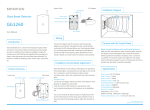
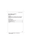
CG-105S
On-Site Alarm System
User Manual
2014 Chuango. All rights reserved.
Printed in China
PA: CG-105S-UM-EN-V1.0
Table of Contents
Foreword
Features
1
2
1~4
Product Overview
Working Mode
In the Box
On-Site Alarm Panel
Pet-Immune PIR Motion Detector
5~6
Test
Installation
Notices
Alarm Panel Overview
Power On
Connecting and Deleting Accessories
Power Off
23~25
Pairing the Remote Control
Testing and Installing Accessories
Remote Control
Product Overview
Arm(Away Arm)
Disarm
Home Mode (Stay)
Mute Operation
7~22
Pairing the Door/Window Contact
Pairing the Pet-Immune PIR Motion Detector
Deleting Accessories
Zone Setting For Wireless Accessories
Entry and Exit Delay
Act as an Accessories Kit
26~27
28
29~30
SOS
Nightlight On/Off
Door/Window Contact
Product Overview
Test
Installation
Pairing the Siren to the Control Panel
Pairing Other Wireless Detector to the Control Panel
Deleting the Siren from the Control Panel
Deleting Accessories from the Control Panel
Specifications
31~34
Foreword
Features
Dear Customers:
100% wireless configuration, easy to use
Thank you for purchasing CG-105S. This product is a totally plug &
Compact and streamline design
play wireless home security solution. It features automatic pairing to
One-button pairing
various accessories, putting your home under all-round protection.
Work as accessory or standalone alarm panel
To experience this wonderful product, please follow the instructions
Built-in battery for 8-hour standby
in the user manual. If there is any problem when using the product,
Mute operation
please contact us for help.
Support 40 wireless accessories (including remote control)
Built-in 1,000,000 RF codes combination maintains high reliability
Please read this manual carefully before using.
Please kindly keep this user manual for your reference when necessary.
1
2
In the Box
DWC-102 Wireless Door/Window Contact x 1
The door/window contact can be installed on doors,
WS-105 Alarm Panel x 1
The alarm panel receives and processes
windows and any other objects that open and close. The
sensor transmits signals to the control panel when a
magnet mounted near the sensor is moved away.
signals from wireless accessories. When the
accessory is triggered, the panel will alarm
and the strobe light will flash to deter
RC-80 Wireless Remote Control x 2
intruders. With plug-in design, it is powered
by AC 100~240V by plugging it into a wall
The remote control is compact and portable; it is
outlet.
convenient to carry it to arm, disarm, part arm the alarm
system and also make an emergency call.
PIR-910 Pet-Immnue PIR Motion Detector x 1
The wireless PIR Motion Detector is an intelligent
passive infrared motion sensor, designed to
detect human movements within an approximate
range of 0 to 8 meters from the detector. The
detector includes fuzzy logic to minimize false
alarms from unwanted heat sources. With power
Bracket for PIR Motion Detector x 1
Double-sided Tape for Door/
Window Contact x 2
User Manual x 1
Screws and Wall Plugs x 2
saving feature, the detector will enter sleeping
mode after the second activation within 3
minutes to save power. The detector features pet
immunity for small animals up to 25kgs.
3
4
On-Site Alarm Panel
Alarm Panel Overview
Power On
The siren is powered off by default. Plug the siren into a power outlet.
Press the power button. It beeps once, indicating power is on.
Power button/connect button
Strobe light
Siren and Strobe Light
5
Status
Siren
Strobe Light
Arm or Home Arm
Beeps once
Flashes once and then on
Power Off
Disarm
Beeps twice
Flashes twice and then off
Mute Arm
No beep
Lights on
press and hold the power button for 6 seconds until a beep is
Mute Disarm
No beep
Lights off
heard, indicating power is off.
After the siren is powered on, press the power button once. Then,
6
Testing and Installing Accessories
Disarm
Remote Control
Product Overview
LED Indicator
Arm
Stay
Disarm
Panic
Press the [Disarm
] button. The siren beeps twice, indicating the
system is disarmed.
Home Mode (Stay)
Arm (Away Arm)
] button, 3 seconds later, the siren beeps once,
Press the [Stay
indicating the system is in home mode.
Press the [Arm
] button. The siren beeps once, indicating
the system is armed.
When the whole system is in home mode, all the detectors in
normal zone are armed except those in home mode zone, while
the home mode detectors are in disarmed status, users can move
freely within the range of the disarmed area.
Note: Home mode requires the zone setting on detectors. For more details
please refer to page 26-27.
7
8
Mute Operation
Press and hold the [Stay
] button for 1 second, then press the
[Arm ] button within 3 seconds. The system is armed silently.
Nightlight On/Off
Press the [Stay
] button twice, the siren switches to home mode
silently and the nightlight is on.
Press and hold the [Stay
] button for 1 second, then press the
[Disarm ] button within 3 seconds. The system is disarmed
SOS
Press the [Disarm
off the nightlight.
] button twice, the siren disarms and switches
Press the [SOS] button on the remote control, the system will
alarm immediately.
9
10
Door/Window Contact
Product Overview
Test
LED Indicator
Transmitter
This is to test whether the contact can work properly.
1
Remove the insulating strip
Remove the insulating strip, the contact works immediately.
2
Pay attention to the direction
There are triangle marks on the side of the transmitter and magnet.
Make sure the triangle marks face each other and within the range
of 1 cm.
Magnet
LED Indication
Meaning
Status
Door/window contact is triggered
Blinks once
Blinks once every 3 seconds
Low power indication, please replace
battery immediately
PCB Layout
AA 1.5V LR6
Tamper Switch
11
Zone Setting
12
3
Test the contact
Press the [Arm ] button. The system switches to armed status.
Separate the transmitter and magnet within the space more than 2
cm. If an alarm is triggered at once, that means the sensor is
working properly.
Secure the Contact with Screws
1
Remove the rear cover
2
Press the rear cover and slide
down to remove the rear cover.
Choose a suitable install location
Choose a suitable location on
the door or window.
>2cm
3
Installation
Make sure the contact works properly before installing it. There are
triangle marks on the side of the transmitter and magnet. Make
sure the triangle marks close to each other and within the range of
1 cm. As long as the space between the transmitter and magnet is
over 2 cm and the LED on the transmitter is on.
Tighten the screws
Follow the [UP] sign. Put the
screws through the tiny holes.
Then, tighten screws.
4
Close the rear cover
Slide the transmitter down
until it secures. Then, align the
transmitter and magnet.
Secure the Contact with
Double-sided Tapes
Secure the transmitter and magnet
on desired locations with doublesided tapes.
13
Note: Make sure the transmitter and magnet works properly on the desired
locations. If a metal door is installed, place spacers under the transmitter
and magnet. Do not apply the contact to a rolling shutter. Purchase
dedicated contacts for rolling shutters when necessary.
14
PCB Layout
Pet-Immune PIR Motion Detector
LED ON / OFF
Product Overview
Infrared sensor
Tamper switch
1. Detection window
2. LED indicator
3. Snap joint
4. Test button
5. Bracket
2
1
Infrared sensor
Zone setting
Working Mode
Testing Mode
LED Indication
Meaning
LED Status
15
Blinks continuously
Self-testing
Blinks once
Intrusion is detected
Blinks twice
Testing mode is finished, enters power saving
mode
Blinks once per 3
seconds
Low battery. Please replace the batteries
immediately
After self-testing, press the test button, the detector switches to the
testing mode and detects once every 10 seconds. After 3 minutes,
the LED blinks twice, and the detector switches to the power saving
mode.
Hold the test button and load the
battery, then release the test button,
the detector stands in testing mode,
it keeps detecting once every 10
seconds. Exit this state by reloading
the battery without holding the test
button.
16
Power Saving Mode
Test
The product is featured with power saving mode. If the detector
detects human body movement twice within 3 minutes, it will switch
to sleeping state to save power. At this time, the LED will not blink
and would not trigger an alarm. After no movement within the next
3 minutes, the detector switches back to working status
automatically.
This is to test whether the PIR detector works properly.
Case 1:
Initial start and then guard.
1
Remove the insulating strip
Press the snap joint to open the
rear cover. Then, remove the
insulating strip.
2
Arm the system
Press the [Arm ] button on
the remote control. The
system is in arm state.
Case 2:
Press the test button and then guard.
3 minutes later
Sleep after detecting human
movement twice
No human movement
within 3 minutes
Switch from sleep to guard.
Note: when the detector is in the sleeping state, make sure there is no human body
movement within 3 minutes, otherwise the detector remains asleep.
In sleeping state, it is recommended that you leave the room after arming the system,
ensure no human body movement within 3 minutes, and then come back to the room,
the siren will sound immediately.
3
Trigger an alarm
Keep pressing the test button at the back until the siren sounds. It
indicates that the PIR motion detector has been paired to the siren.
Detection Scope
0m
2m
4m
6m
8m
2m
Top view
110°
0m
Side view
17
18
Installation
After making sure the detector works properly, do as follows:
1
3
Test the PIR motion detector
Press the test button. It switches to the testing mode that lasts for 3
minutes. Walk in the detection scope and observe the LED indicator.
When any human body movement is detected, the LED blinks once.
Choose a suitable installation location
For installation notices, please see page 21~22.
2m
Ground
4
Fix the detector
Adjust the angle
Adjust the bracket angle to achieve the best detection effect.
Fix the installation bracket on the wall with screws, and then fit the
groove at the back of the detector on the bracket.
Side view
Top view
Note! If pet-immune function is applied, please do not adjust the angle up or down,
but keep it parallel with the wall.
19
20
Notices
Pay attention to the following during installation:
Choose a proper location
It is recommended to mount it at the height of 2m from the ground.
The detector aims at preventing intrusion. Detecting human body
movement at the entry or exit is critical for security.
Avoid facing to glass doors or
windows
Strong light interferes with detection
sensitivity. In addition, complicated
situations outside the door or
window, such as traffic flow, stream
of people, also should be avoided.
Avoid facing to or positioning close
to heat/cold sources
ON
Mount the detector in a proper angle
The installation angle affects sensitivity directly. The sensitivity is
optimal when the walk direction is vertical to the infrared direction.
Choose the best location and angle according to the actual situation
and detection scope diagram.
Heat/cold sources, such as heat
extraction units, heaters, air
conditioner, microwave oven,
refrigerator, may cause false
triggering, should be avoided.
Avoid facing to swinging objects
Swinging objects may also trigger
false alarm. Besides, if there are
two detectors covering the same
scope, adjust the locations to
prevent cross-interference.
21
22
Pairing the Door/Window Contact
Connecting and Deleting Accessories
Accessories need to be paired to the siren so that the siren can
receive signals from them, and sound the alarm. Accessories in the
kit have been paired to the siren before delivery, and ready for use.
If the siren does not alarm when detectors are triggered, please pair
them again. Accessories purchased separately must be paired to the
siren before use.
Pairing the Remote Control
1
2
Press the connect button on the siren
Press the connect button on the siren, it beeps once, 3 seconds
later, it beeps once again and the strobe flashes, indicating the siren
is ready for pairing.
1
Press the connect button on the siren
Press the connect button on the siren, it beeps once, 3 seconds
later, it beeps once again and the strobe flashes, indicating the siren
is ready for pairing.
2
Separate the transmitter and magnet
Make sure the triangle marks close to each other and within the
range of 1cm, and then separate them with the space more than 2
cm. The siren beeps once indicates successful pairing.
>2cm
Press any button on the remote control
Press any button on the remote control, the siren beeps once,
indicating successful pairing.
Note: If the siren beeps twice, it indicates the door/window contact has been paired
before.
Note: If the siren beeps twice, it indicates the remote control has been paired before.
23
24
Pairing the PIR Motion Detector
1
2
Press the connect button on the siren
Press the connect button on the siren, it beeps once, 3 seconds
later, it beeps once again and the strobe flashes, indicating the siren
is ready for pairing.
Press the test button on the PIR motion
detector
Press the test button at the back of the
PIR motion detector. The siren beeps
once, indicating successful pairing.
Zone Setting For Wireless Accessories
You can set zones by changing the jumpers in detectors. After the
setting, detectors can work in corresponding modes. It must be
paired to the siren again.
Zones include normal zone, home mode zone, single delay zone
and 24-H zone.
The detailed operations are as follows:
Remove the rear cover of a door/window contact or PIR motion
detector. Set the jumpers accordingly. Pay attention to the order of
D0-D3.
Normal zone: In arm or home mode state, the siren will sound
immediately when the detectors set to normal zone is triggered.
Note: If the siren beeps twice, it indicates the PIR motion detector has been paired
before.
Deleting Accessories
Deleting accessories is to disconnect accessories from the siren.
After that, the siren cannot receive signals from accessories nor
trigger alarms.
Press and hold the connect button on the siren for 6 seconds, the
siren beeps once and the strobe flashes twice, indicating all the
accessories are deleted.
25
Home mode zone: In home mode state, the siren will not sound
when the detectors set to home mode zone is triggered.
Single delay zone: Alarms will be delayed according to the set
delay time. You can set one or more detectors to single delay zone.
Generally, it is applies to the door/window contact at the entrance.
For example, if you do not want carry the remote control, set the
door/window contact to single delay zone and set the delay time to
30 seconds. After you enter home, the system in the arm state will
alarm 30 seconds later. The siren beeps once every 5 seconds,
reminding you to disarm the system.
24-H zone: In any condition, the system will alarm immediately
once the 24-H zone detector is triggered.
26
How to set:
Open the rear cover of the detector, change the array of jumpers to
the corresponding position as below (Mind the direction of D0-D3):
Entry and Exit Delay
The detectors should be set in single delay zone before using this
function.
Exit Delay (Arm Delay)
The whole alarm system enters armed status after the delay time.
Normal Zone
Home Mode Zone
Single Delay Zone
Note: The default zone setting for PIR motion detector is home mode zone.
The default zone setting for door/window contact is normal zone.
Entry Delay (Alarm Delay)
When the detectors which have been set to single delay zone are
triggered, siren will alarm after the delay time. If the detectors that
set to normal zone or home mode zone are triggered, siren will
alarm immediately.
24-H Zone
Note: It is recommended to set smoke detector,
gas detector or outdoor beam sensors at 24-H
zone which offer full-day detection.
Press the connect button twice, delaying for 15 seconds.
Press the connect button for three times, delaying for 30 seconds.
Press the connect button for four times, disabling the function.
Note: Press the [Arm ] button on the remote control twice. The system
switches to armed status immediately.
About single delay zone, please refer to page 26.
27
28
Act as an Accessory Kit
Pairing Other Wireless Detectors to the Control Panel
If user purchased our alarm system before, CG-105S can act as an
accessory kit, working with the control panel after successful pairing.
After control panel enters its pairing status (please refer to its user
manual), trigger the wireless detector, the control panel beeps once
to indicate successfully pairing.
Pairing the Siren to the Control Panel
Press the Connect Button on the Siren
Press the connect button on the siren, it beeps once, 3 seconds
later, it beeps once again and the strobe flashes, indicating the siren
is ready for pairing.
Press the [Arm] or [SOS] Button on the Control Panel
Press the [Arm ] or [SOS] button on the control panel, the siren
beeps once, indicating successful pairing.
Deleting the Siren from the Control Panel
Press and hold the connect button on the siren for 6 seconds. The
siren beeps once and the strobe flashes twice. All accessories are
deleted.
Deleting Accessories from the Control Panel
Please refer to the manual of control panel.
Exit the Pairing Status
Press the connect button on the siren, it beeps once, exiting the
pairing status.
Test Whether the Siren has been paired
Press the [Arm ] button on the remote control. If the siren and
control panel both beep once, it indicates the pairing succeeds. If
not, please pair them again.
29
30
Specifications
31
On-Site Alarm Panel
Wireless Remote Control
Item No.: WS-105
Item No.: RC-80
Power Supply
AC 100~240V, 50/60Hz
Backup Battery
3.7V 600mAh lithium battery
Volume
90dB
Static Current
≤ 13mA
Alarm Current
≤ 100mA
Radio Frequency
315MHz or 433.92MHz (±75KHz)
Housing
PC+ABS plastic
Operating condition
Temperature -10°C~+55°C
Relative Humidity ≤ 80% (non-condensing)
Dimensions (L×W×H)
90 x 90 x 42.2mm (Not include the plug part)
Power Supply
DC 3V (CR2025 lithium battery x 1pc)
Transmitting Current
≤ 7mA
Transmitting Distance
≤ 80m (in open area)
Radio Frequency
315MHz or 433.92MHz (± 75KHz)
Housing Material
ABS plastic
Operating Condition
Temperature -10°C ~ +55°C
Relative Humidity ≤80% (non-condensing)
Dimensions (L x W x H)
58 x 31 x 9.5mm
32
33
Wireless Door/Window Contact
Pet-Immune PIR Motion Detector
Item No. : DWC- 102
Item No. : PIR-910
Power Supply
DC 1.5V (AA 1.5V LR6 Battery x 1pc)
Static Current
≤ 35uA
Alarm Current
≤ 40mA
Transmitting Distance
≤ 80m (in open area)
Radio Frequency
315MHz or 433.92MHz (±75KHz)
Housing Mat erial
ABS plastic
Ope rating Condition
Tempe rature -10°C ~ +55°C
Relative Humidity ≤80% (non-condensing)
Transmitter Dimen sions (L x W x H)
71 x 34 x 17.5mm
Mag net Dimen sions (L x W x H)
51 x 12 x 13.5mm
Power Supply
DC 3V (AA 1.5V LR6 Battery x 2 pcs)
Static Current
≤ 90uA
Alarm Current
≤ 9.5mA
Detection Scope
8m/110°
Transmitting Distance
≤ 80m (in open area)
Radio Frequency
315MHz or 433.92MHz (± 75KHz)
Housing Mat erial
ABS plastic
Ope rating Condition
Tempe rature -10°C ~ +55°C
Relative Humidity ≤80% (non-condensing)
Detector Dimen sions (L x W x H)
108 x 52 x 36.8 mm
Bracket Dimen sions (L x W x H)
52 x 30 x 26.5 mm
34
产品型号
WS-105
部件名称
说明书
设
林寿
材
80克书写纸
印刷尺寸
210X142mm
成品尺寸
105X142mm
工
骑马钉-40P
版
PA: CG-105S-UM-EN-V1.0
计
艺
注:
双色、双面印刷
料
本