1
Product Overview
LED Indication
The LED indicator can be turned on or off by setting jumpers.
See"PCB Layout" above.
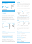
Curtain PIR Motion
Detector
PIR-800
1
User Manual
2
Flash continuously: Under self-testing state
Flash once: Intruder is detected
Flash twice: Testing mode is finished, enters power-saving
mode.
Flash once every 3 seconds: Undervoltage indication,
please change the batteries immediately.
3
Introduction
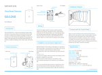
1. Detection Lens
2. LED Indicator
3. Test Button
4. Bracket
4
The detector works based on detecting human body’s infrared
spectrum. When human moves within the scope, the detector
receives the signal and inputs it into microprocessor after
magnification. Microprocessor continues to sample infrared
signal and send wireless signal to wireless control panel after
calculating, thus to form a security system. The product can be
applied in balcony, window, door and corridor etc.
PCB Layout
Zone Setting
LED ON/OFF
Testing mode: press test button, the sensor enters testing
mode and detects once every 10 seconds. After 3 minutes,
the LED flashes twice, the sensor enters the power saving
mode.
AAA LR03 1.5V
AAA LR03 1.5V
Accurate Detection
Digital dual-core fuzzy logic infrared control processing
technology
Effectively identify interference signals from body movement
signals through intelligent analysis
Compact Design
Small in size, not much space occupation
European-style design, adding artistic beauty to your home
Flexible Installation
Ceiling mounted or wall mounted for option
Energy-saving
Featured energy-saving mode enables 1 year standby
Remove the battery activation strip to activate batteries. It will
enter working state after one-minute's self-testing.
Mode Setting
Infrared Sensor
Features
Usage
Power-Saving Mode: In working state, if the sensor is
triggered twice within 3 minutes, it will enter sleeping mode
to save power. After no movement within next 3 minutes, the
sensor goes back to the working state.
Tamper Switch
Infrared sensor: Detecting human body’s infrared spectrum.
Don’t touch the surface by hand and keep it clean.
Tamper switch: Once the case is opened in working state, the
tamper switch will be triggered and then generates an alarm
signal.
Installation & Notice
Wall-mounting:
Fix the bracket longitudinally on the wall, and put the
detector on the bracket. Choose to mount it at the entry and
exit where intruder possibly breaks into. It is suggested to
mount it at the height of 2m from the ground.
Note: make sure the detection direction towards interior both
installed on wall and at ceiling. Adjust the bracket angle to optimize
the detecting effect.
Avoid mounting the detector close to air conditioner, electronic fan,
refrigerator, oven, heater and objects which will cause fast
temperature changing, and avoid mounting it in direct sunlight.
Avoid any objects blocking the lens, so as not to influence the
detection effect.
Specifications
Mount on wall
5m
0m
5m
0m
th
id
th 5
m
M
ax
e ng
.W
x. L
1.
3m
Max. Height 3.6m
Ma
Testing (Walk Test)
Mount at ceiling
th
id
th 5
m
M
ax
e ng
After installation, power on the detector. After self-testing for
1minute, press the test button, walk in the scope by crossing
the infrared spectrum (see below diagram), and watch the
LED indicator to make sure it is working. The LED indicator
will flash once when body movement is detected.
.W
x. L
1.
3m
Max. Height 3.6m
Ma
Max. Height 3.6m
High detection sensitivity
Power Supply:
DC 3V (AAA LR03 1.5V Battery x 2pcs)
Static Current:
≤ 50uA
Alarm Current:
≤ 9.5mA
Detection Distance:
5m
Curtain Detection Angle:
15°
Transmitting Distance:
≤ 80m (in open area)
Radio Frequency:
315MHz or 433.92MHz (±75KHz)
Housing Material:
ABS Plastic
Operation Condition
Temperature: -10°C ~+55°C
Relative Humidity: ≤ 80% (non-condensing)
Detector Dimensions (L x W x H):
48 x 33 x 88mm
Mounting Plate Dimensions (L x W x H):
52 x 30 x 11.6mm
1.
th
th 5
id
e ng
.W
x. L
m
ax
Ma
3m
Low detection sensitivity
M
Mount at door
When the control panel is in connecting state, press the test
button twice to send wireless signal. One beep is heard after
panel receives signal, which means successful connection.
Arm the system, trigger the detector again. The panel will
alarm immediately. This indicates the detector has
successfully connected with the panel.
Detection Range
Ceiling-mounting:
Fix the bracket laterally on the ceiling upper the door or
window, and put the detector on the bracket.
Connect with the Control Panel
Ver : PIR-800-UM-EN-V1.0
2014 Chuango. All rights reser ved.
产品型号
PIR-900
部件名称
说明书
设
林寿
材
料
80克书写纸
印刷尺寸
285X210mm
成品尺寸
95X70mm
工
折页
版
Ver: PIR-800-UM-EN-V1.0
计
艺
注:
双色、双面印刷
保持产品名称在最上面
本