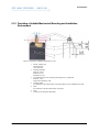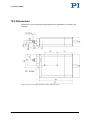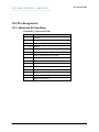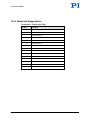
1
MP105E M-232 Linear Actuator User Manual Version: 1.1.0 Date: 22.10.2012 This document describes the following high-resolution linear actuators with limit switches: M-232.17 DC Drive, Travel Range 17 mm M-232.17S Stepper Motor Drive, Travel Range 17 mm Physik Instrumente (PI) GmbH & Co. KG · Auf der Römerstr. 1 76228 Karlsruhe, Germany Telephon +49 721 4846-0 · Telefax +49 721 4846-1019 · E-Mail [email protected] Physik Instrumente (PI) GmbH & Co. KG is the owner of the following trademarks: PI®, PIC®, PICMA®, PILine®, PIFOC®, PiezoWalk®, NEXACT®, NEXLINE®, NanoCube®, NanoAutomation®, Picoactuator®, PInano® © 2012 Physik Instrumente (PI) GmbH & Co. KG, Karlsruhe, Deutschland. The text, photographs and drawings in this manual are protected by copyright. With regard thereto, Physik Instrumente (PI) GmbH & Co. KG retains all the rights. Use of said text, photographs and drawings is permitted only in part and only upon citation of the source. Original instructions First printing: 22.10.2012 Document number: MP105E, MMa, Version 1.1.0 Subject to change without notice. This manual is superseded by any new release. The latest release is available for download on our website (http://www.pi.ws). Contents 1 About this Document 1.1 1.2 1.3 2 3 Goal and Target Audience of this Manual ............................................................1 Symbols and Typographic Conventions ...............................................................1 Other Applicable Documents ................................................................................2 Safety 2.1 2.2 3 Intended Use ........................................................................................................3 General Safety Instructions ..................................................................................3 2.2.1 Organizational Measures ....................................................................4 2.2.2 Safety Measures during Installation ...................................................4 2.2.3 Safety Measures during Start-Up .......................................................5 2.2.4 Safety Measures during Operation .....................................................6 2.2.5 Safety Measures during Maintenance ................................................6 Product Description 3.1 3.2 3.3 3.4 3.5 3.6 3.7 3.8 1 7 System Overview ..................................................................................................8 Features and Applications ....................................................................................9 Model Overview ..................................................................................................10 Product View.......................................................................................................11 Scope of Delivery ...............................................................................................11 Suitable Controllers ............................................................................................12 Accessories ........................................................................................................12 Technical Features .............................................................................................13 3.8.1 Rotary Encoder .................................................................................13 3.8.2 Limit Switches ...................................................................................13 4 Unpacking 15 5 Installation 17 5.1 5.2 5.3 General Notes on Installation .............................................................................17 Installing the Actuator in a Mechanical Mounting ...............................................18 5.2.1 Providing a Suitable Mechanical Mounting and Installation Environment......................................................................................19 5.2.2 Installing the Actuator in a Mechanical Mounting .............................21 Installing the Actuator in a Micropositioning Stage.............................................23 6 Start-Up 6.1 6.2 7 29 General Notes on Start-Up .................................................................................29 Starting Up the Actuator .....................................................................................31 6.2.1 M232 Entries in the Stage Database of PI ......................................33 6.2.2 Operating Parameters of the Model with DC Motor .........................34 6.2.3 Operating Parameters of the Model with Stepper Motor ..................35 Maintenance 7.1 7.2 7.3 37 General Notes on Maintenance ..........................................................................37 Lubricating the M232 .........................................................................................37 Cleaning the M232 ............................................................................................38 8 Troubleshooting 39 9 Customer Service 41 10 Technical Data 43 10.1 10.2 10.3 Specifications......................................................................................................43 10.1.1 Data Table ........................................................................................43 10.1.2 Ambient Conditions and Classifications ...........................................45 10.1.3 Limit Switch Specifications ...............................................................45 Dimensions .........................................................................................................46 Pin Assignment ...................................................................................................47 10.3.1 Model with DC Gear Motor ...............................................................47 10.3.2 Model with Stepper Motor .................................................................48 11 Old Equipment Disposal 49 12 EC Declaration of Conformity 51 1 About this Document 1 About this Document In this Chapter Goal and Target Audience of this Manual ..................................................................... 1 Symbols and Typographic Conventions ........................................................................ 1 Other Applicable Documents ......................................................................................... 2 1.1 Goal and Target Audience of this Manual This manual contains information on the intended use of the M232. It assumes that the reader has a fundamental understanding of basic servo systems as well as motion control concepts and applicable safety procedures. For updated releases of this user manual, or if you have any questions, contact our customer service department (p. 41). 1.2 Symbols and Typographic Conventions The following symbols and typographic conventions are used in this user manual: CAUTION Dangerous situation If not avoided, the dangerous situation will result in minor injury. Actions to take to avoid the situation. NOTICE Dangerous situation If not avoided, the dangerous situation will result in damage to the equipment. Actions to take to avoid the situation. M-232 Linear Actuator MP105E Version: 1.1.0 1 1 About this Document INFORMATION Information for easier handling, tricks, tips, etc. Symbol Meaning 1. Action consisting of several steps whose sequential order must be observed 2. Action consisting of one or several steps whose sequential order is irrelevant List item p. 5 Cross-reference to page 5 RS-232 Labeling of an operating element on the product (example: socket of the RS-232 interface) 1.3 Other Applicable Documents The devices and software tools which are mentioned in this documentation are described in their own manuals. For the latest versions of the user manuals contact our customer service department (p. 41). 2 Controller Document C-843 DC-Motor Controller PCI PC Board MS77E User Manual C-863.10 DC-Motor Controller MS173E User Manual C-863.11 DC-Motor Controller MS205E User Manual C-663.10 Stepper Motor Controller MS138E User Manual C-663.11 Stepper Motor Controller MS208E User Manual Version: 1.1.0 MP105E M-232 Linear Actuator 2 Safety 2 Safety In this Chapter Intended Use ................................................................................................................. 3 General Safety Instructions ........................................................................................... 3 2.1 Intended Use The M232 is a laboratory device as defined by DIN EN 61010-1. It is intended to be used in interior spaces and in an environment which is free of dirt, oil, and lubricants. Based on its design and realization, the M232 is intended for positioning, adjusting and shifting loads in one axis at various velocities. The intended use of the M232 is only possible when installed and with a suitable controller (p. 12). The controller is not included in the scope of delivery of the M232. 2.2 General Safety Instructions The M232 is built according to state-of-the-art technology and recognized safety standards. Improper use can result in personal injury and/or damage to the M232. Only use the M232 for its intended purpose, and only use it if it is in a good working order. Read the user manual. Immediately eliminate any faults and malfunctions that are likely to affect safety. The operator is responsible for the correct installation and operation of the M232. M-232 Linear Actuator MP105E Version: 1.1.0 3 2 Safety 2.2.1 Organizational Measures User manual Always keep this user manual next to the M232. If the user manual is lost or damaged, contact our customer service department (p. 41). Add all information given by the manufacturer to the user manual, for example supplements or Technical Notes. If you pass the M232 on to other users, also turn over this user manual as well as all other relevant information provided by the manufacturer. Only use the device on the basis of the complete user manual. Missing information due to an incomplete user manual can lead to slight injury as well as property damage. Only install and operate the M232 after having read and understood this user manual. Personnel qualification The M232 may only be started up, operated, maintained and cleaned by authorized and qualified staff. 2.2.2 Safety Measures during Installation A cable break leads to a failure of the linear actuator. Install the linear actuator so that the cable is not bent or squeezed too severely during operation. Lateral forces that affect the pusher of the linear actuator increase the friction on the internal drive components. Increased friction impairs the motion of the pusher and increases wear on the drive components. Avoid lateral forces on the pusher of the M232. Overtightening the mounting screws can damage the mounting shaft of the linear actuator and hinder the motion of the pusher. This reduces the positioning accuracy. Tighten the mounting screws to a maximum torque of 0.3 Nm. 4 Version: 1.1.0 MP105E M-232 Linear Actuator 2 Safety The heat produced during operation of the M232 can affect your application. Install the M232 so that your application is not affected by the dissipating heat. 2.2.3 Safety Measures during Start-Up A motorized linear actuator can generate powerful forces depending on the gear ratio. Connecting a linear actuator to an unsuitable controller can cause damage to the linear actuator or controller. Connect a linear actuator with DC motor to a DC motor controller only. Connect a linear actuator with stepper motor to a stepper motor controller only. Faulty motor controllers can cause unintentional motor motion and run the M232 into the hard stop. The linear actuator can perform an unintentional motion when connecting it to the motor controller. Do not place any objects in areas where they can get caught by moving parts. Keep your fingers at a safe distance from the motion range of the M232. The collision of moving parts with the hard stop (end of travel range), as well as high acceleration, can cause damage to, or considerable wear on the mechanical system. In the event of a malfunction of the motor controller, stop the motion immediately. Ensure that theend of the travel range is approached at low velocity. Set your control signal so that the moving part does not stop abruptly or try to continue moving at the end of the travel range. Determine the maximum velocity for your application. M-232 Linear Actuator MP105E Version: 1.1.0 5 2 Safety Ensure that the automatic limit switch halt is supported by the controller, or that it is activated in the controller. 2.2.4 Safety Measures during Operation For models with DC motors: Unsuitable settings made to the servo-control parameters can impair the performance of the M232. The consequences of this can be expressed as follows: Oscillations Imprecise approach of the position Settling time is too long If the performance of the M232 is not satisfactory, check the settings for the servo-control parameters of your controller. 2.2.5 Safety Measures during Maintenance The M232 is precisely aligned. Do not loosen any sealed screw. 6 Version: 1.1.0 MP105E M-232 Linear Actuator 3 Product Description 3 Product Description In this Chapter System Overview ........................................................................................................... 8 Features and Applications ............................................................................................. 9 Model Overview ........................................................................................................... 10 Product View ............................................................................................................... 11 Scope of Delivery ........................................................................................................ 11 Suitable Controllers ..................................................................................................... 12 Accessories ................................................................................................................. 12 Technical Features ...................................................................................................... 13 M-232 Linear Actuator MP105E Version: 1.1.0 7 3 Product Description 3.1 System Overview The following figure shows an overview of the total system. Figure 1: Overall system, overview To operate the actuator in your application, the following components are necessary: Component Task Supplied by or available from PI Peripheral control equipment Loads configurations and control commands to the controller (e.g. PC in connection with PC software). PC software (e.g. PIMikroMove) included in the scope of delivery of PI controllers. Controller Controls the motions of the actuator. Stand-alone device or motor controller card (PC add-on card). Available separately, see section "Suitable Controllers" (p. 12). Actuator Produces the motions of the part to be driven or the load in your application. Here: linear actuator, type M232. Present product. 8 Version: 1.1.0 MP105E M-232 Linear Actuator 3 Product Description Component Task Supplied by or available from PI Cables Peripheral control equipment to controller: Ensures the data communication. Transmission cable between PC and controller. Included in the scope of delivery of PI controllers. Controller to actuator: Ensures the data communication and the power source of the actuator. Transmission cable between controller and actuator: Part of the actuator or included in the scope of delivery of the piezo actuator. Mechanical structure Ensures among other things the secure fixation of the actuator and thus a high repeatability. Only mounting nut (for mechanical connection) included in the scope of delivery of the actuator. Mechanical coupling Establishes the connection between the actuator and the load (pusher with a separate end piece, depending on the model). Also in case exchangeable parts can be used, all options are included in the scope of delivery of the actuator (e.g. end pieces). Load Part to be driven. This is to be moved in your application. - If a motor controller card is used, the "controller" component and the connection between the peripheral control equipment and the controller ("cable") are physically inside of the PC. 3.2 Features and Applications The M232 is a compact and cost-effective linear actuator with a 17 mm travel range and a length that could be reduced with a folded drive to only 72 mm. As a result of the combination of a backlash-free preloaded DC gear motor with high-resolution rotary encoder and an extremely low-friction and zero-backlash design, the M232 achieves minimum incremental motions of 100 nm and velocities of up to 2.5 mm/s. A design with a stepper motor is also on offer. Integrated limit switches as well as line drivers enable easy installation in automation solutions and protect the mechanical system of the actuator. The M232 can be installed, for example, on the fiber positioning system / micropositioning stage M-105 or M-106 instead of a micrometer screw or a piezo drive. M-232 Linear Actuator MP105E Version: 1.1.0 9 3 Product Description 3.3 Model Overview Two versions of the M232 are available. They differ in terms of their drive type. Model Name M-232.17 Compact High-Resolution DC Mike Linear Actuator, 17 mm, Limit Switches M-232.17S Compact High-Resolution Stepper Mike Linear Actuator, 17 mm, Limit Switches For further technical data, see the specifications (p. 43). PI also produces custom designs upon request. Custom designs can differ from the described standard products in respect to dimensions, characteristics or other technical data. If necessary, contact our customer service department (p. 41) directly. 10 Version: 1.1.0 MP105E M-232 Linear Actuator 3 Product Description 3.4 Product View Figure 2: Product view 1 Moving pusher, rotating, with M3.5 thread and convex end 2 Mounting shaft with circumferential groove 3 Locating surface 4 Continuous mounting hole, M3 thread 5 Case 6 Cable for connecting to the controller 3.5 Scope of Delivery Order Number Items M232 Linear actuator according to order (p. 10) C-815.38 Motor cable, 3 m, Sub-D, 15-pin (m/f) MP105E User manual (this document) in printed form M-232 Linear Actuator MP105E Version: 1.1.0 11 3 Product Description 3.6 Suitable Controllers The M232 must be connected to a suitable controller. The following controllers from PI are suitable for the operation of the M232: Drive Type Controller Axes per Controller PCInterface Multiple Controllers on the Same PC DC motor C-843 2 or 4 Internal (PCI bus) Yes, separate boards C-863 1 USB, RS-232, daisy chain Yes, same interface C-663 1 USB, RS-232, daisy chain Yes, same interface Stepper motor The required PC software is included in the scope of delivery of the PI controllers. The operation of the controllers is described in the corresponding user manuals. The operating parameters must be adjusted depending on the version of the M232 used (p. 31). 3.7 Accessories Order Number Description C-842.AP1 PWM-to-analog adapter box for operating M232 linear actuators with PWM signals C-815.83 Motor cable 10 m, Sub-D, 15-pin (m/f) To order, contact our customer service department (p. 41). 12 Version: 1.1.0 MP105E M-232 Linear Actuator 3 Product Description 3.8 Technical Features 3.8.1 Rotary Encoder The models with DC motors are equipped with a rotary encoder. A rotary encoder, also called an incremental or incremental rotary encoder, is implemented at a rotating point in the drivetrain, e.g. the motor shaft. To determine the relative position, the controller counts the encoder signals, the so-called impulses. 3.8.2 Limit Switches The M232 is equipped with non-contact, Hall-effect limit switches. Each limit switch sends an overtravel signal on a dedicated line to the controller. The controller then stops the motion. If the controller does not stop the motion in time, the linear actuator runs into the hard stop. See "Limit Switch Specifications" (p. 45) for more information. M-232 Linear Actuator MP105E Version: 1.1.0 13 4 Unpacking 4 Unpacking 1. Unpack the M232 with care. 2. Compare the contents against the items covered by the contract and against the packing list. 3. Inspect the contents for signs of damage. If parts are missing or you notice signs of damage, contact PI immediately. 4. Keep all packaging materials in case the product needs to be returned. M-232 Linear Actuator MP105E Version: 1.1.0 15 5 Installation 5 Installation In this Chapter General Notes on Installation ...................................................................................... 17 Installing the Actuator in a Mechanical Mounting ........................................................ 18 Installing the Actuator in a Micropositioning Stage ..................................................... 23 5.1 General Notes on Installation NOTICE Cable break! A cable break leads to a failure of the linear actuator. Install the linear actuator so that the cable is not bent or squeezed too severely during operation. NOTICE Increased friction! Lateral forces that affect the pusher of the linear actuator increase the friction on the internal drive components. Increased friction impairs the motion of the pusher and increases wear on the drive components. Avoid lateral forces on the pusher of the M232. NOTICE Heating up of the M-232 during operation! The heat produced during operation of the M232 can affect your application. Install the M232 so that your application is not affected by the dissipating heat. INFORMATION Linear actuators with DC gear motors are equipped with integrated signal drivers for cable lengths of ≤10 m between linear actuator and motor controller. M-232 Linear Actuator MP105E Version: 1.1.0 17 5 Installation INFORMATION The M232 is suitable for installation in the following fixtures: Suitable mechanical mounting PI micropositioning stages / fiber positioning systems of the types M-105 and M106 The necessary steps are described in the following sections. INFORMATION To achieve an optimum repeatability, the mounting shaft must not have any backlash. During mounting, make sure that there is a faultless connection between the actuator and the mechanical mounting. 5.2 Installing the Actuator in a Mechanical Mounting To install the actuator in a mechanical mounting, the following steps are required: 1. Providing a suitable mechanical mounting 2. Installing the actuator in the mechanical mounting Detailed instructions can be found in the following sections. 18 Version: 1.1.0 MP105E M-232 Linear Actuator 5 Installation 5.2.1 Providing a Suitable Mechanical Mounting and Installation Environment Figure 3: Components, installation dimensions (in mm) M-232 Linear Actuator 1 Pusher, rotating, with M3.5 thread and R3 convex end 2 Mounting shaft with width (a): 2.5 mm width (c) 3.5 mm diameter (e): 6 mm 3 Circumferential groove for mounting a mounting screw, V profile with width (b): 1 mm angle to the vertical axis: ±45° 4 Locating surface For dimensions, see sectional view on the right (relevant e.g. for installation in M-105) 5 Slant For dimensions, see the sectional view on the right 6 Case 7 Continuous mounting hole, M3 thread MP105E Version: 1.1.0 19 5 Installation Figure 4: Example for the installation of a linear actuator (here: an M-235) A suitable mechanical mounting and installation environment are necessary for the proper use of the actuator. Make sure that the following conditions have been met: − Material and statics of the mounting are designed so that the static and dynamic forces that occur can be safely and continuously managed. − The dimensions of the mounting have been adjusted to the dimensions of the actuator (see above figures and dimensions (p. 46)), especially to the following specifications: - Diameter of the mounting shaft - Slant and locating surface if a positive connection is planned - Position of the circumferential groove if a fixation with engaging mounting screws is planned − The intended motions of the pusher and the load must not be inhibited by the dimensions of the installation environment. Take into account the following specifications when planning the application and installing the actuator: 20 − Travel range: max. 17 mm − Space requirements for a kink-free and proper guiding of the connection cable and motor cable if necessary − Length of the connection cable (approx. 0.5 m) and additional motor cables (3 m or 10 m) Version: 1.1.0 MP105E M-232 Linear Actuator 5 Installation Avoid or label danger areas that result from the installation of the actuator and from use, in accordance with the legal regulations (e.g. risk of crushing in the case of heavy moving loads, fast actuator motions and/or high drive torques). Check whether the limit switches (for a pusher displacement of 0 mm or 17 mm) can be reached with the planned design of your application. If the limit switches of the actuator cannot be reached with the planned minimum and maximum displacements: Make sure that the actuator and the load only move within the planned range. Suitable measures: − Corresponding programming of the controller − Emergency off switch − Automatic shutdown systems The complete dimensions of the actuator and relevant individual parts can be found in the figures in the section Dimensions (p. 46). 5.2.2 Installing the Actuator in a Mechanical Mounting NOTICE Overtightened mounting screws! Overtightening the mounting screws can damage the mounting shaft of the linear actuator and hinder the motion of the pusher. This reduces the positioning accuracy. Tighten the mounting screws to a maximum torque of 0.3 Nm. INFORMATION Two continuous mounting holes with M3 thread are present in the case of the linear actuator, see the figures in "Product View (p. 11)" or "Providing a Suitable Mechanical Mounting and Installation Environment (p. 18)". These holes can be used alternatively or in addition to the procedure shown here for installing the actuator. See the dimensional drawing (p. 46) for the position of the continuous mounting holes. M-232 Linear Actuator MP105E Version: 1.1.0 21 5 Installation Figure 5: Example for the installation in a mechanical mounting, sectional view 1 Mechanical Mounting 2 Mounting screw (e.g. M2 grub screw) 3 Mounting shaft with circumferential groove 4 Sleeve / case of the actuator We recommend fixing the actuator with at least one mounting screw, which is screwed into each mechanical mounting and engages in the groove of the mounting shaft. The following instructions apply to this case. If you use other designs, proceed correspondingly. Prerequisites 22 You have read and understood the General Notes on Installation (p. 17). You have provided your application with a suitable mounting for the mounting shaft of the linear actuator in accordance with the instructions of the previous section. Version: 1.1.0 MP105E M-232 Linear Actuator 5 Installation You have made a suitable hole with internal thread in the mechanical mounting for each of the planned mounting screws. The hole is positioned so that the mounting screw can engage vertically in the circumferential groove of the mounting shaft after installation. The position of the circumferential groove can be found in the above illustration of the components and installation dimensions. Tools and accessories At least one suitable mounting screw, e.g. M2 grub screw. To be able to engage in the groove optimally, the screw should have an angled end instead of a flat end. Suitable Allen wrench or screwdriver for the mounting screw(s). Installing the actuator in a mechanical mounting 1. Insert the actuator in the mounting of your application. 2. Place the groove of the mounting shaft precisely across the holes for mounting screws. 3. Screw all mounting screws into the threaded hole of the mounting with a maximum torque of 0.3 Nm each time until you feel resistance. 4. Check that the actuator is correctly fitted in the mounting. 5.3 Installing the Actuator in a Micropositioning Stage The M232 is suitable, e.g., for installation in a PI micropositioning stage / -fiber positioning system of the type M-105 or M-106. NOTICE Overtightened mounting screws! Overtightening the mounting screws can damage the mounting shaft of the linear actuator and hinder the motion of the pusher. This reduces the positioning accuracy. Tighten the mounting screws to a maximum torque of 0.3 Nm. Prerequisites You have read and understood the General Notes on Installation (p. 17). If necessary: you have disassembled the drive of the micropositioning stage (e.g. micrometer screw or piezo drive). M-232 Linear Actuator MP105E Version: 1.1.0 23 5 Installation Tools and accessories AF 1.5 Allen wrench for M2 grub screw or corresponding screwdriver Micropositioning stage with suitable mounting for the linear actuator. Installing the actuator in a micropositioning stage Figure 6: Actuator and stage, schematic 1 Moving platform (internal) 2 (Wide) micropositioning stage front with (a) horizontal hole (b) vertical threaded hole with grub screw 3 Pusher 4 Mounting shaft with (c) groove 5 Locating surface 6 Sleeve / case 1. If possible, place the micropositioning stage on a level surface. The moving platform must be visible from above. 24 Version: 1.1.0 MP105E M-232 Linear Actuator 5 Installation 2. Unscrew the grub screw in the middle of the front of the micropositioning stage by around three rotations using an Allen wrench or screwdriver. Figure 7: Unscrew the grub screw slightly 3. Align the actuator so that the following conditions are met: − The locating face of the actuator is level with the top edge of the micropositioning stage. − The mounting shaft is located precisely across from the horizontal hole on the front of the micropositioning stage. Figure 8: Aligning the actuator M-232 Linear Actuator MP105E Version: 1.1.0 25 5 Installation 4. Insert the mounting shaft of the actuator into the horizontal hole on the front of the micropositioning stage until the locating surface of the actuator and the front of the micropositioning stage touch. The grub screw is then precisely above the circumferential groove of the mounting shaft. Figure 9: Introducing the shaft 5. Screw in the grub screw until you feel resistance. The torque must not exceed 0.3 Nm. Fine adjustment: If necessary, correct the position of the locating surface of the actuator in relation to the top edge of the micropositioning stage while or before tightening the grub screw so that they are flush with each other. Figure 10: Fastening the actuator 6. Check that the actuator is correctly fitted on the micropositioning stage: − 26 Make sure that the installation result corresponds to the conditions in the following figure. Version: 1.1.0 MP105E M-232 Linear Actuator 5 Installation Figure 11: Complete installation: M-232 actuator in a micropositioning stage (here: M-105) 1 M-232 Linear Actuator Moving platform of the micropositioning stage 2 Pusher of the M-232 actuator, here completely extended 3 Mounting screw: M2 grub screw 4 Locating surface of the M-232 actuator, flush with the top edge of the front of the micropositioning stage MP105E Version: 1.1.0 27 6 Start-Up 6 Start-Up In this Chapter General Notes on Start-Up .......................................................................................... 29 Starting Up the Actuator .............................................................................................. 31 6.1 General Notes on Start-Up CAUTION Unintentional motion of the linear actuator while connecting it to the motor controller! Do not place any objects in areas where they can get caught by moving parts. Keep your fingers at a safe distance from the motion range of the linear actuator. NOTICE Damage if a wrong motor controller is connected! Connecting a linear actuator to an unsuitable controller can cause damage to the linear actuator or controller. Connect a linear actuator with DC motor to a DC motor controller only. Connect a linear actuator with stepper motor to a stepper motor controller only. NOTICE Damage due to the pusher crashing into the hard stop! When the limit switches are deactivated, the motion of the pusher is aborted by the hard stop and the M232 can be damaged. Do not deactivate the limit switches in the software. Test limit switch operation at low velocities only. M-232 Linear Actuator MP105E Version: 1.1.0 29 6 Start-Up NOTICE Damage or major wear to the mechanical system as a result of high acceleration! In the event of a malfunction of the motor controller, stop the motion immediately. Ensure that the end of the travel range is approached at low velocity. Set your control signal so that the moving part does not stop abruptly or try to continue moving at the end of the travel range. Determine the maximum velocity for your application. NOTICE Damage from unsuitable controllers and PC software! Unsuitable controllers and PC software can cause damage to the actuator. If you use controllers and software from other manufacturers, before starting up the actuator, check the technical data to make sure that they are suitable! INFORMATION The maximum velocity for a linear actuator with a stepper motor should be determined in the application. If the commanded velocity is too high, the stepper motor might stop without the controller detecting this condition. INFORMATION The handwheel of a linear actuator with stepper motor can be used to manually retract and extend the pusher. Manually triggered changes in the position of the pusher are not recognized by the connected controller. INFORMATION The repeatability of the positioning is only ensured when the same limit switch is always used for the reference move. 30 Always start reference moves to the same limit switch. Version: 1.1.0 MP105E M-232 Linear Actuator 6 Start-Up INFORMATION For models with DC motors: Unsuitable settings made to the servo-control parameters can impair the performance of the M232. The consequences of this can be expressed as follows: Oscillations If the performance of the M232 is not satisfactory, check the settings for the servo-control parameters of your controller. Imprecise approach of the position Settling time is too long INFORMATION Moving the pusher outwards corresponds to the positive direction of motion. 6.2 Starting Up the Actuator In the following, a PC with PC software is used as the peripheral control equipment of the controller. Prerequisites You have read and understood the General Notes on Start-Up (p. 29). You have correctly installed the actuator (p. 17). You have read and understood the user manual of the used controller. You have read and understood the manual of the used PC software. Accessories Suitable controller (p. 12) - motor controller card for PC installation or standalone device incl. connection cable to PC. PC If necessary, suitable motor cable from PI, e.g.: PC software for the controller (for PI controllers: included in their scope of delivery) − M-232 Linear Actuator Motor cable C-815.38, 3 m, Sub-D, 15-pin (m/f), in the scope of delivery (p. 11). MP105E Version: 1.1.0 31 6 Start-Up − Motor cable C-815.83, 10 m, Sub-D, 15-pin (m/f), available as optional accessory (p. 11). Starting up the actuator 1. If you use a motor controller card (e.g. C-843 from PI), make sure that it is properly installed or install it (see the user manual of the motor controller card). 2. If suitable and current PC software for the controller is not on your PC yet, install the PC software (see the user manual of the controller or the software). 3. If you do not use a motor controller card, connect the PC with the external controller using a suitable cable. For PI products: the cable required for this is included in the scope of delivery. 4. Connect the actuator with the controller: a) b) c) d) Determine the minimum necessary cable length between the actuator and the controller. Connect the connector of the connection cable with the Sub-D socket of the controller or a corresponding adapter (according to the determined length, see above) either directly or by interposing an additional motor cable. Secure all connections with the integrated screws against accidental disconnection. Remove or label resulting danger areas in accordance with the valid legal regulations and directives. 5. Start up the controller (see user manual of the controller). 6. Configure the controller using the PC software for the used actuator (see the user manual of the controller and the PC software): − If you use a PI controller: select the entry in the stage database that precisely matches the actuator version used, see the list of available entries (p. 33). − If you use a controller from another manufacturer: Enter the parameters in the corresponding PC software that precisely match the actuator version used; see overview of the operating parameters for DC motor controllers (p. 34) or stepper motor controllers (p. 35). 7. Start a few motion cycles for testing purposes (see user manual of the controller). 32 Version: 1.1.0 MP105E M-232 Linear Actuator 6 Start-Up 6.2.1 M-232 Entries in the Stage Database of PI For motor controllers from PI you can select the connected linear actuator from a stage database in the respective PC software. The appropriate operating parameters are thus loaded into the motor controller. You can find a detailed description in the user manual for the motor controller or in the manual for the PC software used. The following table shows the linear actuators and their names in the stage database. M-232 Name in the Stage Database Specifications in the Stage Database (Selection) M232.17 Motor type: DC motor; conservative set of servo-control parameters (adjustable initial values); limit switches active high M232.17-PWM Like the M232.17 except for parameters for PWM output, for use with C-842.AP1 PWM-toanalog adapter box M232.17 M232.17S M232.17S M-232 Linear Actuator Motor type: stepper motor; parameters for operating current, holding current and holding current delay; limit switches active low MP105E Version: 1.1.0 33 6 Start-Up 6.2.2 Operating Parameters of the Model with DC Motor If you use a DC motor controller from a third-party supplier, it may be necessary to enter operating parameters to adjust the used linear actuator. Parameter M-232.17 Unit P-term 250 - I-term 25 - D-term 250 - I-limit 2000 - Maximum acceleration 582542 counts/s² Maximum velocity 1.5 mm/s Maximum velocity 218453 counts/s Gear reduction 28.44444:1 - Encoder resolution 2048 counts/rev. Limit switch polarity Active high - Recommended start values: Hardware properties: 34 Version: 1.1.0 MP105E M-232 Linear Actuator 6 Start-Up 6.2.3 Operating Parameters of the Model with Stepper Motor If you use a stepper motor controller from a third-party supplier, it may be necessary to enter operating parameters to adjust the used linear actuator. Parameter M-232.17S Unit Holding current 100 mA Operating current 250 mA Holding current delay 1000 ms Maximum motor current 250 mA Maximum acceleration 121316 steps/s Maximum velocity 1 mm/s Maximum velocity 1706 steps/s Recommended start values: 2 Hardware properties: Gear reduction 28.44444:1 Limit switch polarity Active low - Full steps 24 steps/revolution Phase resistance 12.5 ohm Maximum phase current, bipolar 250 mA M-232 Linear Actuator MP105E Version: 1.1.0 35 7 Maintenance 7 Maintenance In this Chapter General Notes on Maintenance ................................................................................... 37 Lubricating the M232 .................................................................................................. 37 Cleaning the M232 ..................................................................................................... 38 7.1 General Notes on Maintenance NOTICE Damage due to improper maintenance! The M232 can become misaligned as a result of improper maintenance. Do not loosen any sealed screws. 7.2 Lubricating the M-232 Depending on the operational conditions and the period of use of the linear actuator, the following maintenance measures are required. Spreading lubricant If you operate the M232 continuously on a small travel range (<20% of the entire travel range), perform a maintenance run every 2000 motion cycles across the entire travel range. Lubrication Under laboratory conditions, the linear actuator needs extra lubrication in exceptional cases only. For continuous industrial use the lubrication intervals must be defined individually. Do not lubricate the M232 without consulting our customer service department (p. 41). To lubricate, follow the instructions given in the maintenance manual which you can obtain from our customer service department. M-232 Linear Actuator MP105E Version: 1.1.0 37 7 Maintenance 7.3 Cleaning the M-232 Prerequisites You have disconnected the linear actuator from the controller. Cleaning the linear actuator When necessary, clean the linear actuator surface with a towel lightly dampened with a mild cleanser or disinfectant. Do not use any organic solvents. 38 Version: 1.1.0 MP105E M-232 Linear Actuator 8 Troubleshooting 8 Troubleshooting Problem Possible Causes Solution Reduced positioning accuracy Mounting screw not tight enough or overtightened Functional impairment after system modification Motor controller has been replaced Motor controller from PI: Tighten the mounting screw with a maximum torque of 0.3 Nm. Load the parameters from the stage database that correspond to the combination of motor controller and M232 model (p. 31). Motor controller from a third-party supplier: The mechanical system does not move The cable is not connected correctly or is faulty Check the operating parameters Check the connector cable. Lateral forces are affecting Lateral forces increase the friction on the the pusher. internal drive components. Avoid lateral forces on the pusher of the M231. Reduce the velocity. The mechanical system does not move, but generates operating noise Values for the velocity, acceleration and/or load are too high Reduce the acceleration. Reduce the load on the mechanical system. The mechanical system did not stop in time and ran into the hard stop 1. Stop the motor. Velocity is too high (see chapter Limit Switches p. 13) 2. Command the mechanical system away from the hard stop. Limit switch is defective 3. Check the settings of the motor controller for the limit switch processing. Motor controller ignores the limit switch signal If the problem that occurred with your system is not listed in the table above or it cannot be solved as described, contact our customer service department (p. 41). M-232 Linear Actuator MP105E Version: 1.1.0 39 9 Customer Service 9 Customer Service For inquiries and orders, contact your PI sales engineer or send us an e-mail (mailto:[email protected]). If you have questions concerning your system, have the following information ready: Product codes and serial numbers of all products in the system Firmware version of the controller (if present) Version of the driver or the software (if present) Operating system on the PC (if present) The latest versions of the relevant user manuals for your system are available for download on our website (http://www.pi.ws). M-232 Linear Actuator MP105E Version: 1.1.0 41 10 Technical Data 10 Technical Data In this Chapter Specifications .............................................................................................................. 43 Dimensions .................................................................................................................. 46 Pin Assignment ............................................................................................................ 47 10.1 Specifications 10.1.1 Data Table M-232.17 M-232.17S Unit Tolerance High resolution, closed-loop High resolution, with stepper motor Travel range 17 17 Integrated sensor Rotary encoder – Sensor resolution 2048 – cts./rev. Design resolution 0.007 0.037 µm typ. Min. incremental motion 0.1 0.1 µm typ. Backlash 2 2 µm typ. Unidirectional repeatability 0.2 0.2 µm typ. Velocity 1.5 1 mm/s max. Drive screw Leadscrew Leadscrew Thread pitch 0.4 0.4 Gear ratio 28.44444:1 28.44444:1 Motor resolution – 384* steps/rev. Push / pull force 40 40 N Motion and positioning mm Mechanical properties M-232 Linear Actuator MP105E mm Version: 1.1.0 max. 43 10 Technical Data M-232.17 M-232.17S Unit Tolerance Drive properties Motor type DC motor, gearhead 2-phase stepper motor* Operating voltage 0 to ±12 24 V Electrical power 2 – W Limit switches Hall-effect Hall-effect Operating temperature range -20 to 65 -20 to 65 Material Aluminum anodized, Aluminum chrome steel anodized, chrome steel Mass 0.17 0.17 Cable length 0.5 + 3 m extension cable (included) 0.5 + 3 m extension m cable (included) Connector 15-pin sub-D, incl. encoder driver Sub-D, 15-pin Miscellaneous Recommended controller/driver C-863 single-axis °C kg ±5 % ±10 mm C-663 single-axis C-843 PCI board, for up to 4 axes Avoid lateral forces on the pusher! Ask about custom designs! * Max. 0.25 A/phase; 24 full steps/rev., motor resolution with C-663 stepper motor controller. 44 Version: 1.1.0 MP105E M-232 Linear Actuator 10 Technical Data 10.1.2 Ambient Conditions and Classifications The following ambient conditions and classifications must be observed for the M232: Area of application For indoor use only Maximum altitude 2000 m Relative humidity Highest relative humidity 80% for temperatures up to 31°C Decreasing linearly to 50% relative humidity at 40°C Storage temperature 0°C to 80°C Transport temperature 0°C to 80°C Supply fluctuations Not more than ±10% of the nominal voltage Degree of pollution 2 Degree of protection according to IEC 60529 IP40 10.1.3 Limit Switch Specifications Type Magnetic (Hall-effect) sensor Supply voltage +5 V/ground Signal output TTL level Signal logic The signal level changes when passing the limit switch. The signal logic depends on the model type: Models with DC motor: active high. That means: − Normal motor operation: low (0 V) − Limit switch reached: high (+5 V) Models with stepper motor: active low. That means: − − M-232 Linear Actuator Normal motor operation: high (+5 V) Limit switch reached: low (0 V) MP105E Version: 1.1.0 45 10 Technical Data 10.2 Dimensions Dimensions in mm. Note that the decimal places are separated by a comma in the drawings. Figure 12: M-232.17 and M-232.17S linear actuator, dimensions in mm 46 Version: 1.1.0 MP105E M-232 Linear Actuator 10 Technical Data 10.3 Pin Assignment 10.3.1 Model with DC Gear Motor Connector: 15-pin sub-D (m) Pin No. Function 1 Internal 9 2 Input: Motor (-) Input: Motor (+) 10 3 Internal Internal 11 4 Internal Input: +5 V supply from controller 12 5 Output: Limit switch signal, negative side Output: Limit switch signal, positive side 13 6 Internal GND (limit switch and logic) 14 7 Output: Encoder A (+) Output: Encoder A (-) 15 8 M-232 Linear Actuator Output: Encoder B (+) Output: Encoder B (-) MP105E Version: 1.1.0 47 10 Technical Data 10.3.2 Model with Stepper Motor Connector: 15-pin sub-D (m) Pin No. Function 1 Input: Phase 1a 9 2 Input: Phase 2a 10 3 4 Not connected Not connected 12 5 Not connected Not connected 13 6 Not connected Input: +5 V supply from controller 14 7 Output: Limit switch signal, positive side GND 15 48 Input: Phase 2b Not connected 11 8 Input: Phase 1b Internal Output: Limit switch signal, negative side Version: 1.1.0 MP105E M-232 Linear Actuator 11 Old Equipment Disposal 11 Old Equipment Disposal Since 13 August 2005, in accordance with the EU directive 2002/96/EC (WEEE), electrical and electronic equipment can no longer be disposed of in the member states of the EU with other wastes. When disposing of your old equipment, observe the international, national and local rules and regulations. To meet the manufacturer’s product responsibility with regard to this product, Physik Instrumente (PI) GmbH & Co. KG ensures environmentally correct disposal of old PI equipment that was first put into circulation after 13 August 2005, free of charge. If you have old PI equipment, you can send it postage-free to the following address: Physik Instrumente (PI) GmbH & Co. KG Auf der Römerstr. 1 D-76228 Karlsruhe, Germany M-232 Linear Actuator MP105E Version: 1.1.0 49 12 EC Declaration of Conformity 12 EC Declaration of Conformity M-232 Linear Actuator MP105E Version: 1.1.0 51