1
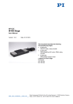
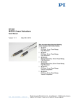
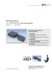
MP47E M-06x Rotation Stage User Manual Version: 2.0.0 Date: 29.05.2015 This document describes the following precision rotation stages (>360°): M-06x.DG: with closed-loop DC gear motor M-06x.PD: with DC motor and PWM control M-06x.2S: with 2-phase stepper motor M-06x.M0: with manual drive x stands for the platform diameter: 0 = 60 mm 1 = 100 mm 2 = 120 mm Physik Instrumente (PI) GmbH & Co. KG, Auf der Roemerstr. 1, 76228 Karlsruhe, Germany Phone: +49 721 4846-0, Fax: +49 721 4846-1019, E-mail: [email protected] Physik Instrumente (PI) GmbH & Co. KG is the owner of the following trademarks: PI®, PIC®, PICMA®, PILine®, PIFOC®, PIMag®, PiezoWalk®, NEXACT®, NEXLINE®, NanoCube®, NanoAutomation®, Picoactuator®, PInano® © 2015 Physik Instrumente (PI) GmbH & Co. KG, Karlsruhe, Germany. The text, photographs and drawings in this manual are protected by copyright. With regard thereto, Physik Instrumente (PI) GmbH & Co. KG retains all the rights. The use of any text, images and drawings is permitted only in part and only when indicating the source. Original instructions First printing: 29.05.2015 Document number: MP47E, MMa, Version 2.0.0 Subject to change without notice. This manual is superseded by any new release. The latest release is available for download (p. 3) on our website. Contents 1 About this Document 1.1 1.2 1.3 1.4 1.5 1.6 2 3 Objective and Target Audience of this User Manual ............................................1 Symbols and Typographic Conventions ...............................................................1 Definition ...............................................................................................................2 Figures ..................................................................................................................2 Other Applicable Documents ................................................................................3 Downloading Manuals ..........................................................................................3 Safety 2.1 2.2 2.3 5 Intended Use ........................................................................................................5 General Safety Instructions ..................................................................................5 Organizational Measures ......................................................................................6 Product Description 3.1 3.2 3.3 3.4 3.5 3.6 3.7 3.8 1 7 Model Overview ....................................................................................................7 Product View.........................................................................................................9 Product Labeling .................................................................................................10 Direction of Motion ..............................................................................................11 Scope of Delivery ...............................................................................................12 Accessories ........................................................................................................12 Suitable Controllers ............................................................................................13 Technical Features .............................................................................................13 3.8.1 Encoder ............................................................................................13 3.8.2 Reference Point Switch ....................................................................13 3.8.3 Integrated PWM Amplifier .................................................................14 4 Unpacking 15 5 Installation 17 5.1 General Notes on Installation .............................................................................17 5.1.1 Notes on all Models ..........................................................................17 5.1.2 Notes on Models with a Motor ..........................................................18 5.2 5.3 5.4 5.5 5.6 5.7 6 Start-Up 6.1 6.2 7 Optional: Modifying the Connection Orientation on the M-06x ...........................18 Optional: Aligning the Hole Pattern of the Platform ............................................20 Mounting the M-06x on a Surface ......................................................................22 Affixing the Load to the M-06x ............................................................................23 Connecting the Motor Cable to the M-06x ..........................................................25 Connecting the Power Supply to the M-06x .......................................................26 27 General Notes on Start-Up .................................................................................27 Starting Up the Rotation Stage ...........................................................................29 6.2.1 M-06x Entries in the Stage Database of PI ......................................30 6.2.2 Operating Parameters of the Models with DC Motor ........................30 6.2.3 Operating Parameters of the Models with Stepper Motor ................31 Maintenance 7.1 7.2 7.3 33 General Notes on Maintenance ..........................................................................33 Performing a Maintenance Run ..........................................................................33 Cleaning the M-06x ............................................................................................34 8 Troubleshooting 35 9 Customer Service 37 10 Technical Data 39 10.1 10.2 10.3 Specifications......................................................................................................39 10.1.1 Data Table ........................................................................................39 10.1.2 Maximum Ratings .............................................................................41 10.1.3 Ambient Conditions and Classifications ...........................................41 10.1.4 Reference Point Switch Specifications .............................................41 Dimensions .........................................................................................................42 10.2.1 M-06x.DG / M-06x.PD / M-06x.2S Models .......................................42 10.2.2 M-06x.M0 Models .............................................................................44 Pin Assignment ...................................................................................................46 10.3.1 Sub-D 15 (m) Controller Connection ................................................46 10.3.2 Mini XLR3 (m) Power Supply Connection ........................................48 11 Old Equipment Disposal 49 12 EC Declaration of Conformity 51 1 About this Document 1 About this Document In this Chapter Objective and Target Audience of this User Manual ..................................................... 1 Symbols and Typographic Conventions ........................................................................ 1 Definition ........................................................................................................................ 2 Figures ........................................................................................................................... 2 Other Applicable Documents ......................................................................................... 3 Downloading Manuals ................................................................................................... 3 1.1 Objective and Target Audience of this User Manual This user manual contains the information needed for the intended use of the M-06x. The stages of the M-060, M-061 and M-062 series are summarized under the designation M-06x in this manual. (x stands for the platform diameter here. Details can be found in the model overview (p. 7)). Basic knowledge of servo systems, motion control concepts and applicable safety measures is assumed. The latest versions of the user manuals are available for download (p. 3) on our website. 1.2 Symbols and Typographic Conventions The following symbols and typographic conventions are used in this user manual: NOTICE Dangerous situation If not avoided, the dangerous situation will result in damage to the equipment. Actions to take to avoid the situation. INFORMATION Information for easier handling, tricks, tips, etc. M-06x Rotation Stage MP47E Version: 2.0.0 1 1 About this Document Symbol/Label Meaning 1. Action consisting of several steps whose sequential order must be observed 2. Action consisting of one or several steps whose sequential order is irrelevant List item p. 5 Cross-reference to page 5 RS-232 Labeling of an operating element on the product (example: socket of the RS-232 interface) Warning sign on the product which refers to detailed information in this manual. 1.3 Definition Term Explanation Load capacity Maximum load capacity in the vertical direction when the rotation stage is mounted horizontally. The contact point of the load is in the center of the platform. Incremental position sensor Sensor (encoder) for capturing changes of position or changes of angle. Signals from the incremental position sensor are used for axis position feedback. After switching on the controller a reference point definition must be performed before absolute target positions can be commanded and reached. 1.4 Figures For better understandability, the colors, proportions and degree of detail in illustrations can deviate from the actual circumstances. Photographic illustrations may also differ and must not be seen as guaranteed properties. 2 Version: 2.0.0 MP47E M-06x Rotation Stage 1 About this Document 1.5 Other Applicable Documents The devices and software tools which are mentioned in this documentation are described in their own manuals. Product Document C-863.11 DC Motor Controller MS205E User Manual C-663.11 Stepper Motor Controller MS208E User Manual C-843 DC Motor Controller PCI Board MS77E User Manual C-884 DC Motor Controller MS213E User Manual Stages with electric motors MP119EK Short Instructions 1.6 Downloading Manuals INFORMATION If a manual is missing or problems occur with downloading: Contact our customer service department (p. 37). INFORMATION For some products (e.g. Hexapod systems and electronics that are delivered with a CD), access to the manuals is password-protected. The password is stored on the CD. Availability of the manuals: Password-protected manuals: FTP download directory Follow the corresponding instructions for downloading. Freely available manuals: PI website Downloading freely accessible manuals 1. Open the website http://www.pi-portal.ws. 2. Click Downloads. 3. Click the corresponding product category. 4. Go to the corresponding product code. The available manuals are displayed. 5. Click the desired manual and save it on the hard disk of your PC or on a data storage medium. M-06x Rotation Stage MP47E Version: 2.0.0 3 1 About this Document Downloading password-protected manuals 1. Insert the product CD in the PC drive. 2. Switch to the Manuals directory on the CD. 3. In the Manuals directory, open the Release News (file including releasenews in the file name). 4. Find the user name and the password in the section "User login for software download"in the Release News. 5. Open the FTP download directory (ftp://pi-ftp.ws). − Windows operating systems: Open the FTP download directory in Windows Explorer. 6. Log in with the user name and the password from the Release News. 7. In the directory of the corresponding product, go to the Manuals sub-directory. 8. Copy the desired manual to the hard disk of your PC or to a data storage medium. 4 Version: 2.0.0 MP47E M-06x Rotation Stage 2 Safety 2 Safety In this Chapter Intended Use ................................................................................................................. 5 General Safety Instructions ........................................................................................... 5 Organizational Measures............................................................................................... 6 2.1 Intended Use The M-06x is a laboratory device as defined by DIN EN 61010. It is intended for indoor use and use in an environment that is free of dirt, oil and lubricants. In accordance with its design and realization, the M-06x is intended for single-axis positioning, adjusting and shifting of loads at different velocities. The M-06x is not intended for applications in areas in which a failure would present severe risks to human beings or the environment. The M-06x is intended for horizontal or vertical mounting. For the load limits with vertical mounting, see "General Notes on Installation" (p. 17). The intended use of the M-06x is only possible when completely mounted and connected. The M-06x must be operated with a suitable controller (p. 13). The controller is not included in the scope of delivery of the M-06x. 2.2 General Safety Instructions The M-06x is built according to state-of-the-art technology and recognized safety standards. Improper use can result in personal injury and/or damage to the M-06x. Only use the M-06x for its intended purpose, and only use it if it is in a good working order. Read the user manual. Immediately eliminate any faults and malfunctions that are likely to affect safety. The operator is responsible for the correct installation and operation of the M-06x. M-06x Rotation Stage MP47E Version: 2.0.0 5 2 Safety 2.3 Organizational Measures User manual Always keep this user manual available with the M-06x. The latest versions of the user manuals are available for download (p. 3) on our website. Add all information given by the manufacturer to the user manual, for example supplements or technical notes. If you give the M-06x to other users, also include this user manual as well as other relevant information provided by the manufacturer. Only use the device on the basis of the complete user manual. Missing information due to an incomplete user manual can result in damage to equipment. Only install and operate the M-06x after you have read and understood this user manual. Personnel Qualification The M-06x may only be installed, started up, operated, maintained and cleaned by authorized and appropriately qualified personnel. 6 Version: 2.0.0 MP47E M-06x Rotation Stage 3 Product Description 3 Product Description In this Chapter Model Overview ............................................................................................................. 7 Product View ................................................................................................................. 9 Product Labeling .......................................................................................................... 10 Direction of Motion ....................................................................................................... 11 Scope of Delivery ........................................................................................................ 12 Accessories ................................................................................................................. 12 Suitable Controllers ..................................................................................................... 13 Technical Features ...................................................................................................... 13 3.1 Model Overview Classification of the stages The stages of the M-060, M-061 and M-062 series are summarized in this manual under the designation M-06x. All models are precision rotation stages with backlash-compensated worm drives and a continuous travel range in both directions of rotation. They differ with respect to: Platform diameter Drive type Model Platform diameter [mm] 60 M-060.xx 100 + M-061.xx + M-062.xx M-06x Rotation Stage 120 + MP47E Version: 2.0.0 7 3 Product Description Model Drive type DC motor Stepper motor Manual Direct drive, PWM M-06x.PD Gearhead, analog + M-06x.DG + M-06x.2S + M-06x.M0 + Detailed model overview Order number Product name M-060.2S Precision Rotation Stage, Ø 60 mm, 360°, 2-Phase Stepper Motor M-060.DG Precision Rotation Stage, Ø 60 mm, 360°, closed-loop DC Gear Motor M-060.M0 Precision Rotation Stage, Ø 60 mm, 360°, Manual Drive M-060.PD Precision Rotation Stage, Ø 60 mm, 360°, ActiveDrive DC Motor M-061.2S Precision Rotation Stage, Ø 100 mm, 360°, 2-Phase Stepper Motor M-061.DG Precision Rotation Stage, Ø 100 mm, 360°, closed-loop DC Gear Motor M-061.M0 Precision Rotation Stage, Ø 100 mm, 360°, Manual Drive M-061.PD Precision Rotation Stage, Ø 100 mm, 360°, ActiveDrive DC Motor M-062.2S Precision Rotation Stage, Ø 120 mm, 360°, 2-Phase Stepper Motor M-062.DG Precision Rotation Stage, Ø 120 mm, 360°, closed-loop DC Gear Motor M-062.M0 Precision Rotation Stage, Ø 120 mm, 360°, Manual Drive M-062.PD Precision Rotation Stage, Ø 120 mm, 360°, ActiveDrive DC Motor For further technical data, see the specifications (p. 39). 8 Version: 2.0.0 MP47E M-06x Rotation Stage 3 Product Description 3.2 Product View Figure 1: Components of the M06x.2S models Figure 3: Components of the M06x.DG models 1 Motor 2 Motor flange 3 Platform 4 Scale ring 5 Base body 6 Controller connection (Sub-D 15 panel plug) 7 Power supply connection (Mini XLR3 panel plug) 8 Handwheel M-06x Rotation Stage MP47E Figure 2: Components of the M06x.PD models Figure 4: Components of the M06x.M0 models Version: 2.0.0 9 3 Product Description 3.3 Product Labeling Figure 5: Position of the product labeling Position Labeling Description 1 Manufacturer's logo 1 CE conformity mark 1 Warning sign "Observe manual!" 1 M-060.PD Product name (example), the places after the point refer to the model 1 113050975 Serial number (example), individual for each M-06x Meaning of the places (counting from left): 1 = internal information, 2 and 3 = manufacturing year, 4 to 9 = consecutive numbers 1 WWW.PI.WS Manufacturer's address (website) 1 10 Old equipment disposal (p. 49) 1 Country of origin: Germany Country of origin 2 0 0° mark in the base body Version: 2.0.0 MP47E M-06x Rotation Stage 3 Product Description Position Labeling Description Graduation on the scale ring of the moving platform (detail) 3 0 180 Short line: 2° Medium line: 10° Long line: 90° and 270° Numbers: 0° and 180° 4 24 VDC Power supply connection (only for M-06x.PD models) 5 Controller Controller connection (only for M-06x.DG, M-06x.PD and M-06x.2S models) 3.4 Direction of Motion Figure 6: Direction of motion of the M-06x.2S (top) and M-06x.PD / M-06x.DG (bottom) models + Direction of motion on positive command 0 0° mark in the base body: After a reference move, the 0° mark on the scale ring of the moving platform is above the 0° mark in the base body. M-06x Rotation Stage MP47E Version: 2.0.0 11 3 Product Description 3.5 Scope of Delivery Item number Component M-06x.xx Rotation stage according to the order (p. 7) MP119EK Short instructions for stages with electric motors Only M-060.xx models: 2493 Screw set for mounting the rotation stage: 6 M4x12 socket head cap screws ISO 4762 Allen wrench AF 3 DIN 911 Only M-061.xx / M-062.xx models: 2498 Screw set for mounting the rotation stage: 6 M4x16 socket head cap screws ISO 4762 Allen wrench AF 3 DIN 911 Only M-06x.DG / M-06x.PD / M-06x.2S models: C-815.38 Motor cable, 3 m, Sub-D 15 (m/f) Only M-06x.PD models: C-663.PS Wide-range-input power supply 24 V / 42 W 3763 Power cord K050B0002 Adapter from 5.5 mm x 2.1 mm barrel connector to Mini XLR3 (f) for the power supply connection 3.6 Accessories Order number Description C-815.83 Motor cable, 10 m, Sub-D 15 (m/f) To order, contact our customer service department (p. 37). 12 Version: 2.0.0 MP47E M-06x Rotation Stage 3 Product Description 3.7 Suitable Controllers For the M-06x.DG, M-06x.PD and M-06x.2S models, the following applies: The M-06x must be connected to a suitable controller. The following controllers from PI are suitable for the operation of the M-06x: Drive type Controller Axes per controller DC motor C-843 2 or 4 Internal (PCI bus) Yes, separate boards C-863 1 USB, RS-232, daisy chain Yes, same interface C-884 1 to 4 USB, RS-232, TCP/IP Yes C-663 1 USB, RS-232, daisy chain Yes, same interface Stepper motor PC interface Multiple controllers on the same PC PC software is included in the scope of delivery of the controllers from PI. The operation of the controllers is described in the corresponding user manuals. 3.8 Technical Features 3.8.1 Encoder The M-06x.DG and M-06x.PD models are equipped with an incremental rotary encoder. For the encoder resolution, refer to the table in the "Specifications" section (p. 39). A rotary encoder is implemented at a rotating point in the drivetrain, e.g. the motor shaft. 3.8.2 Reference Point Switch The M-06x.DG, M-06x.PD and M-06x.2S models are equipped with a directionsensing reference point switch (see "Reference Point Switch Specifications" (p. 41)). The commands that use the reference signal are described in the user manual of the controller and/or in the corresponding software manuals. After a reference move of the M-06x, the 0° mark on the scale ring of the moving platform is above the 0° mark in the base body. M-06x Rotation Stage MP47E Version: 2.0.0 13 3 Product Description 3.8.3 Integrated PWM Amplifier The M-06x.PD models with direct drive are equipped with a PWM amplifier ("ActiveDrive concept"). The PWM amplifier only receives the control signals from the controller, whereas the supply voltage is provided via an external power supply. The ActiveDrive concept allows high motor power and dynamics at low power loss. 14 Version: 2.0.0 MP47E M-06x Rotation Stage 4 Unpacking 4 Unpacking 1. Unpack the M-06x with care. 2. Compare the contents against the items covered by the contract and against the packing list. 3. Inspect the contents for signs of damage. If parts are missing or you notice signs of damage, contact PI immediately. 4. Keep all packaging materials in case the product needs to be returned. M-06x Rotation Stage MP47E Version: 2.0.0 15 5 Installation 5 Installation In this Chapter General Notes on Installation ...................................................................................... 17 Optional: Modifying the Connection Orientation on the M-06x.................................... 18 Optional: Aligning the Hole Pattern of the Platform ..................................................... 20 Mounting the M-06x on a Surface ............................................................................... 22 Affixing the Load to the M-06x ..................................................................................... 23 Connecting the Motor Cable to the M-06x ................................................................... 25 Connecting the Power Supply to the M-06x ................................................................ 26 5.1 General Notes on Installation 5.1.1 Notes on all Models NOTICE Unintentional changes in position with vertical mounting! If the load exceeds the self-locking of the drive when the stage is mounted vertically, unintentional changes in the position of the moving platform occur. Unwanted changes in the position of the moving platform can damage the drive, the load or the environment. When the stage is mounted vertically, make sure that the installed load is lower than the self-locking of the drive. INFORMATION For optimum repeatablity, all components must be firmly affixed to each other. If possible, simulate the rotation stage motions with a mounted load or make suitable calculations to detect collisions or unfavorable center of gravity constellations. If necessary, take suitable constructive measures to avoid collisions and instability in the overall system. M-06x Rotation Stage MP47E Version: 2.0.0 17 5 Installation Avoid or mark danger zones that result from the installation of the rotation stage and the application, in accordance with the legal regulations. 5.1.2 Notes on Models with a Motor NOTICE Cable break! A cable break leads to a failure of the rotation stage. Install the rotation stage so that the cable is not bent or crushed too strongly during operation. M-06x.DG and M-06x.PD models: If you change the connection orientation of the rotation stage (p. 18), avoid overstretching the cable between the motor flange and the motor case. NOTICE Heating up of the M-06x during operation! The heat produced during operation of the M-06x can affect your application. Install the M-06x so that your application is not affected by the dissipating heat. 5.2 Optional: Modifying the Connection Orientation on the M-06x INFORMATION Motor and connections of the M-06x.DG and M-06x.PD models can be rotated around the axis of the motor and fixed at any position. 18 Check whether the connections of the rotation stage are at a position that is suitable for your installation situation. Version: 2.0.0 MP47E M-06x Rotation Stage 5 Installation Figure 7: Optional: Continuous rotation of the motor around its axis Figure 8: Position of the grub screws on the motor flange (left: top side, right: bottom side) M-06x Rotation Stage 1 Grub screw 2 Motor flange 3 Motor case MP47E Version: 2.0.0 19 5 Installation Prerequisites The rotation stage is not mounted on a surface. The rotation stage is not connected to the controller and the power supply. Tools and accessories Allen wrench AF 2 Changing the orientation for connection 1. Turn out the grub screws on the motor flange of the rotation stage (see figure) by a few rotations. 2. Rotate the motor case with the connections to the desired orientation: − Avoid overstretching the cable between the motor flange and the motor case. − Make sure that no cables are crushed or bent at the desired orientation. 3. Tighten the grub screws on the motor flange. 4. Check that the motor case is affixed firmly to the motor flange. 5.3 Optional: Aligning the Hole Pattern of the Platform INFORMATION If necessary, you can change the orientation of the 0° mark to the hole pattern for mounting a load. The change is made by rotating the scale ring on the moving platform. 20 Note the following: Irrespective of how the scale ring is oriented on the moving platform, the 0° mark on the scale ring is always above the 0° mark in the base body of the M-06x after a reference move. Version: 2.0.0 MP47E M-06x Rotation Stage 5 Installation The scale ring is fixed on the moving platform of the M-06x with three grub screws. Figure 9: Position of the grub screws on the scale ring 1 Access to the grub screw 2 Mounting hole for load 3 Scale ring 4 0° mark in the base body Prerequisites M-06x.DG / M-06x.PD / M-06x.2S models: The rotation stage is not connected to the controller and the power supply. Tools and accessories Allen wrench AF 0.9 Aligning the hole pattern of the platform 1. Turn out the three grub screws on the scale ring (see figure) by a few rotations. 2. Rotate the scale ring until it has reached the desired orientation to the hole pattern of the platform. 3. Tighten the grub screws on the scale ring. 4. Check that the scale ring is affixed firmly. M-06x Rotation Stage MP47E Version: 2.0.0 21 5 Installation 5.4 Mounting the M-06x on a Surface NOTICE Warping of the M-06x due to mounting on uneven surfaces! Mounting the M-06x on an uneven surface can warp the M-06x. Warping reduces the accuracy. Mount the M-06x on an even surface. The recommended evenness of the surface is ≤10 µm. For applications with large temperature changes: Only mount the M-06x on surfaces that have the same or similar thermal expansion properties as the M-06x. Figure 10: Position of the holes for mounting the rotation stage on a surface Prerequisites 22 You have read and understood the general notes on installation (p. 17). You have provided a suitable surface (for the required position and depth of the holes for accommodating the screws, see "Dimensions" (p. 42)): − There are three M4 threaded holes. − The evenness of the surface is ≤ 10 µm. Version: 2.0.0 MP47E M-06x Rotation Stage 5 Installation − For applications with large temperature changes: The surface should have the same thermal expansion properties as the M-06x (e.g. surface made of aluminum). You have accounted for the space required to route cables without bending and according to regulations. M-06x.DG / M-06x.PD / M-06x.2S: The rotation stage is not connected to the controller and the power supply. Tools and accessories Mounting accessories, in the scope of delivery (p. 12): − M-060.xx: 3 M4x12 screws − M-061.xx / M-062.xx: 3 M4x16 screws − Allen wrench AF 3 Mounting the rotation stage on a surface 1. Align the rotation stage on the surface so that the corresponding mounting holes in the rotation stage and the surface overlap. 2. Completely screw in the screws into all mounting holes. 3. Check that the rotation stage is affixed firmly to the surface. 5.5 Affixing the Load to the M-06x NOTICE Impermissibly high load on the rotation stage! An impermissibly high load interferes with the motion of the moving platform and can damage the rotation stage. In respect to the mass and mounting type of the load, observe the maximum permissible forces that are allowed to act on the moving platform according to the specification (p. 39). M-06x Rotation Stage MP47E Version: 2.0.0 23 5 Installation NOTICE Screws that are too long! Screws that are inserted too deeply can damage the M-06x. Observe the depth of the mounting holes in the moving platform (p. 42). Only use screws of the correct length for the respective mounting holes. Figure 11: Position of the mounting holes for affixing the load Prerequisites 24 You have read and understood the general notes on installation (p. 17). You have properly attached the rotation stage to a surface (p. 22). M-06x.DG / M-06x.PD / M-06x.2S: The rotation stage is not connected to the controller and the power supply. You have prepared the load so that it can be affixed to the mounting holes on the moving platform: − The distance between the center of gravity of the load and the center of the platform is as small as possible in all directions. − At least two points are provided for mounting the load on the platform (ideally: three attachment points). Version: 2.0.0 MP47E M-06x Rotation Stage 5 Installation Tools and accessories At least 2 M4 screws of suitable length Suitable tools for fastening the screws Affixing the Load 1. Align the load so that the selected mounting holes in the platform can be used to affix it. 2. Use the screws to affix the load on the selected mounting holes in the platform. 3. Check that the load is affixed firmly to the platform of the rotation stage. 5.6 Connecting the Motor Cable to the M-06x Prerequisites You have read and understood the general notes on installation (p. 17). The motor cable is not connected to the controller. Tools and accessories Suitable motor cable from PI, e.g.: − C-815.38 motor cable, 3 m, Sub-D, 15-pin (m/f), in the scope of delivery (p. 12). − C-815.83 motor cable, 10 m, Sub-D, 15-pin (m/f), available as optional accessory (p. 12). Connecting the motor cable to the M-06x 1. Connect the connector (f) of the motor cable to the Sub-D 15-pin panel plug (m) of the rotation stage. 2. Secure the connector (f) with the two integrated screws against being unintentionally pulled out of the rotation stage. M-06x Rotation Stage MP47E Version: 2.0.0 25 5 Installation 5.7 Connecting the Power Supply to the M-06x Connecting a power supply is only necessary for the M-06x.PD models. Prerequisites The power cord is not connected to the power socket. Tools and accessories Supplied components: − 24 V wide-range-input power supply − Adapter for the power supply connection; barrel connector 5.5 mm x 2.1 mm to Mini XLR3 (f) − Power cord If one of the components supplied for connection to the power source has to be replaced: Use a sufficiently measured and certified replacement component. Details: − Power supply: Output 24 V DC, maximum output current 2 A − Power cord: Three wires, cable cross section at least 3 x 0.75 mm (3 x AWG18), maximum length 2 m 2 Connecting the power supply to the M-06x Connect the Mini XLR3 connector (f) of the adapter to the Mini XLR3 panel plug of the M-06x. Connect the barrel connector of the adapter to the barrel connector socket of the power supply. Connect the power cord to the power supply. 26 Version: 2.0.0 MP47E M-06x Rotation Stage 6 Start-Up 6 Start-Up In this Chapter General Notes on Start-Up .......................................................................................... 27 Starting Up the rotation stage ...................................................................................... 29 The instructions and descriptions in this chapter apply to models with a motor (M06x.DG, M-06x.PD, M-06x.2S). 6.1 General Notes on Start-Up NOTICE Damage from collisions! Collisions can damage the rotation stage, the load to be moved and the environment. Make sure that no collisions are possible between the rotation stage, the load to be moved and the environment in the motion range of the rotation stage. Do not place any objects in areas where they can get caught by moving parts. Stop the motion immediately if a controller malfunction occurs. If possible, adapt the travel range limits of your mechanical system in the software that you use for commanding the motion. NOTICE Damage if an incorrect controller is connected! Connecting a rotation stage to an unsuitable controller can cause damage to the rotation stage or controller. Connect a rotation stage with DC motor to a DC motor controller only. Connect a rotation stage with stepper motor to a stepper motor controller only. If you use controllers and software from other manufacturers, check their technical data to make sure that they are suitable before starting up the stage! M-06x Rotation Stage MP47E Version: 2.0.0 27 6 Start-Up NOTICE Operating voltage too high or incorrectly connected! Operating voltages that are too high or incorrectly connected can cause damage to the M-06x. Do not exceed the operating voltage range (p. 41) for which the M-06x is specified. Only operate the M-06x when the operating voltage is properly connected; see "Pin Assignment" (p. 46). NOTICE Damage or considerable wear due to high accelerations! High accelerations can cause damage to or considerable wear on the mechanical system. Stop the motion immediately if a controller malfunction occurs. Determine the maximum velocity for your application. NOTICE Unintentional motions! When the M-06x is being connected to the controller, it can carry out unintentional motions. Defective software or wrong operation of the software can also result in unintentional motions. Do not place any objects in areas where they can get caught by moving parts. Before connecting the M-06x, check whether a macro is defined as the start-up macro in the controller, and cancel the selection of the start-up macro if necessary. INFORMATION The maximum velocity for a rotation stage with a stepper motor should be determined in the application. If the commanded velocity is too high, the stepper motor might stop without the controller detecting this condition. 28 Version: 2.0.0 MP47E M-06x Rotation Stage 6 Start-Up INFORMATION The repeatability of the positioning is only ensured when the reference point switch is always approached from the same side. Controllers from PI fulfill this requirement due to the automatic direction sensing for reference moves to the reference point switch. INFORMATION For models with DC motors: Unsuitable settings made to the servo-control parameters can impair the performance of the M-06x. The consequences of this can be expressed as follows: Oscillations If the performance of the M-06x is not satisfactory, check the settings for the servo-control parameters of your controller. Imprecise approach of the position Settling time is too long 6.2 Starting Up the Rotation Stage Prerequisites You have read and understood the General Notes on Start-Up (p. 27). You have properly installed the stage (p. 17). You have read and understood the user manual of the controller used. You have read and understood the manual of the PC software used. The controller and the required PC software have been installed. All connections on the controller have been set up (see user manual of the controller; the stage is connected via the motor cable). Starting up the rotation stage 1. Only M-06x.PD models: Connect the power cord of the power supply to the power socket. 2. Start up the controller (see user manual of the controller). Configure the controller during start-up using the PC software for the stage used (see user manual of the controller and of the PC software): − M-06x Rotation Stage If you use a controller from PI: Select the entry in the stage database that exactly fits the stage model used (p. 30). MP47E Version: 2.0.0 29 6 Start-Up − If you use a controller from another manufacturer: Enter the parameters into the corresponding PC software that exactly fit the stage model used; see the overview of the operating parameters for DC motor controllers (p. 30) or stepper motor controllers (p. 31). 3. Start a few motion cycles for testing purposes (see user manual of the controller). 6.2.1 M-06x Entries in the Stage Database of PI For controllers from PI, you can select the connected rotation stage from a stage database in the corresponding PC software. The appropriate operating parameters are thus loaded to the controller. You can find a detailed description in the user manual for the controller or in the manual for the PC software used. INFORMATION For models with an analog DC gear motor, the stage database contains entries with the name affix "-PWM". When these entries are used, the controller outputs PWM signals for operating the stage. The PWM signals must be converted into the analog signal for the stage by external electronics (PWM/analog converter and separate amplifier). Only select an entry containing "-PWM" after you have consulted our customer service department (p. 37) and provided suitable external electronics in your application. 6.2.2 Operating Parameters of the Models with DC Motor If you use a DC motor controller from a third-party supplier, it may be necessary to enter operating parameters for adaptation to the rotation stage used. Parameter 30 M-060 model M-061 model M-062 model .DG .PD .DG .PD .DG .PD P term 800 350 260 380 260 450 - I term 300 450 130 150 130 280 - D term 450 500 280 350 280 500 - I limit 2000 2000 2000 2000 2000 2000 - Maximum acceleration 100 1000 100 1000 100 1000 °/s² Version: 2.0.0 MP47E Unit M-06x Rotation Stage 6 Start-Up Parameter M-060 model M-061 model M-062 model Unit .DG .PD .DG .PD .DG .PD Maximum velocity* 16 90 9 90 7.5 90 °/s Maximum velocity* 131742 50000 133388 90000 135859 110000 counts/s Motor gear ratio 29.6:1 29.6:1 Worm gear ratio 50:1 50:1 90:1 90:1 110:1 110:1 Encoder resolution 8233 556 14820 1000 18115 1222 29.6:1 - counts/° * Not recommended for continuous operation 6.2.3 Operating Parameters of the Models with Stepper Motor If you use a stepper motor controller from a third-party supplier, it may be necessary to enter operating parameters for adaptation to the rotation stage used. Parameter M-060.2S M-061.2S M-062.2S Unit Recommended start values: Holding current 200 mA Operating current 600 mA Holding current delay 500 ms Max. motor current 850 mA Max. acceleration 100 °/s Max. velocity 36 20 16 °/s Max. velocity* 18 10 8 °/s 2 Hardware properties: Full steps 400 steps/motor revolution Phase resistance 6.6 ohm Max. phase current, bipolar 850 mA * Recommended for continuous operation M-06x Rotation Stage MP47E Version: 2.0.0 31 7 Maintenance 7 Maintenance In this Chapter General Notes on Maintenance ................................................................................... 33 Performing a Maintenance Run ................................................................................... 33 Cleaning the M-06x ..................................................................................................... 34 7.1 General Notes on Maintenance NOTICE Damage due to improper maintenance! Improper maintenance can lead to misalignment and failure of the M-06x. Only loosen screws according to the instructions in this manual. 7.2 Performing a Maintenance Run Depending on the operating conditions and the period of use of the M-06x, the following maintenance measures are required: Maintenance run The maintenance run serves to distribute the existing lubricant. To evenly distribute the existing lubricant, perform a maintenance run over at least 360° after 500 hours of operation or after 1 year at the latest. If you operate the M-06x continuously over a small working range (<20°), perform a maintenance run over at least 360° every 5000 motion cycles. M-06x Rotation Stage MP47E Version: 2.0.0 33 7 Maintenance Lubrication Under laboratory conditions, the rotation stage only needs extra lubrication in exceptional cases. For continuous industrial use, the lubrication intervals must be defined individually. Do not lubricate the M-06x without consulting our customer service department (p. 37). To lubricate, follow the instructions in the maintenance manual which you can obtain from our customer service department. 7.3 Cleaning the M-06x Prerequisites You have disconnected the rotation stage from the controller and the power supply. Cleaning the rotation stage If necessary, clean the surfaces of the rotation stage with a cloth that is lightly dampened with a mild cleanser or disinfectant. 34 Version: 2.0.0 MP47E M-06x Rotation Stage 8 Troubleshooting 8 Troubleshooting Problem Possible causes Solution Reduced positioning accuracy Warped base body Increased wear due to small motions over a long period of time Only M-06x.DG, M06x.PD and M-06x.2S models: Impairment of the function after system modification Controller has been replaced. Mount the M-06x on an even surface. The recommended evenness of the surface is 10 µm. Perform a maintenance run over at least one rotation of the platform. Controller from PI: M-06x has been replaced with another model. Load the parameters from the stage database that correspond to the combination of controller and M-06x model. Controller from a third-party supplier: Only M-06x.DG, MController and/or power 06x.PD and M-06x.2S supply are incorrectly models: Mechanical connected or defective. system does not move; no operating noise can be heard. M-06x Rotation Stage MP47E Check the operating parameters. Check all connecting cables. Check the controller. If present: Check the power supply of the stage. Version: 2.0.0 35 8 Troubleshooting Problem Possible causes Solution When a controller from PI is Motion error = The difference between the used: There is a motion error current position and the commanded position of the axis. exceeds the specified maximum value in closed-loop operation. For example, motion errors can be caused by malfunctions of the drive or the position sensor of the stage. 1. Read out the error code of the controller in the PC software. If there is a motion error, error code -1024 is output. 2. Check your system and make sure that all axes can be moved safely. 3. Switch on the servo mode in the PC software for the affected axis. For details, see the user manual of the controller. Only M-06x.2S models: The mechanical system no longer moves but generates operating noise. The motor is overloaded by an external load torque or the mass to be driven in the case of strong acceleration or deceleration. The motor skips steps. The information on the current position is lost without the controller recognizing this state. Determine the maximum acceleration and velocity in the application for the rotation stage. If the problem that occurred with your system is not listed in the table above or cannot be solved as described, contact our customer service department (p. 37). 36 Version: 2.0.0 MP47E M-06x Rotation Stage 9 Customer Service 9 Customer Service For inquiries and orders, contact your PI sales engineer or send us an e-mail (mailto:[email protected]). If you have questions concerning your system, have the following information ready: − Product codes and serial numbers of all products in the system − Firmware version of the controller (if present) − Version of the driver or the software (if present) − Operating system on the PC (if present) If possible: Take photographs or make videos of your system that can be sent to our customer service department if requested. The latest versions of the user manuals are available for download (p. 3) on our website. M-06x Rotation Stage MP47E Version: 2.0.0 37 10 Technical Data 10 Technical Data In this Chapter Specifications .............................................................................................................. 39 Dimensions .................................................................................................................. 42 Pin Assignment ............................................................................................................ 46 10.1 Specifications 10.1.1 Data Table M-060.M0 / M-061.M0 / M-062.M0 M-060.PD / M-061.PD / M-062.PD M-060.DG / M-061.DG / M-062.DG M-060.2S / M-061.2S / M-062.2S Rotation Rotation Rotation Rotation Rotation range >360 >360 >360 >360 Integrated sensor – Rotary encoder Rotary encoder -- Sensor resolution – 4000 2000 Design resolution – 32 (0.0018) / 17.5 (0.001) / 15 (0.0008) 2.1 (0.00012) / 1.2 (6.9 x 10⁻⁵) / 0.96 (5.5 x 10⁻⁵) 19.7 (0.0011) / 10.9 (0.00063) / 8.9 (0.00051)* µrad (°) Incremental motion – 32 / 17.5 / 15 6.3 / 6 / 5 40 / 20 / 18* µrad Backlash – 200 / 200 / 240 200 / 200 / 240 200 / 200 / 240 µrad Unidirectional repeatability – 50 / 50 / 60 50 / 50 / 60 50 / 50 / 60 µrad Velocity – 90 16 / 9 / 7.5 36 / 20 / 16 °/s Worm gear ratio 50:1 / 90:1 / 110:1 50:1 / 90:1 / 110:1 50:1 / 90:1 / 110:1 50:1 / 90:1 / 110:1 Gear ratio – – (28/12) 4:1 29.6:1 – Active axes Unit Tolerance Motion and positioning ° cts./rev. min. max. Mechanical properties M-06x Rotation Stage MP47E Version: 2.0.0 39 10 Technical Data M-060.M0 / M-061.M0 / M-062.M0 M-060.PD / M-061.PD / M-062.PD M-060.DG / M-061.DG / M-062.DG M-060.2S / M-061.2S / M-062.2S Unit Tolerance Motor resolution – – – 6400* steps/rev. Load capacity / axial force ±500 / ±550 / ±650 ±500 / ±550 / ±650 ±500 / ±550 / ±650 ±500 / ±550 / ±650 N Torque θX, θY ±6 / ±6 / ±7 ±6 / ±6 / ±7 ±6 / ±6 / ±7 ±6 / ±6 / ±7 Nm max. Torque θZ ±4 / ±6 / ±8 ±4 / ±6 / ±8 ±4 / ±6 / ±8 ±4 / ±6 / ±8 Nm max. Motor type – DC motor, ActiveDrive DC gear motor 2-phase stepper motor** Operating voltage – 24 (PWM) 12 differential 24 V Motor power – 30 3 4.8 W Reference point switch – Hall effect Hall effect Hall effect Operating temperature range -10 to 40 -10 to 40 -10 to 40 -10 to 40 Material Aluminum Aluminum Aluminum Aluminum Mass 0.42 / 1.36 / 2.24 0.94 / 1.88 / 2.76 0.94 / 1.88 / 2.76 0.96 / 1.9 / 2.78 C-863 (single-axis) C-863 (single-axis) C-663 (single-axis) C-843 PCI board, for up to 4 axes C-843 PCI board, for up to 4 axes Drive properties Miscellaneous Recommended controller / driver °C kg Specifications for vacuum versions can differ. * With C-663 stepper motor controller. ** Max. 0.85 A/phase; 400 full steps/rev.. 40 Version: 2.0.0 MP47E M-06x Rotation Stage 10 Technical Data 10.1.2 Maximum Ratings The M-06x rotation stages are designed for the following operating data: Device Maximum operating voltage Operating frequency Maximum power consumption M-06x.DG 12 V 0 Hz 3W M-06x.PD 24 V 0 Hz 30 W M-06x.2S 24 V 0 Hz 4.8 W 10.1.3 Ambient Conditions and Classifications The following ambient conditions and classifications must be observed for the M-06x: Area of application For indoor use only Maximum altitude 2000 m Relative humidity Max. 80 % for temperatures up to 31 °C Linearly decreasing to 50 % at 40 °C Storage temperature -10 °C to 40 °C Transport temperature -10 °C to 40 °C Supply fluctuations Max. ±10 % of the nominal voltage Degree of pollution 2 Degree of protection according to IEC 60529 IP40 10.1.4 Reference Point Switch Specifications Type Magnetic (Hall effect) sensor Supply voltage +5 V/GND, supplied via the motor connector Signal output TTL level M-06x Rotation Stage MP47E Version: 2.0.0 41 10 Technical Data 10.2 Dimensions 10.2.1 M-06x.DG / M-06x.PD / M-06x.2S Models Dimensions in mm. Note that the decimal places are separated by a comma in the drawings . 42 Version: 2.0.0 MP47E M-06x Rotation Stage 10 Technical Data Series M-060 Model PD DG 2S PD DG 2S PD DG 2S A 90 90 90 130 130 130 150 150 150 B 29 29 29 34 34 34 42 42 42 C 25 25 25 30 30 30 38 38 38 D 35 35 35 55 55 55 65 65 65 E 12.5 12.5 12.5 15 15 15 21.5 21.5 21.5 F 70 70 70 110 110 110 130 130 130 G 60 60 60 100 100 100 120 120 120 H 20 20 20 35 35 35 45 45 45 I 50 50 50 90 90 90 110 110 110 J 38 38 38 50 50 50 60 60 60 K 20 20 20 20 20 20 28 28 28 L 39 34 39 39 34 39 39 34 39 M 80.8 83.8 86.5 80.8 83.8 86.5 80.8 83.8 86.5 N 19 15 19.5 19 15 19.5 19 15 19.5 O 59.3 51.3 52.5 59.3 51.3 52.5 59.3 51.3 52.5 P 7 7 7 4.5 4.5 4.5 - - - M-06x Rotation Stage M-061 MP47E M-062 Version: 2.0.0 43 10 Technical Data 10.2.2 M-06x.M0 Models Dimensions in mm. Note that the decimal places are separated by a comma in the drawings . 44 Version: 2.0.0 MP47E M-06x Rotation Stage 10 Technical Data Model M-060.M0 M-061.M0 M-062.M0 A 90 130 150 B 29 34 42 C 25 30 38 D 35 55 65 E 12.5 15 21.5 F 70 110 130 G 60 100 120 H 20 35 45 I 50 90 110 J 38 50 60 K 20 20 28 M-06x Rotation Stage MP47E Version: 2.0.0 45 10 Technical Data 10.3 Pin Assignment 10.3.1 Sub-D 15 (m) Controller Connection Figure 12: Sub-D 15 (m) controller connection, front view M-06x.DG models Pin Signal Direction 1 Not connected - Motor (-) Input Motor (+) Input GND GND Not connected - Not connected - + 5 V (encoder) Input Not connected - Not connected - Reference Output GND GND Encoder A (+) Output Encoder A (-) Output Encoder B (+) Output Encoder B (-) Output 9 2 10 3 11 4 12 5 13 6 14 7 15 8 46 Version: 2.0.0 MP47E M-06x Rotation Stage 10 Technical Data M-06x.PD models Pin Signal Direction 1 Not connected - Not connected - Not connected - GND GND MAGN (PWM magnitude) Input SIGN (PWM sign) Input +5V Input Not connected - Not connected - Reference Output GND GND Encoder A (+) Output Encoder A (-) Output Encoder B (+) Output Encoder B (-) Output 9 2 10 3 11 4 12 5 13 6 14 7 15 8 M-06x Rotation Stage MP47E Version: 2.0.0 47 10 Technical Data M-06x.2S models Pin Signal Direction 1 Motor phase 1A Input Motor phase 1B Input Motor phase 2A Input Motor phase 2B Input Not connected - Not connected - Not connected - Not connected - Not connected - Not connected - +5 V Input Not connected - GND GND Reference Output Not connected - 9 2 10 3 11 4 12 5 13 6 14 7 15 8 10.3.2 Mini XLR3 (m) Power Supply Connection Connecting a power supply is only necessary with the M-06x.PD models. Figure 13: Mini XLR 3 (m) power supply connection, front view 48 Pin Signal Direction 1 GND GND 2 24 V DC supply voltage Input 3 Not connected - Version: 2.0.0 MP47E M-06x Rotation Stage 11 Old Equipment Disposal 11 Old Equipment Disposal In accordance with EU law, electrical and electronic equipment may not be disposed of in EU member states via the municipal residual waste. Dispose of your old equipment according to international, national, and local rules and regulations. In order to fulfil its responsibility as the product manufacturer, Physik Instrumente (PI) GmbH & Co. KG undertakes environmentally correct disposal of all old PI equipment made available on the market after 13 August 2005 without charge. Any old PI equipment can be sent free of charge to the following address: Physik Instrumente (PI) GmbH & Co. KG Auf der Roemerstr. 1 D-76228 Karlsruhe, Germany M-06x Rotation Stage MP47E Version: 2.0.0 49 12 EC Declaration of Conformity 12 EC Declaration of Conformity For the M-06x, an EC Declaration of Conformity has been issued in accordance with the following European directives: 2004/108/EC, EMC Directive 2011/65/EU, RoHS Directive The applied standards certifying the conformity are listed below. EMC: EN 61326-1:2013 Safety: EN 61010-1:2010 RoHS: EN 50581:2012 M-06x Rotation Stage MP47E Version: 2.0.0 51