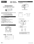
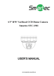
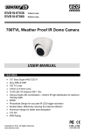
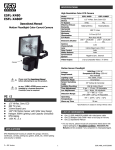
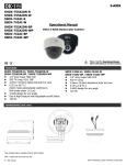
1
EPDX-3540B
EPDX-3540W
ESDX-3420B
ESDX-3420W
540 TVL
540 TVL
420 TVL
420 TVL
Operational Manual
3-AXIS Dome Color Camera
4. Clean the front face to the pick-up device
It is recommended that the pick-up device surface be cleaned
before lens installation or whenever the lens is changed.
Cleaning should be done by using a chamois, a very fine soft
cloth, lens tissue, or cotton tipped applicator and ethanol to
carefully remove any fingerprint or dust.
5. Check the power source voltage
The power source voltage should be within the specified range.
(Camera must meet the specifications). Camera must be
connected to a surge protector at all times.
6. Objects and liquid entry
Never push objects of any kind into this camera as this may
touch dangerous voltage points of short out parts that could
result in a fire or electric shock. Never spill any kind of liquid on
the video product.
7. Servicing
Do not attempt to service this video product by yourself as
opening or removing covers may expose you to dangerous
voltage or other hazards. Refer all service to qualified servicing
personnel.
B = Black
W = White
Please read the Operational Manual
before attempting to use this product.
FEATURES
EPDX-3540B & EPDX-3540W
z
1/3” Sharp CCD, 540 TV Lines
ESDX-3420B & ESDX-3420W
z
1/3” Sony Super HAD CCD, 420 TV Lines
z
z
z
z
3.6mm Board Lens
0.2 Lux @ F2.0
3-AXIS design for any angle
12V DC, 75mA
CAUTION
1. Never point the camera toward the sun
Do not expose the lens directly to the sun or to strong light as this
may damage the pick-up device.
2. Handle this camera with care
Avoid any shock or bumping of the camera. Improper handling
could damage the camera.
3. Requires a proper operating environment
This camera is designed for indoor use. The allowable
temperature range for operation of this camera is between
14°F ~ 122°F / -10°C ~ 50°C and the allowable humidity is
85%RH maximum.
Copyright © 2009. All Rights Reserved.
PAL Version Also Available
8. Damage requiring service
Unplug this video product from the wall outlet and refer service
to qualified servicing personnel under the following conditions:
a. When the power supply cord or plug is damaged.
b. If liquid has been spilled, or objects have fallen into the
video product.
c. If the video product has been exposed to rain or water.
d. If the video product has been dropped or the cabinet has
been damaged.
e. When the video product exhibits a distinct change in
performance.
WARRANTY
Products are covered under warranty for one year from the date of
purchase. The warranty will automatically be voided if any of the
following occurs:
1. Camera sticker is removed
If the camera sticker is removed, we will not be able to confirm
any information regarding when and where the product was
purchased. We have no other way to verify the purchase record
without the serial number on the camera sticker; therefore, it
should not be removed.
2. Camera is modified in any way
If the camera is scratched, damaged, or modified in a manner
not described in this manual, the warranty will be voided
immediately. It is the customer’s responsibility to keep the
camera in good condition.
3. Video or power cable is cut
The video cable and the power cable should not be tampered
with. Cutting or modifying of the cables will result in termination
of the warranty.
REV062309
SPECIFICATIONS
Model
DIMENSIONS
EPDX-3540B EPDX-3540W
Base Color
Black
Image Sensor
ESDX-3420W
Black
White
1/3” Sharp CCD
1/3” Sony Super HAD CCD
Next Chip
Sony
DSP
NTSC: 510(H) x 492(V)
PAL: 500(H) x 582(V)
Total Pixel
Synchronizing
System
Resolution
ESDX-3420B
White
Internal
540 TV Lines
420 TV Lines
Minimum
Illumination
0.2 Lux @ F2.0
S/N Ratio
More than 48dB
Auto Gain Control
White Balance
Gamma
Electronic
Shutter Speed
Video Output
Lens
Auto
Auto
0.45
NTSC: 1/60~1/100,000 sec.
PAL: 1/50~1/100,000 sec.
1Vp-p composite / 75 Ω
3.6mm Board Lens / F2.0
Power Supply
12V DC
Power
Consumption
Operating
Temperature
75mA
14°F ~ 122°F / -10°C ~ 50°C
LIST OF COMPONENTS
z
z
z
One (1) EPDX-3540B or EPDX-3540W or ESDX-3420B or
ESDX-3420W Dome Camera with power/video cable
Four (4) Mounting Screws
One (1) Operational Manual
3.56”(H) x 4.20”(Ø)
90.5mm(H) x 106.8mm(Ø)
Dimension
* Specifications are subject to change without notice
INSTALLATION
1.
Remove the dome cover from the mounting base by
rotating the dome cover clockwise.
2.
Adjust the camera viewing angle by first tilting it, and then
rotate the camera module. Then turn the horizontal
adjustment ring to correct the image and achieve proper
orientation.
3.
Once the installation is complete, replace the dome cover
over the camera and tighten it by turning counter
clockwise.
4.
*Note: Power adapter is sold separately.
Connect the video output to the monitor or other video
device through a 75 Ohm type coaxial cable and the
DC-Jack or AC/DC-Terminator to the power source.
Top
Top
Horizontal
Adjustment
Ring
Tilt
T
Camera
Module
op
Rotate
Copyright © 2009. All Rights Reserved.
PAL Version Also Available
REV062309