1
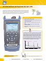
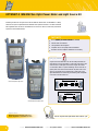
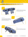
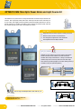
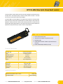
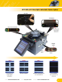
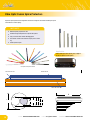
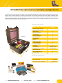
Test and Termination Equipment
About Optronics
About Us
Our History
Optronics is a brand of fibre optic and copper
networking products, for use in local and wide
area networking and telecommunications
applications.
>> Optronics founded in 1974
Since 1974, Optronics has used it’s expertise to
build a comprehensive range of high quality
network communications products which
includes patch cords, pigtails (multimode and
singlemode), patch panels, wall and splice boxes
(unloaded and customised), and a full range of
accessories.
Based in Milton Keynes, UK, we have the facilities
to support a vast array of customers; from small
distributors and supporting specialist installers.
Optronics products are available directly or from
distributors all over the world.
>> Established a Base in Milton Keynes, which is central to all the
major UK national and international transport hubs
>> Moved to a purpose built building in 2002
Our Capabilities
>> Multilingual sales personnel
>> Largest termination capacity in Europe
>> Manufacturing across two continents
>> Several partnerships globally
>> Proactively aiding our clients to secure new and existing
customers through designing and manufacturing bespoke
products in necessary quantites
A Global Company
>> 120 Sales Executives employed
>> 18 Languages spoken
Optronics Global HQ, Milton Keynes, UK
>> 24 hour design and engineering support
capability
>> Global logistics service
>> Regions Covered
North South America
¤
¤
¤
Europe
¤
Africa
Middle East
Australasia
>> Optronics Limited. is registered in England and
has regional offices in each major continent in
the world.
2
www.optronicsnet.com
Regional Office
Global HQ
2 Manufacturing
Locations
Dubai Regional
Office
Regional Office
USA
UK
UAE
China
Optical Test and Termination Equipment
Contents
Fibre Characterisation
OPT-OTDR
Multimode and Singlemode OTDR
4
OPTMSKIT-2
SM + MM Power Meter and Light Source Kit
8
OPTMSKIT-3
SM + MM Power Meter and Light Source Kit
12
OPTSKIT
SM Power Meter and Light Source Kit
14
OPTMKIT-2
MM Power Meter and Light Source Kit
16
OPT-FR
Fibre Ranger
18
OPTVFL
Fibre Optic Pen Style Visual Fault Locator
OPTVFL-MINI
Fibre Optic Mini Visual Fault Locator
21
OPT-OFI
Fibre Optic Live Fibre Identifier
22
OPT-FOTS
Fibre Optic Talk Set
24
OPT-VFIP
Optical Fibre Video Inspection Probe
26
OPT-FHS-200/400
End Face Hand Held Inspection Probe
28
OPT-FSPL-KIT
Fibre Optic Automatic Fusion Splicer
34
OPT-SPLiCE
Fibre Optic Fusion Splice Protectors
38
OPT-CLEAVE77
FIbre Optic Cleaving Tool
40
OPT-COLDKIT
Fibre Optic Cold Cure Termination and Inspection Kit
42
OPT-HEATKIT
Fibre Optic Heat Cure Termination and Inspection Kit
43
OPT-DZCOMPACT
Fibre Optic Compact Dead Zone Eliminator
30
OPT-MTLEAD
Fibre Optic Master Test Leads
32
OPT-CLEANKIT
Fibre Optic Cleaning Kits
41
TOOLS
Fibre Optic Termination Tools
44
CLEANING
Fibre Optic Cleaning and Consumable Products
47
Fibre Validation
Fibre Verification
20
Fibre Inspection
Fibre Termination
Fibre Accessories
click: www.optronicsnet.com
call: +44 (0)1908 441 121
contact: [email protected]
OPT-OTDR Multimode and Singlemode Fibre Optic OTDR
A powerful yet user friendly hand held OTDR specifically designed for testing and trouble-shooting
enterprise, campus and access networks. Test multimode fibre within premises, or singlemode fibre
between premises, with a single OTDR and maximise your return on investment. Improved fibre testing
capability can be achieved with the optional power meter, VFL and inspection probe.
FAST FACTS
Simple, one-touch
“FastTrace”
testingtesting
one-touch
“FastTrace”
> Simple,
> Multiple
Multiple options
including
powerpower
meter, meter,
visual fault
locator
(VFL)
options
including
visual
fault
>
and fiber (VFL)
inspection
locator
andprobe
fiber inspection probe
and and
long battery
life; ideallife;
for ideal
use infor
the
> Robust
Robustconstruction
construction
long battery
field
use in the field
Available inin6 languages:
English,
French,French,
German,German,
Spanish,
> Available
6 languages:
English,
Russian andRussian
Chineseand Chinese
Spanish,
thethe
OTDR
or transfer
direct todirect
USB memory
>
> Store
Storeresults
resultson on
OTDR
or transfer
to USB
stick
or
PC
memory stick or PC
DID YOU KNOW
dBm
An OTDR requires a launch fibre (or Deadzone Eliminator) to be added
to the link under test in order to provide an accurate reading of both
insertion loss and back reflection of the near end connector. Inserted
between the OTDR port and the first connector of the link under test,
the launch fibre gives the light time to stabilise before it reaches the
first connector, enabling the OTDR to make an accurate measurement.
A receive fibre should also be placed at the end of the link under test
to accurately measure the performance of the last connector.
OTDR port
First Connector
Launch Fibre
Link Under Test
Last Connector
Receive Fibre
km
OPT-OTDR Multimode and Singlemode
Application
Characterisation and trouble-shooting of enterprise,
campus and access fibre networks
click: www.optronicsnet.com
See our range of Fibre Optic Dead Zone Eliminators on p 30
call: +44 (0)1908 441 121
contact: [email protected]
OPT-OTDR Multimode and Singlemode Fibre Optic OTDR
Infrared Printer Interface
OTDR Port
Multimode testing
OTDR Port
Singlemode Testing
VFL Port
Built-in 650 nm visual fault
location on a universal connector
Power Meter Detector Port
Compatible with almost every connector on the market.
Manually and efficiently perform power and loss testing.
Accurately measure power up to 26 dBm
Top View
View our video at www.optronicsnet.com for more information
On-Screen Trace Analysis
OTDR Reporting Software
Fast acquisition and analysis – generate your OTDR trace in as little
as five seconds, and then easily analyse the result by toggling between
events, getting an instant zoom on the trace. The moveable A & B
markers give you the flexibility to read the power level at any point
along your OTDR trace.
click: www.optronicsnet.com
Download to PC via USB
call: +44 (0)1908 441 121
Pass/Fail and Macrobend Detection – benefit from an instant onscreen test summary that gives clear indication of potentially
problematic fibre links and a clear detection of macrobends.
Versatile reporting software – benefit from high-end reporting
software allowing deeper analysis of the OTDR trace. Transfer results
easily from the OTDR direct to your PC and generate reports choosing
from a number of available formats, even adding in your own custom
logo.
contact: [email protected]
OPT-OTDR Multimode and Singlemode Fibre Optic OTDR
Combine
two testers in
one unit
Power Meter Option
Adding the power meter to the OTDR gives the flexibility of two testers
in one. It can be used in conjunction with an external light source or by
means of looping back the OTDR can be used as both light source and
power meter.
Combine
two testers in
one unit
Visual Fault Locator (VFL) Option
With a 650nm visible red laser the VFL will verify continuity and
polarity of installed links, helping to speed up installation time. Locate
breaks, excessive fibre bends, connectors, splices and ensure that fibre
management is carried out correctly.
Ultra portable
light weight
Inspection Probe Option
The probe allows the user to inspect connector end faces in switches,
routers, patch panels, wall outlets and patchcords. Time is saved by
eliminating the need to access the back of patch panels or to disassemble
hardware devices for inspection. Save and download your image for
documentation.
click: www.optronicsnet.com
call: +44 (0)1908 441 121
contact: [email protected]
OPT-OTDR Multimode and Singlemode Fibre Optic OTDR
Technical Specification
Wavelength
Dynamic Range
Event Dead Zone
Attenuation Dead Zone
Sampling Points
Distance Range
Internal Memory
OTDR Port Connector
Size (H x W x D)
Weight
Operating Temperature
Battery
MULTIMODE
850/1300nm
20/20dB
3.5m
12/12m
SINGLEMODE
1310/1550nm
25/24dB
3m
12/13m
Over 30,000
5km
50km
500 Results
SC
250mm x 125mm x 75mm
1kg
-18 °C to 50°C
2 x Li-ion batteries 8 hours continuous use
USB B
For data transfer using ActiveSync
USB A
For data transfer using memory stick
Fibre Inspection Probe port
Ordering Information
DESCRIPTION
Quad wavelength MM & SM auto OTDR. Power supply, soft case, SC connectors
Quad wavelength MM & SM auto OTDR. Power supply, soft case, including power meter option.
SC connectors
Quad wavelength MM & SM auto OTDR. Power supply, soft case, including visual fault locator
option. SC connectors
Quad wavelength MM & SM auto OTDR. Power supply, soft case, including power meter and
visual fault locator options. SC
Quad wavelength MM & SM auto OTDR. Power supply, soft case, including visual fault locator and
power meter options with x400 fibre inspection probe and software. SC connectors
Part No.
OPT-OTDR -XX
OPT-OTDR-PRO-XX
Quad wavelength MM & SM auto OTDR. Power supply, soft case, including visual fault locator and
power meter options with x200/400 fibre inspection probe and software. SC connectors
OPT-OTDR-PRO24-XX
Pass/Fail and Macrobend Fault FInder Software (when ordered with OTDR)
Pass/Fail and Macrobend Fault Finder Software Upgrade (when ordered after OTDR)
Optronics ST Connector Adapter for OTDR Port
Optronics SC Connector Adapter for OTDR Port
Optronics FC Connector Adapter for OTDR Port
Optronics x400 Inspection Probe for OTDR, includes software and connection lead
Optronics x200/x400 Inspection Probe for OTDR, includes software and connection lead
Optronics OTDR UK Power Adapter
Optronics OTDR EU Power Adapter
Optronics rechargeable battery for OTDR (2 required)
Optronics Test Soft Case (OTDR)
OPT-OTDR calibration charge for OTDR
OPT-OTDR-P calibration charge for OTDR with power meter
Extended warranty for OPT-OTDR + 1year
Extended warranty for OPT-OTDR + 2year
Extended warranty for OPT-OTDR + 3year
OPT-OTDR-SK1
OPT-OTDR-SK1-UPG
OPT-OTDR-ADPT-ST
OPT-OTDR-ADPT-SC
OPT-OTDR-ADPT-FC
OPT-OTDR-PROBE-4
OPT-OTDR-PROBE-24
OPT-OTDR-AC-UK
OPT-OTDR-AC-EU
OPT-OTDR-BAT
OPT-SOFTCASE-A
OPT-OTDR-CAL1
OPT-OTDR-CAL2
OPT-OTDR-WAR1
OPT-OTDR-WAR2
OPT-OTDR-WAR5
OPT-OTDR-P-XX
OPT-OTDR-V-XX
OPT-OTDR-VP-XX
xx = UK, EU or US power supply
click: www.optronicsnet.com
call: +44 (0)1908 441 121
contact: [email protected]
OPTMSKIT-2 MM+SM Fibre Optic Power Meter and Light Source Kit
Combining the OPT-ELS-100 Light Source and OPT-EPM-500 Power Meter, the OPTMSKIT-2 is ideally
suited for fibre optic link qualification and validation within premises networks. Test both multimode
and singlemode fibre with one kit, download the test results via USB to PC and create professional
reports with the included software.
FAST FACTS
capacityone-touch
for 1000 data
items
> Simple,
“FastTrace”
testing
> Memory
> Multiple
with LEDoptions
indicators
including power meter, visual fault
> Pass/Fail
locator (VFL)
and fiber inspection probe
and recognition
> Tone generation
> Robust construction and long battery life; ideal for
> Complete test kit with jumper leads and mandrels
use in the field
Available in 6 languages: English, French, German,
Spanish, Russian and Chinese
> Store results on the OTDR or transfer direct to USB
DID YOUmemory
KNOWstick or PC
> Numerous connector adapters available for true flexibility
>
A Light Source and Power Meter set will accurately determine the
total amount of loss or attenuation in a fibre span under test. At one
end of the fibre, a stable light source emits a signal that consists
of a continuous wave at a specific wavelength. At the other end, an
optical power meter detects and measures the power level of that
signal. In very general terms, the difference in power level of the
signal measured at the transmitting and receiving ends corresponds
to the loss of the fibre under test.
Channel
Light Source
Power Meter
OPT-ELS-100 Optical Light Source
Test Cord
Test Cord
Light Source
Test Cord
OPT-EPM-500 Optical Power Meter
Power Meter
Permanent Link
Test Cord
Application
Measuring signal attenuation (power loss)
across singlemode or multimode fibre links.
click: www.optronicsnet.com
See our range of Fibre Optic Master Test Leads on p 32
call: +44 (0)1908 441 121
contact: [email protected]
OPTMSKIT-2 MM+SM Fibre Optic Power Meter and Light Source Kit
Instant Pass/Fail Indication
Set up pass/fail thresholds for all wavelengths either for
loss in dB or for power in dBm. A clear LED will give an
instant indication of whether the link under test has passed
(green light) or failed (red light), allowing for quick and easy
identification of problem fibres.
FAIL
PASS
View our video at www.optronicsnet.com for more information
Download to PC via USB
OPTMSKIT Reporting Software
Produce professional-looking reports with the OPTMSKIT-2’s
reporting software. Results stored on the power meter can be
easily and quickly downloaded to your PC via the USB cable
supplied. Pass/fail thresholds set in the unit are automatically
activated and stored in the report viewer where they can be set
for individual fibres or wavelengths. Two separate files can even
be merged in one test report.
click: www.optronicsnet.com
call: +44 (0)1908 441 121
contact: [email protected]
OPTMSKIT-2 MM+SM Fibre Optic Power Meter and Light Source Kit
Interchangable
adapters
Connectivity
A large range of interchangeable connecter adapters are
available for both the light source and power meter allowing
the user ultimate flexibility in fibre testing.
USB
Connectivity
Data Transfer
Test results can be quickly and easily downloaded direct to
a PC from the power meter USB port. Further analysis of
results and the creation of professional reports are made
possible with the inclusive reporting software.
Mains
Connectivity
Power
Run the testers from their batteries for up to 70 hours or
directly from the mains with the supplied AC plug adapters.
10
click: www.optronicsnet.com
call: +44 (0)1908 441 121
contact: [email protected]
OPTMSKIT-2 MM+SM Fibre Optic Power Meter and Light Source Kit
Technical Specification
Specification a
MODEL b
Central wavelength (nm)
Spectral width c (nm)
Output Power (dBm)
Power stability d
for 8 hours (dB)
Battery life (hours)
(typical)
Warranty
Size (H x W x D)
Weight
Temperature
Relative humidity
Specification b
MODEL b
Detector c
Power range d (dBm)
Wavelength range (nm)
Number of calibrated wavelengths e
Power uncertainly f
Automatic offset
nulling g
Display units
Tone detection
Warm-up period h (min)
Data storage (items)
Battery life (hours) (typical)
Warranty
Size (H x W x D)
Weight
Temperature
Relative humidity
OPT-ELS-100
Singlemode
1310 ± 20
1550 ± 20
≤5
≥ 1/ ≥ 1
Multimode
850 ± 25
1300 + 50/-10
50/135
≥ -20/ ≥ -20 (62.5/125 µm)
± 0.10
50
Notes :
a. Guaranteed unless otherwise specified
b. All specifications valid at 23°C ± 1 °C, with an FC
connector
c. rms for lasers and FWHM for LEDs; Typical values
for LEDs
d. After 15 minutes warm-up; expressed as ± half
the difference between the maximum and minimum
values measured during this period, with an APC
connector on the power meter
55
1 year
185 mm x 100 mm x 55 mm
(7 1/4 in x 4 in x 2 1/8 in)
0.4 kg
operating -10°C to 50°C
storage -40°C to 70°C
0% to 95 % non-condensing
SC Connector Adapter for OPT-ELS-100
OPT-EPM-500
Germanium
10 to -70
800 to 1650
6
± 5 % ± 0.1 nW
0.01
dB/dBm/W
270 Hz,1 kHz, 2 kHz
0
Up to 1000
70
1 year
185 mm x 100 mm x 55 mm
(7 1/4 in x 4 in x 2 1/8 in)
0.4 kg
operating -10°C to 50°C
storage -40°C to 70°C
0% to 95 % non-condensing
Notes :
a. Guaranteed unless otherwise specified
b. All specifications valid at 23°C ± 1 °C, with an FC
connector
c. All specifications valid at 1550 nm and 23°C ± 1
°C, with an FC connector
d. In Cw mode; sensitivity defined as 6 x rms noise
level
e. At 850nm, 1300nm, 1310nm, 1490nm,1550nm and
1625nm; for power > -50 dBm for OPT-EPM-500. For
calibration wavelengths
f. For calibrating wavelengths
g. For power > -40 dBm
h. For a variation of ≤ 0.06 dB at power levels ≥ -40
dBm
LC Connector Adapter for OPT-EPM-500
Ordering Information
Description
Optronics Multimode & Singlemode Optical Test Kit With EU AC Adaptor
Optronics Multimode & Singlemode Optical Test Kit With UK Adaptor
Connector Adaptor for OPT-ELS 100 Light Source
Connector Adaptor for OPT-EPM 500 Power meter
Pack of 10 protective covers
Part No.
OPTMSKIT-2
OPTMSKIT-2/UK
OPT-ELS-100OPT-EPM-500-XX2
OPT-ELS-100-CVR
XX1 = FC, ST, SC, E2000
XX2 = FC, ST, SC, E2000, LC
click: www.optronicsnet.com
call: +44 (0)1908 441 121
contact: [email protected]
11
OPTMSKIT-3 SM+MM Power Meter and Light Source Kit
The OPTMSKIT-3 test kit combines the OPT-EPM-50 optical power meter and OPT-ELS-50 and 50-S
light sources and provides a cost-effective solution for testing both multimode and singlemode fibre
networks. The OPT-EPM-50 power meter offers reference setting function and readings in dB, dBm
and Watts. Added to this are an InGaAs detector and tone recognition for fibre identification. The
battery has the capability to support up to 300 hours use.
With excellent power stability the OPT-ELS-50 and 50-S light sources give the end user the confidence
that they will have reliable loss measurements time and again. The units also offers tone generation
for fibre finding and up to 60 hours of battery life. The OPTMSKIT-3 also comes complete with high
quality jumper leads in 50/125µm, 62.5/125µm and 9/125µm, and 50µm & 62.5µm mandrels. All units
come with SC connector adaptors as standard. ST and FC interchangeable adaptors are available
allowing for increased flexibility.
FAST FACTS
handheld
instrumentstesting
designed for reliable
Simple,rugged
one-touch
“FastTrace”
> Cost> effective,
performance
> Multiple options including power meter, visual fault
function
for direct
loss measurements
> Reference
locator
(VFL)
and fiber
inspection probe
and recognitionand long battery life; ideal for
> generation
Robust construction
> Tone
use in the
field for flexibility
connectors
> Interchangeable
> Available
6 languages:
French, German,
test kit in
with
jumper leads English,
and mandrels
> Complete
Spanish,
Russian
and
Chinese
> Individual cases for each tester, plus a case for accessories
>
Store results on the OTDR or transfer direct to USB
memory stick or PC
OPT-ELS-50
OPT-EPM-50
Standard Accessories
2x SC-SC 62.5/125 1.5m Simplex Jumper Lead,
2x SC-SC 50/125 1.5m Simplex Jumper Lead,
2x SC-SC 9/125 1.5m Simplex Jumper Lead,
1 x 62.5/125 mandrel wrap,
1 x 50/125 mandrel wrap,
2 Carrying Cases, Batteries,
User-manual is available to download on our website
OPT-ELS-50-S
12
click: www.optronicsnet.com
call: +44 (0)1908 441 121
contact: [email protected]
OPTMSKIT-3 SM+MM Power Meter and Light Source Kit
Technical Specification
Specification a
MODEL
b
Central wavelength (nm)
Spectral width (nm)b,c
Output power (dBm)
b,d
Power stability (dB)
Battery life (hours)b
Warranty (year)
Tone generation (Hz)
Size(HxWxD)
Weight
Temperature
Relative humidity
OPT-ELS-50
850 ± 25
1300 + 50/-10
≥40/120
≥-24/ ≥-21
(50/125 μm)
± 0.10
60
1
270, 1k, 2k
188mm x 83 mm x 35 mm
(77/16 in x 3 5/16 in x 1 7/16 in)
0.4 kg (0.9lb)
operating -10°C to 50°C
(14°F to 122°F)
0% to 95% non-condensing
OPT-ELS-50-S
1310 ± 20
1550 ± 20
≤5
Safety
21 CRF 1040.10 and IEC 60825-1:2007
CLASS 1 LASER PRODUCT
≥–5
± 0.10
60
1
270, 1k, 2k
188mm x 83 mm x 35 mm
(77/16 in x 3 5/16 in x 1 7/16 in)
0.4 kg (0.9lb)
operating -10°C to 50°C
(14°F to 122°F)
0% to 95% non-condensing
Notes :
a. All specifications valid at 23°C ± 3°C, with an FC/UPC
connector
b. Typical
c. rms for lasers and -3 dB width for LEDs
d. After 15 minutes warm up; expressed as ± half the difference
between the maximum and minimum values measured over 8
hours.
Specification a
MODEL
OPT-EPM-50
Power meter port
InGaAs
b
Power range (dBm)
Number of calibrated wavelengths c
Power uncertainly d
Resolution (dB)
Display units
Tone detection (Hz)
10 to-60
5
±5%
0.01
dB/dBm/W
270,1k, 2k
Battery life (hours) d
>300
Warranty (year)
1
Size (HxWxD)
188 mm x 83 mm x 35 mm (7 7/16 in x 3 5/16 x 1 7/16 in)
Weight
0.4 kg (0.9 lb)
operating -10°C to 50°C (14°F to 122°F)
storage -40°C to 70°C (-40°F to 158°F)
0% to 95% non-condensing
Temperature
Relative humidity
Notes :
a. All specifications valid at 23°C ±3°C, with an FC/UPC
connector
b. In CW mode
c. Wavelength: 850 nm, 1300 nm, 1310 nm, 1490 nm 1550 nm
d. Typical
Ordering Information
DESCRIPTION
Optronics Multimode and Singlemode Optical Test Kit
DESCRIPTION
Connector Adaptor for OPT-ELS-50
Light Source
Connector Adaptor for OPT-EPM- 50
Power Meter
Protective rubber boot for OPT-ELS-50 Light
Source and OPT-EPM-50 Power Meter
Pack of 10 replacement ceramic sleeves for
OPT-ELS-50 Light Source
click: www.optronicsnet.com
PART NO.
OPTMSKIT-3
PART NO.
OPT-ELS-50-xx
OPT-EPM-50-xx
OPT-EPMELS-50-BOOT
OPT-ELS-50- SLEEVE
call: +44 (0)1908 441 121
XX = either FC, SC or ST
contact: [email protected]
13
OPTMKIT-2 MM Fibre Optic Power Meter and Light Source Kit
The OPTMKIT-2 is the perfect choice for testing multimode fibre links within enterprise and local area
networks. With a high-quality InGaAs power meter measuring in dB, dBm or Watts, and battery life
of up to 300hrs, these rugged instruments guarantee reliable and repeatable performance in the field.
With SC connectivity as standard, the OPTMKIT-2 comes complete with reference jumper leads and
fibre mandrels, giving you all you need to test straight out of the box.
FAST FACTS
designed for“FastTrace”
reliable performance
Simple, one-touch
testing
> Rugged hand-held>instruments
>
Reference
function
for
direct
loss
measurements
Multiple
options
including
power
meter, visual fault
>
andidentification
fiber inspection probe
generation(VFL)
for fibre
> Tone recognition and locator
> Robust construction and long battery life; ideal for
> Interchangeable connector adapters available
>
>
use in the field
Available in 6 languages: English, French, German,
Spanish, Russian and Chinese
Store results on the OTDR or transfer direct to USB
memory stick or PC
DID YOU KNOW
Wrapping your test reference cord five times around a fibre mandrel
ensures a consistent launch condition in line with international
standards when testing multimode fibres. Creating a controlled bend
condition along the fibre in this way removes the less stable, higher
order modes of light which propagate near the fibre cladding, resulting in
increased accuracy and improved repeatability.
OPT-ELS-50 Optical LIght Source
Channel
Light Source
Power Meter
OPT-EPM-50 Optical Power Meter
Test Cord
Test Cord
See our range of Fibre Optic Master Test Leads on p 32
Light Source
Power Meter
Permanent Link
Application
Measuring signal attenuation (power loss)
across multimode fibre links.
14
click: www.optronicsnet.com
Test Cord
call: +44 (0)1908 441 121
Test Cord
contact: [email protected]
OPTMKIT-2 MM Fibre Optic Power Meter and Light Source Kit
Technical Specification
MODEL
Central wavelength (nm)b
Spectral width (nm)b,c
Output power (dBm)
Power stability (dB)b,d
Battery life (hours)b
Warranty (year)
Tone generation (Hz)
Size(HxWxD)
Weight
Temperature
Relative humidity
Specification a
OPT-ELS-50
850 ± 25 1300 + 50/-10
≥ 40/120
≥ -24 (50/125 μm)
± 0.10
45
1
270, 1k, 2k
188mm x 83 mm x 35 mm (77/16 in x 3 5/16 in x 1 7/16 in)
0.4 kg (0.9lb)
operating -10°C to 50°C (14°F to 122°F)
0% to 95% non-condensing
MODEL
Power meter port
Power range b (dBm)
Number of calibrated wavelengths c
Power uncertainly d
Resolution (dB)
Display units
Tone detection (Hz)
Battery life (hours) d
Warranty (year)
Size (HxWxD)
Weight
Temperature
Relative humidity
Specification b
OPT-EPM-50
InGaAs
10 to-60
5
±5%
0.01
dB/dBm/W
270,1k, 2k
> 300
1
188 mm x 83 mm x 35 mm (7 7/16 in x 3 5/16 x 1 7/16 in)
0.4 kg (0.9 lb)
operating -10°C to 50°C (14°F to 122°F)
storage -40°C to 70°C (-40°F to 158°F)
0% to 95% non-condensing
Safety
21 CRF 1040.10 and IEC 60825-1:2007
CLASS 1 LASER PRODUCT
Notes :
a. All specifications valid at 23°C ± 3°C, with
an FC/UPC connector
b. Typical
c. rms for lasers and -3 dB width for LEDs
d. After 15 minutes warm up; expressed as ±
half the difference between the maximum and
minimum values measured over 8 hours.
Notes :
a. All specifications valid at 23°C ± 3°C, with an
FC/UPC connector
b. In CW mode
c. Wavelength: 850 nm, 1300 nm, 1310 nm, 1490
nm 1550 nm
d. Typical
OPT-EPM-50
Ordering Information
Description.
Multimode Test Kit consisting of OPT-EPM-50 and OPT-ELS-50
FC Connector adapter for OPT-ELS-50 Light Source
SC Connector adapter for OPT-ELS-50 Light Source
ST Connector adapter for OPT-ELS-50 Light Source
FC Connector adapter for OPT-EPM-50 Power Meter
SC Connector adapter for OPT-EPM-50 Power Meter
ST Connector adapter for OPT-EPM-50 Power Meter
Protective rubber boot for OPT-ELS-50 Light Source and OPT-EPM-50 Power Meter
Pack of 10 replacement ceramic sleeves for OPT-ELS-50 Light Source
click: www.optronicsnet.com
call: +44 (0)1908 441 121
Part No.
OPTMKIT-2
OPT-ELS-50-FC
OPT-ELS-50-SC
OPT-ELS-50-ST
OPT-EPM-50-FC
OPT-EPM-50-SC
OPT-EPM-50-ST
OPT-EPMELS-50-BOOT
OPT-ELS-50-SLEEVE
contact: [email protected]
15
OPTSKIT Singlemode Power Meter and Light Source Kit
The OPTSKIT test kit combines the OPT-EPM-50 optical power meter and OPT-ELS-50-S light source
and provides a cost-effective solution for testing singlemode fibre networks.
The OPT-EPM-50 power meter offers reference setting function and readings in dB, dBm and Watts.
Added to this are an InGaAs detector and tone recognition for fibre identification. The battery has the
capability to support up to 300 hours use.
With excellent power stability the OPT-ELS-50-S light source gives the end user the confidence that
they will have reliable loss measurements time and again. The unit also offers tone generation for
fibre finding and up to 60 hours of battery life.
To complete your testing portfolio, the OPTSKIT also comes complete with high quality jumper leads
in 9/125µm with SC connectors as standard. Both units come with SC adaptors as standard. ST and
FC interchangeable adaptors are available allowing for increased flexibility.
FAST FACTS
rugged
handheld instruments
designed
for reliable performance
Simple,
one-touch
“FastTrace”
testing
> Cost>effective,
function for
direct loss
measurements
> Multiple
options
including
power meter, visual fault
> Reference
locatorand(VFL)
and fiber inspection probe
recognition
> Tone generation
> Robust construction and long battery life; ideal for
> Interchangeable connectors for flexibility
use in the field
Available in 6 languages: English, French, German,
cases for each tester, plus a case for accessories
> IndividualSpanish,
Russian and Chinese
> Store results on the OTDR or transfer direct to USB
memory stick or PC
> Complete test kit with jumper leads
>
Standard Accessories
2x SC-SC 9/125 1.5m Simplex Jumper Lead,
2 Carrying Cases, Batteries, User-manual
is available to download on our website
16
click: www.optronicsnet.com
call: +44 (0)1908 441 121
contact: [email protected]
OPTSKIT Singlemode Power Meter and Light Source Kit
Technical Specification
Safety
Specification a
MODEL
OPT-ELS-50-S
1310 ± 20
1550 ± 20
≤5
≥ –5
± 0.10
60
1
270, 1k, 2k
188mm x 83 mm x 35 mm (77/16 in x 3 5/16 in x 1 7/16
in)
0.4 kg (0.9lb)
operating -10°C to 50°C (14°F to 122°F)
0% to 95% non-condensing
b
Central wavelength (nm)
Spectral width (nm)b,c
Output power (dBm)
Power stability (dB)b,d
Battery life (hours)b
Warranty (year)
Tone generation (Hz)
Size(HxWxD)
Weight
Temperature
Relative humidity
Safety
21 CRF 1040.10 and IEC 60825-1:2007
CLASS 1 LASER PRODUCT
Notes :
a. All specifications valid at 23°C ± 3°C, with an FC/UPC
connector
b. Typical
c. rms for lasers
d. After 15 minutes warm up; expressed as ± half the difference
between the maximum and minimum values measured over 8
hours.
Specification a
MODEL
Power meter port
Power range b (dBm)
Number of calibrated wavelengths c
Power uncertainly d
Resolution (dB)
Display units
Tone detection (Hz)
Battery life (hours) d
Warranty (year)
Size (HxWxD)
Weight
Temperature
Relative humidity
OPT-EPM-50
InGaAs
10 to-60
5
±5%
0.01
dB/dBm/W
270,1k, 2k
>300
1
188 mm x 83 mm x 35 mm (7 7/16 in x 3 5/16 x 1 7/16 in)
0.4 kg (0.9 lb)
operating -10°C to 50°C (14°F to 122°F)
storage -40°C to 70°C (-40°F to 158°F)
0% to 95% non-condensing
Notes :
a. All specifications valid at 23°C ± 3°C, with an FC/UPC
connector
b. In CW mode
c. Wavelength: 850 nm, 1300 nm, 1310 nm, 1490 nm 1550 nm
d. Typical
Ordering Information
DESCRIPTION
Optronics Singlemode Optical Test Kit
PART NO.
OPTSKIT
DESCRIPTION
Connector Adaptor for OPT-ELS-50
Light Source
Connector Adaptor for OPT-EPM- 50
Power Meter
Protective rubber boot for OPT-ELS-50 Light
Source and OPT-EPM-50 Power Meter
Pack of 10 replacement ceramic sleeves for
OPT-ELS-50 Light Source
PART NO.
OPT-ELS-50-xx
OPT-EPM-50-xx
OPT-EPMELS-50-BOOT
OPT-ELS-50- SLEEVE
XX = either FC, SC or ST
click: www.optronicsnet.com
call: +44 (0)1908 441 121
contact: [email protected]
17
OPT-FR Fibre Ranger
The Optronics Fibre Ranger offers the latest in OTDR testing technology in an easy to use portable and
rugged handheld package. With the simple touch of a button, measure the distance of a singlemode
fibre link and locate any potentially problematic reflective and non-reflective (loss) incidents. In seconds
the Fibre Ranger will accurately locate severe bends, breaks, high-loss splices and high-loss connector
interfaces. With no complex data to interpret, on-screen analysis is straightforward allowing for rapid
problem identification.
FAST FACTS
> Portable, rugged and lightweight
Simple,
to useone-touch
- no complex“FastTrace”
OTDR trainingtesting
necessary
> > Easy
Multiple
including power meter, visual fault
up tooptions
8 incidents
> > Locate
locator
(VFL)
and
fiber inspection probe
> Automatic power & pulse width control designed for easy operation
> Robust construction and long battery life; ideal for
> Built-in visual fault locator (VFL)
use in the field
> Dust, water and shock proof, designed for use in the field
>
Available in 6 languages: English, French, German,
>
Store results on the OTDR or transfer direct to USB
memory stick or PC
batteryRussian
life with over
tests
> Long
Spanish,
and5000
Chinese
Battery
Status
Number
of events
Distance
to event
VFL Port
FC/PC Port
Application
Fibre optic link measurement, Location of reflective
and non reflective incidents, fibre repair &
maintenance
Accessories
Soft carry case, 3 x AA batteries, User manual
See our Fibre Optic Dead Zone Eliminator on p 30
18
click: www.optronicsnet.com
call: +44 (0)1908 441 121
contact: [email protected]
OPT-FR Fibre Ranger
Technical Specification
Parameter
Value
Operating Wavelength
1550nm
Fibre Type
9/125µm SM Fibre
Optical Connector Type
FC/PC
Detector Type
InGaAs
Peak Power of Laser
≥60mW
Max. Displaying
Distance
Reflective Event
60km (≥1dB)
Non-reflective Event
20km (≥2.5dB)
Measurement Unit
m
Reflective Event Dead Zone
15m
Distance Accuracy (Reflective Event)
± (2m+2*10(-3)*Distance(m) )
Wavelength of VFL Option
650nm
Output Power of VFL Option
1mW typical
Power Supply
Alkaline Battery (3pcs AA 4.5V Batteries)
Battery Life
≥5000 measurements
Working Temperature Range
-5~40°C
Storage Temperature Range
-10~60°C
Humidity
0~85% (Non-condensating)
Dimensions
190*100*50mm
Weight
450g
Fibre Ranger Complete Test Kit
Order the OPT-FR-KIT and get everything you need to test, troubleshoot, inspect and clean your
singlemode fibre link in one package:
Technical Specification
Parameter
Optronics Fibre Ranger
Optronics Compact Dead Zone Elimator 500m 9/125
Optronics Lint Free Cleaning Tissues
Optronics Soft Black Carry Case
Optronics IPA Cleaning Wipes
Optronics 2.5mm Foam Cleaning Buds
Optronics 1.25mm MicroFibre Cleaning Sticks
FibreCare Connector Cleaning Fluid
FibreCare Fibre Preparation Fluid
Cletop-S Type B Cassette Cleaner
OptronicsTest Fibre Inspection Scope 200x
Value
1
1
100
1
10
100
100
1
1
1
1
Ordering Information
DESCRIPTION
Optronics Fibre Ranger
Optronics Fibre Ranger Complete Test Kit
click: www.optronicsnet.com
PART NO.
OPT-FR
OPT-FR-KIT
call: +44 (0)1908 441 121
contact: [email protected]
19
OPTVFL-2 Pen-style Visual Fault Locator
The OPTVFL-2 is a slim-line, compact visual fault locator, designed to troubleshoot faults on fibre optic
cables. It’s light-weight, pen style makes it ideal for the installer to carry with them on site.
The OPTVFL-2 is an excellent addition to an engineers tool set because it can locate broken fibre
inside the OTDR’s dead-zone. Being portable and light it lends itself to other applications, including
end-to-end continuity checks, identifying connectors in patch panels, and identifying fibres during
splicing operations. The universal connector interface provides fast operation with many connector
styles, without the need to change adapters.
FAST FACTS
>
>
>
>
DID YOU KNOW
>
Simple, one-touch “FastTrace” testing
650nm visible red laser source
> Multiple options including power meter, visual fault
2.5mmlocator
universal(VFL)
connector
interface
for quick connection
and fiber
inspection
probe
Slim
pen-style
with
handy
pocket
clip
> line
Robust construction and long battery life; ideal for
High power
use in(1mW)
the field
> Available in 6 languages: English, French, German,
Spanish, Russian and Chinese
A visual fault locator emits a visible red light
(transmitting at 650nm) that, when directed
through an optical fibre, can help locate breaks or
critical bends. It can also be used to help check
continuity and identify a fibre’s far end.
To Detect Fibre Breaks
Technical Specification
PARAMETER
VALUE
Size (L x d)
Weight
Connector type
Power
Operating temperature
Storage temperature
Emitter type
Wavelength:
Output power
Modulation
170mm x 13.5mm
88g (including batteries)
Universal 2.5mm adapter
2 AA alkaline batteries (40 hours typical)
0 to 40°C, 95% humidity non condensing
-20 to 60°C, 95% humidity non condensing
Class 2 Laser diode
650nm nominal
1 mW (into single-mode fibre)
2 Hz or CW selected
Ordering Information
Performs Continuity Checks
Find Loss Inducing Bends
Optimise Fibre Splices
Description
Part No.
Optronics Pen-style Visual Fault Locator
1.25 Adaptor available
20
Identify Defective
Connectors
OPTVFL-2
OPTVFL-2-ADPT1.25
click: www.optronicsnet.com
call: +44 (0)1908 441 121
contact: [email protected]
OPTVFL-MINI Fibre Optic Visual Fault Locator
The OPTVFL-MINI is a powerful pocket-sized visual fault locator, designed to trouble shoot faults on
fibre optic cables. Small enough to easily fit inside an installers pocket or tool belt, it is the ideal
tool to carry on site and have on hand for any emergency.
The OPTVFL-MINI is a necessary addition to an engineers tool set because it can identify breaks,
bends and connector losses inside the OTDR’s dead-zone. Portable and light, it lends itself to other
applications, including end-to-end continuity checks, identifying connectors in patch panels and
identifying fibres during splicing operations. The universal 2.5mm connector interface provides fast
operation with many connector styles, without the need to change adapters.
FAST FACTS
>
Simple, one-touch “FastTrace” testing
> 650nm visible red laser source
> Multiple options including power meter, visual fault
> Truly pocket size, complete with protective soft case
locator (VFL) and fiber inspection probe
(1mW)
> High
> power
Robust
construction and long battery life; ideal for
universal
in theconnector
field interface for quick connection (for
> 2.5mmuse
SC/ST/FC)
> Available in 6 languages: English, French, German,
universalRussian
adapter available
(for LC/MU)
> 1.25mmSpanish,
and Chinese
Technical Specification
general
Connector type
Power
Operating temperature
Storage temperature
Size (H x W x D)
Weight:
optical
Emitter type
Wavelength
Output power
Modulation
optvfl
Universal 2.5mm adapter
2 AA alkaline batteries
-10 to 45°C
-40 to 70°C
100 x 30 x 18mm
60g including batteries
optvfl
Class 2 laser diode
650 nm - 10 nm
1 mW continuous wave
2 Hz or CW selected
Ordering Information
Description
Optronics Mini Visual Fault Locator - 650nm
1.25 Adaptor available
click: www.optronicsnet.com
Part No.
OPTVFL-MINI
OPTVFL-2-ADPT1.25
call: +44 (0)1908 441 121
contact: [email protected]
21
OPT-OFI Fibre Optic Live Fibre Identifier
The OPT-OFI Live Fibre Identifier will check for live network traffic and measure relative power anywhere
on a multimode or singlemode fibre, without having to disconnect it from the network, avoiding any
disruption to service provision. Test either 3mm or 2mm cable and 900µm or 250µm fibre with the
accompanying interchangeable adapters.
OPT-OFI Fibre Optic Live Fibre Identifier
FAST FACTS
> Easy-to-use “ONE KEY” operation
Efficientlyone-touch
identifies the“FastTrace”
traffic direction
and displays the core
testing
> Simple,
power
of
the
fibre
> Multiple options including power meter, visual fault
Detect frequency
tonefiber
wheninspection
used with aprobe
tone generator (270
(VFL) and
> locator
Hz, 1kHz, construction
2kHz)
> Robust
and long battery life; ideal for
Low bending
loss and highly efficient output
> use
in the field
Easy-to-replace
in 6 adaptors
languages: English, French, German,
> Available
Spanish,
Russian
andChinese
quality construction
> Durable metal housingand
19.6 cm
>
Store results on the OTDR or transfer direct to USB
memory stick or PC
DID YOU KNOW
Fibre Identifiers operate by inducing a small macrobend on the fibre. If
there is light present, a small amount will leak from the tiny bend and its
direction of travel and relative power can then be measured. All this can
be done mid-span along the fibre so there is no need to disconnect the
fibre from the network, avoiding any disruption to service. The OPT-OFI
can also detect and identify specific modulated frequencies transmitted
down the fibre.
2.7 cm
Standard Accessories:
4pcs adapter heads, alkaline battery,
user manual, cotton swabs, soft
carrying case
22
click: www.optronicsnet.com
call: +44 (0)1908 441 121
contact: [email protected]
OPT-OFI Fibre Optic Live Fibre Identifier
Technical Specification
PARAMETER
Identified Wavelength Range (nm)
Identified Signal Type (Hz)
Detector Type
Adapter Type
Signal Direction
Single Direction Test Range
(dBm, CW/0.9mm bare fiber)
Signal Power Test Range
(dBm, CW/0.9mm bare fiber)
Signal Frequency Display (Hz)
Frequency Test Range (dBm, Average
Value)
VALUE
800-1700
CW, 270 ±5%, 1k±5%, 2k ±5%
1mm InGaAs 2pcs
250µm (Applicable for Bare Fiber)
900µm (Applicable for 0.9 Cable )
2mm (Applicable for 2.0 Cable )
3mm (Applicable for 3.0 Cable )
Left & Right LED
-46 to 10(1310nm)
-50 to 10(1550nm)
STEP 1
Slide on correct adapter for
the fibre being tested.
-50 to 10
900µm, 2mm,
3mm
250µm
Insertion Loss (dB, Typical Value)
Alkaline Battry (V)
Operating Temperature (°C)
Storage Temperature (°C)
Dimension (mm)
Weight (g)
Warranty (year)
270, 1k, 2k
-30 to 0 (270Hz,1KHz)
-25 to 0 (2KHz)
-25 to 0 (1KHz,2KHz)
-20 to 0 (2KHz)
0.8 (1310nm)
2.5 (1550nm)
9
-10 to 60
-25 to 70
196 x 30.5 x 27
200
1
Ordering Information
STEP 2
Place fibre in the groove of
the adapter head.
STEP 3
DESCRIPTION
Optical Fibre Indentifier
PART NO.
OPT-O-FI
Slide adapter head up using
clamp button.
STEP 4
Place the shade cover over
the LED and fibre.
STEP 5
Take note of result (signal
direction and
power level in dB).
click: www.optronicsnet.com
call: +44 (0)1908 441 121
contact: [email protected]
23
OPT-FOTS Fibre Optic Talk Set
The Optronics OPT-FOTS combines the functions of both a digital optical talk set and a stabilized light
source. Designed for use over singlemode optical fibres in LAN, FTTH & Telecomms networks, the talk
set’s hands-free operation is simple to use and allows for full-duplex voice digital communication with
a high quality connection ensuring a clarity of voice at all times. Compact in size and easy to use,
the Optronics OPT-FOTS is the perfect portable companion for an engineer to carry with them on site
during field testing. The OPT-FOTS can also be used as a stabilised light source with the capability to
modulate the signal for tone generation and detection.
FAST FACTS
>
Full-duplex digital voice communication
Simple, light
one-touch
source
> > Stabilized
>>
>
>
>
>
>
>
>
“FastTrace” testing
Multiplerugged
options
including power meter, visual fault
Portable,
and lightweight
locator
(VFL)
and
fiber inspection probe
Easy to use
Robust
and long battery life; ideal for
Large
LCD construction
display with backlight
use in the field
Long battery life up to 10 hours
Available in 6 languages: English, French, German,
Dust,
water Russian
and shockand
proof,Chinese
designed for use in the field
Spanish,
Store results on the OTDR or transfer direct to USB
memory stick or PC
Application
Telecommunication/CATV project maintenance, aid in
attenuation measurement, Optical communication teaching
and research
24
click: www.optronicsnet.com
call: +44 (0)1908 441 121
contact: [email protected]
OPT-FOTS Fibre Optic Talk Set
Technical Specification
Parameter
Operating Wavelength
Emitter Type
Optical Connector Type
Transmission distance
Dynamic Range
Output Power
Output Stability
Power Supply
Battery Operating Time
Operating Temperature
Storage Temperature
Dimensions
Weight
Value
1310/1550 nm
FP-LD
FC/PC fixed
80 km
40 dB
-5- -7dBm(9/125um), CW or 2KHz, 1KHz,
270Hz Modulation
≤ ±0.05dB
Alkaline battery x 3 or 8.4v power adapter
10hrs
-10 - 60 °C
-25 - 70 °C
192 mm x 102 mm x 50 mm
338 g
Standard Kit Contents
item
quantity
Fibre Optic Talk Set
2
Headset
2
Power Supply Adaptor
2
AA battery
6
User Manual
1
Soft carrying case
2
Ordering Information
DESCRIPTION
Optronics Fibre Optic Talk Set
click: www.optronicsnet.com
PART NO.
OPT-FOTS
call: +44 (0)1908 441 121
contact: [email protected]
25
OPT-VFIP Fibre Optic Video Inspection Probe
The Optronics Video Fibre Inspection Probe (OPT-VFIP) is the perfect tool for ensuring that fibre optic
connector end faces are clean and clear from dirt and contamination; the number one cause of network
failure. The lightweight, compact probe fits comfortably in the palm of the hand and with singlehanded focusing it is easy to establish a clear, sharp image of the connector end face. The probe has
a magnification of 150x and uses coaxial illumination to show a greater level of detail with an optical
resolution of 1.5µm. The rugged handheld video display unit has a 2.5” LCD screen and is operated
using an easy to navigate menu system. The unit accepts SD memory cards for image or video data
storage of contaminated or cleaned connector end faces. The interchangeable inspection tips facilitate
the inspection of both unmated connectors and connectors installed in patch panels or inside hardware
devises.
Image viewed through coaxial illumination
below shows clean connector
downloaded from SD card with time and date of image capture
FAST FACTS
> 150x magnification shows more of the contact area
for better
cleaning“FastTrace”
> Simple,
one-touch
testing
Coaxial illumination
for greater
>
> Multiple
options including
power detail
meter, visual fault
1.5µm optical
resolution
(VFL) and
fiber inspection probe
> locator
> Robust
construction
long battery
life; ideal for
Interchangeable
tipsand
for greater
flexibility
>
use
in the
Image
andfield
video capture facility
>
Available
in
6 languages:
English,
French, German,
and USB card
reader
> 2GB SD card
Spanish, Russian and Chinese
> Rugged, handheld & compact design, built for use in
> Store
results on the OTDR or transfer direct to USB
the field
memory
or PC with rechargeable Li-Ion battery
operation
> Over 8hrsstick
Standard Accessories
Accessory
Probe
Video Display
AC Adaptor
2BG SD card
Tip set (Universal 2.5mm PC male, FC/SC PC
female, LC PC female)
26
Quantity
1
1
11
1
1
click: www.optronicsnet.com
Accessory
USB 2.0 to USB mini cable
User Manual
AV output cable
Earpiece
Softcase with carry strap
call: +44 (0)1908 441 121
Quantity
1
1
11
1
1
contact: [email protected]
OPT-VFIP Fibre Optic Video Inspection Probe
Technical Specification
Probe
Size (LxWxH) (mm)
Weight (g)
Resolution (µm)
Optical Magnification (x)
Viewable area (mm)
Electronic viewfinder
Light Source
Focus control
Connector
Operating temperature (°C)
DISPLAY
Size (LxWxH) (mm)
Weight (g)
Frequency (MHz)
Display Size (inch)
Output Mode
Video Mode
Resolution
Compressed video format
Playing Format
Storage media
Power supply
Battery
Operating time (hrs)
Value
18.6 x 5.2 x 5
170
1.25
12
0.3 x 0.28
1/3 inch black and white CCD
Blue LED
Manual coaxial focus
4PIN
-20 to 50
VALUE
164x100x43
412
2.4
2.5 (960 x 240 LCD)
NTSC / PAL
NTSC / PAL
640 x 480 / 320 x 240
MPEG-4 / AVI
MPEG-4 / AVI / ASF / MOV
SD / MMC / U disk
DC 5v 2A
Lithium battery 1800Mah
≥8
Ordering Information
Description
Part No.
Optronics Handheld Video Fibre Inspection Probe with Image Capture
Adapter for OPT-VFIP - Universal 1.25mm PC Connectors (Male)
OPT-VFIP
OPT-VFIP-1.25
Adapter for OPT-VFIP - ST PC Connectors (Female)
OPT-VFIP-ST
Adapter for OPT-VFIP - MU PC Connectors (Female)
OPT-VFIP-MU
Adapter for OPT-VFIP - 2.5mm APC Connectors (Male)
OPT-VFIP-2.5A
Adapter for OPT-VFIP - FC APC Connectors (Female)
OPT-VFIP-FCA
Adapter for OPT-VFIP - SC APC Connectors (Female)
OPT-VFIP-SCA
Adapter for OPT-VFIP - LC APC Connectors (Female)
OPT-VFIP-LCA
Adapter for OPT-VFIP - E2000 PC Connectors (Female)
Adapter for OPT-VFIP - E2000 APC Connectors (Female)
click: www.optronicsnet.com
call: +44 (0)1908 441 121
OPT-VFIP-E2
OPT-VFIP-E2A
contact: [email protected]
27
OPT-FHS-200/400 Fibre Optic Hand Held Inspection Scope
The OPT-FHS series hand held fibre inspection microscopes are an ideal choice for checking field terminations for fibre end-face
quality. A combination of durable construction, comfortable design, easy operation and quality optics ensures that this tool will
enhance the performance of installation and maintenance staff.
The OPT-FHS scopes are designed with a professional grade coaxial illumination system. This maximises the detail seen by the user,
because the light travels along the same axis as the end face making even fine scratches and contaminates easily visible.
The OPT-FHS series is equipped with a laser attenuation filter for your safety. Laser attenuation filters provide excellent eye
protection. However, they are not a substitute for practising good laser safety. Never attach or view a live fibre with any optical fibre
microscope.
FAST FACTS
> Safety filter for eye protection
> Simple,
one-touchof“FastTrace”
Coaxial illumination
connector endtesting
face
>
> Multiple
options
including power meter, visual fault
High quality
glass optics
>
locator
(VFL)
and
fiber inspection probe
> Anti-slip design, rugged body
>
Robust construction and long battery life; ideal for
>
Available in 6 languages: English, French, German,
Spanish, Russian and Chinese
Store results on the OTDR or transfer direct to USB
memory stick or PC
> Long battery life
use in the field
> 2.5mm & 1.25mm connector adapters included
>
DID YOU KNOW
22.5 cm
Contaminated connectors are the largest single cause of optical link
failure, so end-face inspection is a critical part of fibre installation
and maintenance. Before insertion, all end-faces should be
inspected and, if a connector is being mated to a port, the port
must be inspected also. Only inspecting one side of a connection is
ineffective as contamination inside a port can not only cause damage
but also migrate to the connector being inserted. It is important to
also consider equipment ports as they may well be contaminated
and therefore a source of contamination and damage for test cords.
OPT-FHS-200/400 Fibre Optic Hand Held Inspection Scope
5.8 cm
28
click: www.optronicsnet.com
call: +44 (0)1908 441 121
contact: [email protected]
OPT-FHS-200/400 Fibre Optic Hand Held Inspection Scope
Technical Specification
Parameter
Size (LxWxH) (mm)
Weight (kg)
Magnification
Power
Capacity
LED life (hrs)
Battey Life (hrs)
Value
225x58x27.5
0.63 kg (with batteries)
200x or 400x
3x AAA Alkaline batteries
External SD Card
100,000
32 hours typical use with alkaline batteries
Ordering Information
DESCRIPTION
200x Coaxial illumination hand held fibre scope
400x Coaxial illumination hand held fibre scope
PART NO.
OPT-FHS-200x
OPT-FHS-400x
Soft Carry Case
click: www.optronicsnet.com
call: +44 (0)1908 441 121
contact: [email protected]
29
Fibre Optic Compact Dead Zone Eliminator
The Optronics Test Dead Zone Eliminator is an essential tool for anyone undertaking OTDR testing.
Placed between the OTDR and the link under test, the Dead Zone Eliminator allows for an accurate
reading of both insertion loss and back reflection of the near end connector. Housed in a light,
compact, rugged box, the Optronics Dead Zone Eliminator is available in all major fibre types in lengths
of up to 1km.
FAST FACTS
> 1.5mm tails
of connectors
> Simple,
one-touch “FastTrace” testing
> Choice
lengthsoptions
of 150m including
(MM) and 500m
(SM)
lengths
up to fault
> Multiple
power
meter,
visual
> Standard
1km available
request
locatoron(VFL)
and fiber inspection probe
uninteruppted
link and
- no splicing
> Continuous
> Robust
construction
long battery life; ideal for
usesolution
in the field
> Compact
>
Available
in 6force
languages: English, French, German,
retention
> 50N cable
>
Spanish, Russian and Chinese
Store results on the OTDR or transfer direct to USB
memory stick or PC
DID YOU KNOW
dBm
An OTDR requires a launch fibre (or Deadzone Eliminator) to be added
to the link under test in order to provide an accurate reading of both
insertion loss and back reflection of the near end connector. Inserted
between the OTDR port and the first connector of the link under test,
the launch fibre gives the light time to stabilise before it reaches the
first connector, enabling the OTDR to make an accurate measurement.
A receive fibre should also be placed at the end of the link under test
to accurately measure the performance of the last connector.
OTDR port
Launch Fibre
FC
30
SC
click: www.optronicsnet.com
First Connector
Link Under Test
ST
call: +44 (0)1908 441 121
LC
Last Connector
Recieve Fibre
km
E 2000
contact: [email protected]
Fibre Optic Compact Dead Zone Eliminator
120 ± 1mm
1.5 m
85 ± 1mm
Continuous Uninterrupted Link
Technical Specification
Description
Operating Temperature ( ºC )
Intermateability
Fire Performance
Value
-40 to +85
Compliant with IEC 61754 series
Compliant with IEC 60332-1
Part Number Generator
Connector 1
Connector 2
Soft Case
Fibre Type
FC
FC
FC
FC
OM1
62
FCAPC
FCA
FCAPC
FCA
OM2
50
SC
SC
SC
SC
OM3
OM3
SCAPC
SCA
SCAPC
SCA
OM4
OM4
LC
LC
LC
LC
OS1/2
09
LCAPC
LCA
LCAPC
LCA
G657A1 G657A1
ST
ST
ST
ST
E2000
E2000
DZCOMPACT
E2000 E2000
click: www.optronicsnet.com
call: +44 (0)1908 441 121
contact: [email protected]
31
Fibre Optic Master Test Leads
The Optronics range of Master Test Leads is ideal for high precision and high performance optical test
applications. The test leads are terminated with the highest quality physical contact (singlemode)
A Grade zirconia ferrule connectors. The connectors are manufactured with precision mounting
and polishing techniques which ensure excellent mating characteristics and optimised optical
performance.
FAST FACTS
> Optimised geometry of fibre, cable and connector providing
> Simple,
one-touch
reduced
installation
time and“FastTrace”
cost throughtesting
improved accuracy
and
reliability
of
measurement
> Multiple options including power meter, visual fault
locator
(VFL)
andand
fiber
inspection
probe
to IEC,
EIA-TIA,
Telecordia
performance
> Conforms
requirements
> Robust construction and long battery life; ideal for
ultrafield
tight geometry ITU-T G.652D (LWP)
usewith
in the
> Supplied
singlemode
and
multimode
optical fibres
> Available in 6 languages:
English, French, German,
with FC,Russian
SC, LC, &and
ST high
performance connector
> Available
Spanish,
Chinese
types
to
suit
majority
of
applications
> Store results on the OTDR or transfer direct to USB
in standard
> Available
memory
sticklengths
or PC
62.5/125 OM1
> RoHS, REACH & SvHC compliant
> Optional foam lined storage case for added protection
50/125 OM2 / OM3 / OM4
> Tethered dust caps for protection of the connector end face
> End face geometry, concentricity and IL / RL test report
provided
OS1 / OS2
Cable Specification
CHARACTERISTICS
Cable Material
Strength Member
Crush
Operating Temperature
Secondary Buffer Diameter
(2.0mm, 2.4mm and 3.0mm)
Secondary Buffer Diameter
(1.6mm and 1.8mm)
UNITS
N
C
SIMPLEX
LSZH
Aramid
1000
-20 to 60
µm
900±50
µm
600±50
o
OS1/2 ITU-T G.652D SM – Blue
OM1 62.5/125 – Green
OM2, OM3, OM4 50/125 – Red
Colour
32
click: www.optronicsnet.com
call: +44 (0)1908 441 121
contact: [email protected]
Fibre Optic Master Test Leads
Connector Specification
OPTICAL PERFORMANCE
IL MAX/ Master (Acceptance)
MAX IL/Random
Ave/Master*
Ave/Random*
Return Loss
Concentricity / Eccentricity
Max fibre to ferrule OD finished
product
SINGLEMODE**
0.10 dB
0.20 dB
0.08 dB
0.08 dB
55/65 dB
0.8µm Max /
0.4 µm Max
Apex Offset
Radius of curvature (ST, SC, FC)
50 µm Max
Radius of curvature (LC)
MULTIMODE
0.10 dB
0.25 dB
0.08 dB
0.10 dB
1.5 µm Max /
0.75 µm Max
CONFORMANCE
IEC 61300-3-4
IEC 61300-3-34
IEC 61300-3-4
IEC 61300-3-34
IEC 61300-3-6
50 µm Max
10mm Min / 20mm Max
5mm Min / 12mm Max
Mechanical endurance
500 matings
IEC 61300-2-2
Vibration
10-55 Hz, 0.75 amplitude
IEC 61300-2-1
Drop
Drop height 1m, 5 drops
IEC 61300-2-12
Cable retention
2mm = 70N
IEC 61300-2-4
Cable torsion
1.5kg-2.5 kg
IEC 61300-2-5
* The change in attenuation for all the above listed criteria shall be a maximum of 0.10dB
**APC available on request
Fibre Bend Specification
CHARACTERISTICS
Cladding Diameter
Core/Cladding Concentricity Error
Cladding Non Circularity
Mode Field Diameter (mfd) @ 1310nm
Mode Field Diameter (mfd) @ 1550nm
CHARACTERISTICS
Cladding Diameter
Core Diameter
Core/Cladding Concentricity Error
Cladding Non Circularity
Numerical Aperture
UNITS
µm
µm
%
µm
µm
µm
µm
µm
%
SINGLEMODE
125±0.4
≤0.3
≤0.3
9.0±0.4
10.1±0.5
MULTIMODE OM1
MULTIMODE OM2, OM3, OM4
125±1
125±1
50±1
62.5±1
< 1.0
< 1.0
< 1.0
< 1.0
0.2 ± 0.015
0.275 ± 0.015
Hard Carry Case
Part Number Generator
Master Side
FC
FC
SC
SC
LC
LC
ST
ST
Equipment side
FC
SC
Fibre Type
FC
OM1
1T
SC
OM2/
OM3/
OM4
OS1/OS2
click: www.optronicsnet.com
S
2
L
Fibre
Construction
Cable Diameter
Jacket Type
Simplex
S
2
LSZH
L
Colour
Length (m)
Green OM1
G
1m
1
3T
Red OM2/
OM3/OM4
R
1.5m
1.5
9T
Blue OS1/2
B
2m
2
call: +44 (0)1908 441 121
2mm
TL/Z
contact: [email protected]
Test Lead
33
OPT-FSPL-KIT Fibre Optic Automatic Fusion Splicer
The Optronics OPT-FSPL fusion splicer uses a core-to-core PAS (Profile Alignment System) to provide
the best possible termination of optical fibres. Suitable for use with multimode and singlemode
fibres, as well as DS, NZDS and EDF fibres, users can also configure their own programs enabling
different fibres to be spliced when necessary. Complete with a precision cleave tool and fibre
strippers, all packed in a hard carry case, the OPT-FSPL-KIT is the total splicing package.
FAST FACTS
OPT-FSPL-KIT Fibre Optic Automatic Fusion Splicer
> Core to Core alignment
screen “FastTrace” testing
> Colour
Simple,LCD
one-touch
>
> Multiple
Simultaneous
X andincluding
Y views power meter, visual fault
options
>
locator
(VFL)
and
fiber inspection probe
> Result storage
> Robust construction and long battery life; ideal for
> 8 second splice time
use in the field
> Long battery life (200 splice & heat cycles)
>
>
Available in 6 languages: English, French, German,
Spanish, Russian and Chinese
Store results on the OTDR or transfer direct to USB
memory stick or PC
DID YOU KNOW
Fusion splicing is a method for joining two optical fibre cores by melting
the ends together using an electric arc. Only a splicing machine can
provide the high degree of accuracy and control necessary.
The correct preparation of the fibres is vital to ensure an accurate splice.
Any protective coating must be stripped from each fibre. The fibres
are then cleaned and cleaved using a precision cleave tool, then placed
carefully in to the fusion splicer. The machine first inspects the
end-faces to ensure a satisfactory cleave has been obtained. It then
aligns the cleaned and cleaved cores, applying heat from a controlled
electrical arc to melt the fibre ends before pressing them together.
View our video at www.optronicsnet.com for more information
34
click: www.optronicsnet.com
call: +44 (0)1908 441 121
contact: [email protected]
OPT-FSPL-KIT Fibre Optic Automatic Fusion Splicer
Splice Area
Cooling Tray
Easy to use touch pad keys
Heat Shrink Oven
with adjustable
heating time
Serial Port
for data
transfer
ON/OFF
Switch
Step 1
The two fibres are
brought together
automatically
click: www.optronicsnet.com
Step 2
The cores are aligned
call: +44 (0)1908 441 121
Power from External 12V
Battery
Step 3
Step 4
The fibres are fused together the
loss is estimated in dB
Lift the windshield.
The unit performs a 2N
tension test
contact: [email protected]
35
OPT-FSPL-KIT Fibre Optic Automatic Fusion Splicer
Precision Cleave Tool
The Optronics high precision cleave tool is supplied as standard. The 16 position cleave wheel is
capable of up to 3000 uses per position giving a total of 48000 cleaves before the +wheel needs to
be changed. It can be used with both 250µm and 900µm fibres with a cleave length of 10-20mm.
3 Simple steps to a perfect cleave
Step 2
Step 1
Step 3
Close the cover
Load the stripped fibre into the V-groove
Push through the blade
Packed With Accessories
Hard Carry Case
Tri-Hole Stripping Tool
Splice Cooling Tray
Quick Ref Guide
User Manual
Set of Spare Electrodes
AC Power
36
click: www.optronicsnet.com
Battery
call: +44 (0)1908 441 121
contact: [email protected]
OPT-FSPL-KIT Fibre Optic Automatic Fusion Splicer
Technical Specification
PARAMETER
VALUE
Monitor
Colour LCD, x200 magnification, simultaneous display of X and Y axis
Heater
Internal heat shrink oven
Storage
8000 results
Data Transmission
RS232
Applicable Fibres
SM, MM, DS, NZDS, EDF
Cladding Diameter (µm)
100 to 150
Coating Diameter (µm)
100 to 1000
Fibre Cleave Length (mm)
8-22
Splicing Mode
Average Splice Loss (dB)
Return Loss (dB)
Auto and Manual
0.02(SM), 0.01dB(MM), 0.04(DS), 0.04(NZDS)
Operating Temperature (˚C )
Storage Temperature (˚C )
Relative Humidity ( % )
Protection Sleeve Length (mm)
>60
-25 to +50
-40 to +80
0 to 95 non condensing
20 – 60
Tension Test (N)
Language
Power Supply
Battery
Dimensions (mm)
2.0
English, Spanish, French, Chinese, Korean, Russian
AC 100-240volt, 50/60Hz, 30W
DC 12volt, 25W
Li-LION 12V 10Ah
170 (W) x 140 (H) x 170 (D)
Weight (kg)
3.3
Warranty (year)
1
Ordering Information
DESCRIPTION
Fusion splicer, AC adaptor and power cord, Battery, charger, spare electrodes, cooling tray,
precision cleave tool, buffer stripper, carry case
Precision Cleave Tool
Battery for fusion splicer
Electrodes for fusion splicer
AC power supply for fusion Splicer
12V cable connection to vechle power outlet
Extended warranty for OPT-FSPL + 1year
Extended warranty for OPT-FSPL + 2year
Extended warranty for OPT-FSPL + 3year
click: www.optronicsnet.com
call: +44 (0)1908 441 121
PART NO.
OPT-FSPL-KIT
OPT-FSPL-PCT
OPT-FSPL-BATT
OPT-FSPL-ELEC
OPT-FSPL-PSU
OPT-FSPL-12VC
OPT-FSPL-WAR1
OPT-FSPL-WAR2
OPT-FSPL-WAR3
contact: [email protected]
37
Fibre Optic Fusion Splice Protectors
Optronics’s splice protectors are designed to maintain the strength & environmental stability of optical
fibre cables after fusion splicing.
Fast Facts
> Maintains optical properties of fibre
Provides strength
and “FastTrace”
protection to optical
one-touch
testingfibre splices
> Simple,
> Multiple
Easy to useoptions
and install
without power
damaging
splicevisual fault
including
meter,
>
locator
(VFL)
and
fiber
inspection
probe
> Clear sleeve to allow visual location of splice prior to shrink> Robust
construction and long battery life; ideal for
ing
in the
fieldsplice
Sealant
protects
> use
>
>
Available in 6 languages: English, French, German,
Spanish, Russian and Chinese
Store results on the OTDR or transfer direct to USB
memory stick or PC
Application
Used in fibre optic fusion splicing. Turn to page 26
to see our Optronics Fusion Splicer
Fibre Optic Fusion Splice Protectors
Stainless steel rod
Heat shrink outer tube
EVA Hot Melt fusion tube
L
O.D.
B
A
1.2 1.0
0.8
60
0.5
45
40
35
30
26
25
38
click: www.optronicsnet.com
call: +44 (0)1908 441 121
contact: [email protected]
Fibre Optic Fusion Splice Protectors
Technical Specification
Specifications
Stainless Rod
Shrink Process
Outer Tube
Inner Tube
Construction
Values
301 Grade
Heat to 125ºC / maintain 80 seconds / cool
Cross-linked polyolefin
Ethylene Vinyl Acetate
Outer tube encloses and captures fusion tube and rod. Fusion tube centred in assembly.
Ordering Information
Splice Protector (L)
Tube (A)
Rod (B)
Tube Colour
O.D
Recovered
Length
I.D
Length
O.D
Outer/Inner
2.5±0.2
2.5±0.2
3.0±0.2
2.5±0.2
1.5±0.2
1.5±0.2
1.5±0.2
1.4±0.2
2±0.2
2.5±0.2
2.5±0.2
45±1
60±1
60±1
45±1
25±1
35±1
20±1
26±1
25±1
40±1
30±1
1.2±0.1
1.2±0.1
1.2±0.1
1.2±0.1
0.95±0.1
1.8±0.1
0.95±0.1
0.95±0.1
1.6±0.1
1.6±0.1
1.75±0.1
43±1
58±1
58±1
43±1
23±1
33±1
18±1
23±1
22±1
37±1
27±1
1.0±0.1
1.0±0.1
1.0±0.1
1.0±0.1
0.5±0.1
0.5±0.1
0.5±0.1
0.5±0.1
0.8±0.1
1.2±0.1
1.2±0.1
Clear/Clear
Clear/Clear
Clear/Clear
Various/Various*
Clear/Clear
Clear/Clear
Clear/Clear
Clear/Clear
Clear/Clear
Clear/Clear
Clear/Clear
Packing
PaRT NO.
100/pcs
100/pcs
100/pcs
Call
100/pcs
100/pcs
100/pcs
100/pcs
100/pcs
100/pcs
100/pcs
Splice45Clear
Splice60Clear
Splice60Clear3MM
Splice45Colour
Call the sales team
Call the sales team
Call the sales team
Call the sales team
Call the sales team
Call the sales team
Call the sales team
*Pack Comprises of :
12 individual splices in a single bag. The colour set includes the colours designated in IEC 60304; Blue, Orange, Green, Brown, Grey, White, Red, Black, Yellow,
Violet, Rose and Aqua.
The Optronics portfolio of fIbre assemblies also includes Fibre Optic Pigtails
click: www.optronicsnet.com
call: +44 (0)1908 441 121
contact: [email protected]
39
OPT-CLEAVE77 Fibre Optic Cleaving Tool
The OPT-CLEAVE 77 cleaver is a precision fibre cutting tool, suitable for use with 250µm or 900µm
primary and secondary coated optical fibres with a 125 fibre cladding diameter. The 16 position blade
is capable of performing up to 48000 fibre cleaves before it needs replacing.
Fast Facts
> Easy use
Simple maintenance
> Simple,
one-touch “FastTrace” testing
construction
> Compact
Multiple lightweight
options including
power meter, visual fault
locator
(VFL)
and
fiber
inspection
probe
Built
in
sharps
bin
>
> Robust
and long battery life; ideal for
Controlledconstruction
magnetic action
>
use
in
the
field
> Replaceable long life blade
>
>
Available in 6 languages: English, French, German,
Spanish, Russian and Chinese
Store results on the OTDR or transfer direct to USB
memory stick or PC
DID YOU KNOW
A fibre cleave is initiated by lightly scoring the surface of a fibre using
a precision blade. When the fibre is subsequently pulled or bent the
pressure generates a crack and results in a clean and flat cleave.
OPT-CLEAVE77 Fibre Optic Cleaving Tool
Technical Specification
PARAMETER
Blade lifetime (cleaves)
Maximum cleave angle
Weight (g)
Size (LxWxH) (mm)
Cleave length (mm)
VALUE
48000
75% < 0.5
350
72x81x62
3-20
Hard Carry Case
Ordering Information
DESCRIPTION
Optronics high performance optical fibre cleaver
Replacement blade
40
click: www.optronicsnet.com
call: +44 (0)1908 441 121
PART NO.
OPT-CLEAVE77
OPT-CLEAVE77-BLD
contact: [email protected]
Fibre Optic Cleaning Kits
The Optronics fibre optic cleaning kits combine all the best and most widely used products in one
simple to use package. They contain all the necessary products to competently and professionally
clean fibre optic installations. With 3 levels of kit available it’s easier to choose the right one for
the application.
Fast Facts
> High quality products
levels depending
on “FastTrace”
user application
> 3Simple,
one-touch
testing
kit refill
> Products
Multipleavailable
optionsindividually
includingforpower
meter,
>
>
>
>
visual fault
locator
(VFL)
and
fiber
inspection
probe
Provided in a soft carry case
Robust construction and long battery life; ideal for
use in the field
Available in 6 languages: English, French, German,
Spanish, Russian and Chinese
Store results on the OTDR or transfer direct to USB
memory stick or PC
Fibre Optic Cleaning Kits
Contents
Product Description
Lint Free Cleaning Tissues
2.5mm Foam Cleaning Buds
1.25mm MicroFibre Cleaning Sticks
IPA Cleaning Wipes
FibreCare Connector Cleaning Fluid
FibreCare Fibre Preparation Fluid
Cletop-S Type B Cassette Cleaner
Fibre Inspection Scope 200x
Soft Black Carry Case
KIT Nº1
100 pieces
100 pieces
100 pieces
10 pieces
1 piece
1 piece
--1 piece
KIT Nº2
100 pieces
100 pieces
100 pieces
10 pieces
1 piece
1 piece
1 piece
-1 piece
KIT Nº3
100 pieces
100 pieces
100 pieces
10 pieces
1 piece
1 piece
1 piece
1 piece
1 piece
Part No.
CLEANTISSUE
CLEANBUDS
CLEANSTICK
CLEANWIPES
FCC03M
FPF03M
201-46A/B/WHT
OPT-FHS-200X
OPT-SOFTCASE-B
Ordering Information
DESCRIPTION
Optronics Fibre Optic Cleaning Kit Nº 1
Optronics Fibre Optic Cleaning Kit Nº 2
Optronics Fibre Optic Cleaning Kit Nº 3
click: www.optronicsnet.com
PART NO.
CLEANKIT-L1
CLEANKIT-L2/EU
CLEANKIT-L3/EU
call: +44 (0)1908 441 121
contact: [email protected]
41
OPT-COLDKIT Fibre Optic Cold Cure Termination and Inspection Kit
The Optronics cold cure fibre termination and inspection kit is a much needed and valuable kit for anyone wishing to terminate fibre using the cold cure
methods. This kit is suited to anyone who is competent at terminating fibre. The kit contains the Optronics range of tools (contents listed below) and an
inspection scope also comes as standard. All items are packed in their own cut-foam compartment to keep them safe from damage and are presented in
a robust, virtually indestructible, yet stylish case, ideal for such fragile equipment. Optronics has recently updated and modernised its range of tool kits and
they are a must-have for any installer in the fibre optic industry.
Technical Specification
OPT-COLDKIT Kit
38
cm
48
cm
ITEM
Inspection Scope (x200 mag)
Fibre Optic Stripper (Tri Hole)
Kevlar Scissors
Fibre Optic Crimp Tool
Cable Ringing Tool
Universal Stripping Tool
Carbide Pen Scribe
Fluid Dispenser
Cin Bin
1.25mm Polishing Puck
2.5mm Polishing Puck
1” Yellow Syringe Tips
2ml Syringe
Lint Free Tissue
Lapping Film (0.3 / 1.0 / 5.0µm)
Glass Polishing Plate
Cold Cure Epoxy
Cold Cure Activator
QUANTITY
1
1
1
1
1
1
1
1
1
1
1
3
5
1 pack (100 sheets)
15 (5 of each µm)
1
1
1 (UK) / 2 (EU)
Ordering Information
DESCRIPTION
Cold Cure Kit (UK)
Cold Cure Kit (EU)
42
click: www.optronicsnet.com
call: +44 (0)1908 441 121
PART NO.
OPT-COLDKIT
OPT-COLDKIT/EU
contact: [email protected]
OPT-HEATKIT Fibre Optic Heat Cure Termination and Inspection Kit
The Optronics heat cure fibre termination and inspection kit is a much needed and valuable kit for anyone wishing to terminate fibre using the heat cure
method. This kit is suited to anyone who is competent at terminating fibre. The kit contains the Optronics range of tools (contents listed below) and an
inspection scope also comes as standard. All items are packed in their own cut-foam compartment to keep them safe from damage, and are presented in
a robust, virtually indestructible, yet stylish case, ideal for such fragile equipment. Optronics has recently updated and modernised its range of tool kits and
they are a must-have for any installer in the fibre optic industry.
Technical Specification
cm
48
38
cm
OPT-HEATKIT Kit
ITEM
Inspection Scope (x200 mag)
Fibre Optic Stripper (Tri Hole)
Kevlar Scissors
Fibre Optic Crimp Tool
Cable Ringing Tool
Universal Stripping Tool
Carbide Pen Scribe
Fluid Dispenser
Cin Bin
1.25mm Polishing Puck
2.5mm Polishing Puck
1” Yellow Syringe Tips
2ml Syringe
Lint Free Tissue
Lapping Film (0.3 / 1.0 / 5.0µm)
Glass Polishing Plate
Heat Cure Epoxy (UK only)
Termination Oven
QUANTITY
1
1
1
1
1
1
1
1
1
1
1
5
5
1 pack (100 sheets)
15 (5 of each µm)
1
5
1
Ordering Information
DESCRIPTION
Heat Curing Kit (UK)
Heat Curing Kit (EU) without Epoxy
click: www.optronicsnet.com
call: +44 (0)1908 441 121
contact: [email protected]
Part No.
OPT-HEATKIT
OPT-HEATKIT/EU
43
Fibre Optic Termination Tools
JACKET STRIPPER
UNIVERSAL STRIPPER
Description
Part No.
Jacket Stripper
OPT-CS
Ideal for stripping jackets from backbone cable between 4.5mm and 25mm
in diameter. A small rotating blade accurately splits the circumference of
the jacket, then by flicking a switch, the same blade will rotate 90° and is
used to split the jacket down one side for easy removal.
Description
Part No.
Universal Data Stripper
OPT+UTPS
This tool is ideally used for stripping the jacket from round data cable.
With an adjustable blade it will strip from 3.2mm to 9mm on flat cable,
irregular out of shape cable or even multi-conductor cable.
UTP/STP CYCLOPS STRIPPER
EASY HANDLE STRIPPER
Description
Part No.
Cyclops Stripper
OPT+CYCLOPS
An outer sheath stripper for all types of data, audio and fibre optic
cables. Completely automatic, no adjustments required. For cables up to
11mm in diameter.
Description
Part No.
Easy Handle Stripper
OPT-FOS
This hard wearing, easy to handle fibre optic stripping tool includes three
stripping guides for 2mm outer jacket, 900µm Buffer and 250µm acrylic
coating, safety catch and factory set adjuster.
UNIVERSAL CRIMP TOOL
KEVLAR SCISSORS
Description
Part No.
Fibre Optic Crimp Tool
OPT-FOCT
This professional ratchet-style crimping tool is constructed of solid steel.
The rubber handle provides a firm grip and includes a ratchet mechanism
for consistent crimping.
Crimp Specifications: .78” / .151” / .128” / .78” / .068” / .042”
(4.52 / 3.84 / 3.25 / 2.0 / 1.72 / 1.07mm)
Description
Part No.
Kevlar® Scissors
OPT-KS
These light-weight shears are ideal for cutting the Kevlar® strength
members found in fibre optic cables. Ergonomic, moulded handles provide
comfort for both right and left-handed users. The micro-serrated blade
reduces slipping for a more precise cutting action.
Length: 140mm Weight: 79g.
Kevlar is a registered trademark of DuPont
44
click: www.optronicsnet.com
call: +44 (0)1908 441 121
contact: [email protected]
Fibre Optic Termination Tools
Carbide Pen Cleaver
MILLER Armoured Cable Slitter
Description
Part No.
Carbide Pen Cleaver
OPT-CPC
This well presented pen-style scribe uses a 30° wedge shaped carbide
tip. Its design makes for quick and precise cleaving of optical fibre.
Description
Part No.
Armoured Cable Slitter
ACS
Professional grade tool ideal for slitting the corrugated copper, steel or
aluminium armour layer on fibre feeder, central tube, stranded loose
Tube fibre optic cables and other armoured cables.
ABECO JACKET STRIPPING TOOL
ABECO JACKET STRIPPING TOOL
Description
Part No.
Jacket stripping tool
MK02
This stripper can be used on 4.5 to 28.5mm cable insulations and has an
adjustable cutting depth of 3mm, as well as alternative blade options to
suit different jacket types. Its stripping action is both circumferential and
longitudinal, for the removal of insulation or mid span wires.
Description
Part No.
Jacket stripping tool
MK01A
Designed for precision stripping of a variety of insulation types including
rubber, PVC, nylon, cotton and coaxial cables from 8mm to 25mm
diameter. Its stripping action is both circumferential and longitudinal for
the removal of insulation or mid-span wires.
MILLER FIBRE OPTIC STRIPPER
MILLER DUAL-HOLE FIBRE OPTIC STRIPPER 2
Description
Part No.
Miller V-hole fibre optic strippers
FO103-S
These factory set strippers require no adjustment and prevent scratching
or nicking of optical fibre. All cutting surfaces are precision formed,
hardened, tempered and ground assuring precise buffer removal.
Description
Part No.
Dual-hole fibre optic stripper
FO103-D-J
The FO103-D-J A 140µm diameter hole and V-opening in the blade make
this tool ideal for stripping 250µm buffer coating to expose 125µm cladded
fibre. A second hole strips 2-3mm fibre jackets. It is pre-set at the factory
so no adjustments are needed.
click: www.optronicsnet.com
call: +44 (0)1908 441 121
contact: [email protected]
45
Fibre Optic Termination Tools
MILLER TRI-HOLE FIBRE OPTIC STRIPPER 1
CLAUSS FIBRE OPTIC STRIPPER
Description
Part No.
Tri-hole fibre optic cable stripper
FO103-T-250-J
The tri-hole fibre optic stripper is an exceptional tool, recommended for
stripping 250µm coated loose tube fibre and 900µm buffer tube. This
stripper has a .0055” (0.14mm) laser drilled hole, soft plastic cushioned
handle grip and super accurate hardened stripping jaws ensuring a clean
smooth stripping action.
Description
Part No.
Quality fibre optic cable stripper
CFS-2
The CF2-2 stripper incorporates two holes for stripping fibre optic cable.
The first size accurately removes 250µm coatings and 900µm buffer
tube. The second hole is able to strip cable jackets up to 3mm diameter.
NO-NIK FIBRE OPTIC STRIPPER
MILLER KEVLAR SHEARS
Description
Part No.
NO-NIK 200µm fibre optic stripper
NN203
In a single short stroke the red handle removes 900µm buffer tube and
the 250µm or 500µm fibre coating on tight buffer cable.
Description
Part No.
Kevlar® Shears
KS-1
®
These lightweight shears are perfect for cutting Kevlar strength members.
The blades are made from high carbon molybdenum and vanadium steel
for a long life and a precise neat cut. Kevlar is a registered trademark of
DuPont
RIPLEY MAGNI TWEEZERS
Description
Part No.
Magni tweezers
MT-1
This handy stainless steel tool is specifically suited to fibre optic
applications. Its integral magnifier improves ability to work with small
fibre optic segments.
46
click: www.optronicsnet.com
call: +44 (0)1908 441 121
contact: [email protected]
Cleaning and Consumables Products
Fibre optic MPO cleaner
Description
Part No.
MPO Cleaner
MPOCLEANER1
The MPO / MTP® cleaner is a high-performance device designed for cleaning the ferrule endfaces of MPO / MTP® connectors. This tool cleans the fibre
endface without the use of alcohol, cleaning all 12 fibres at once.
Other Cleaning Brands
KIMWIPES
MICROCARE
CLETOP
CURING OVEN
POLISHING FILMS
Production equipment
POLISHING MACHINES
Other
Our research and development facilities provide us with the engineering expertise for any project. Please contact us for if you have any prospective products
requiring design manufacture or testing, within a short lead time.
click: www.optronicsnet.com
call: +44 (0)1908 441 121
contact: [email protected]
47
Other catalogues available for download at
www.optronicsnet.com
Your local Optronics approved stockist
Optronics Limited
Tel: +44 (0)1908 441 121
www.optronicsnet.com
Version 4.4 Copyright © Optronics 2013 All Rights Reserved E&OE
FFABOPTTESTCAT
is a registered trademark
MTP is a registered trademark of US Conec Ltd.