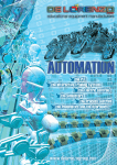
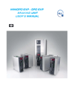
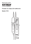
1
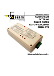
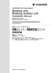
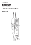
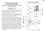
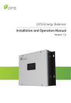
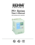
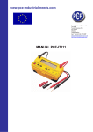
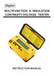
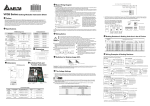
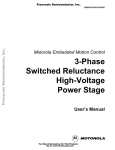
CDBR-B
Dynamic Braking Unit
Instruction Manual
April 2009
Part Number: 146-10001-R1
© Copyright 2009 Electromotive Systems
©2009 MAGNETEK
All rights reserved. This notice applies to all copyrighted materials included with this product, including,
but not limited to, this manual and software embodied within the product. This manual is intended for the
sole use of the persons to whom it was provided, and any unauthorized distribution of the manual or
dispersal of its contents is strictly forbidden. This manual may not be reproduced in whole or in part by any
means whatsoever without the expressed written permission of MAGNETEK.
WA R N I N G
•
Do not touch any circuitry components while the main AC power is on. In addition, you must
wait until the red “CHARGE” LED is out before performing any service on that unit. It may take
as long as 10 minutes for the charge on the main DC bus capacitors to drop to a safe level.
•
Do not check signals during operation.
•
Make sure the unit is set for the appropriate voltage.
•
Make sure to ground the ground terminal.
•
Failure to observe these warnings can result in electrical shock.
A warning label is displayed on the front cover of the braking unit. Follow these instructions when
handling the braking unit.
CDBR-B Installation Instructions
Preface
A Dynamic Braking Unit and Resistor are used to dissipate regenerative energy from the motor. Whenever
an excited motor is operated in the negative slip region or is subjected to an overhauling load, the motor
will behave as an induction generator. In this mode, energy will actually flow from the motor back into the
drive.
This will cause the DC bus voltage to rise. When the DC bus voltage reaches a certain level, the Dynamic
Braking Unit will activate. The Dynamic Braking Unit will shunt the regenerative energy away from the
DC bus capacitors and will dissipate it as heat in the DB resistors. Since the regenerative energy is
dissipated in the resistors, the overvoltage (OV) trip is prevented; thus the motor remains excited and
continues to produce braking torque.
The following Electromotive Systems products can be used with these units:
•
IMPULSE•G
•
IMPULSE•G+
•
IMPULSE•VG+
•
IMPULSE•G+ Series 2
•
IMPULSE•VG+ Series 2
•
IMPULSE•G+ Series 3
•
IMPULSE•VG+ Series 3
Receiving
All equipment is tested against defect at the factory. After unpacking, verify that there is no damage
evident. Report any damage or shortage to the commercial carrier who transported the equipment. Contact
you Electromotive Systems sales representative for assistance.
Storage
If the Dynamic Braking unit is not installed immediately, it must be stored under the following conditions:
•
Ambient temperature: -10 to +40°C
•
Protected from rain and moisture
•
Free from corrosive gases or liquids
•
Free from dust or metal particles
•
Clean and dry
•
Free from excessive vibration
CDBR-B Installation Instructions - April 2009
1-2
Installation
Mounting/Wiring
1. Disconnect all electrical power to the drive.
2. Remove drive front cover.
3. Verify that voltage has been disconnected by using a voltmeter to check for voltage at the incoming
power terminals.
4. The braking unit and braking resistor emit heat during operation. Select a mounting location away
from other heat emitting devices or devices that are heat sensitive. To guarantee proper air-flow for
cooling, the braking unit should not be mounted any closer to external devices than 1.18 in. (30mm) on
either side and 3.94 in. (100mm) of the top and bottom. Select mounting locations so that the wiring
distances between the drive and the braking unit is less than 16.4 feet (5m), and the distance between
the braking unit and the braking resistor is less than 32.8 feet (10m).
5. Make connections between the drive, braking unit(s), and braking resistor(s) according to Figure 1
(single units) or Figure 2 (multiple units).
Grounding
6. The enclosure of the braking resistor should be grounded. If the braking unit cannot be mounted in a
grounded enclosure, ground it by using a lead from the mounting screw of the unit.
7. Grounding resistance of the braking unit should be 100 ohms or less.
8. Use a grounding lead conforming to your National Electric code.
Adjustments
9.
a) It may be necessary to change the appropriate input voltage selection. This determines the
voltage that the dynamic braking unit will turn on. See Figure 3 or 4 and set the jumper to the
nominal three phase supply voltage. Table 1 indicates the DC voltage level that the braking unit
will turn on for different jumper settings. Failure to set the jumper at the nominal voltage can
cause premature failure of the braking unit.
b) If two or more braking modules are applied, ensure that unit #1 is set as the MASTER while the
other unit(s) are set for SLAVE. See Figure 1 or 2 (depending on number of braking modules).
If only one braking unit is applied, verify that the jumper is set to MASTER.
10. The installation of the braking unit may require programming of the drive.
a) For an IMPULSE•G: Program Sn-05 to xx1x, which disables stall prevention during
deceleration.
b) For an IMPULSE•G+: Program Sn-07 to xx1x, which disables stall prevention during
deceleration.
c) For an IMPULSE•G+ Series 2: Program L3-04 to 0, which disables stall prevention during
deceleration.
d) For an IMPULSE•VG+ Series 2: Program L3-04 to 0, which disables stall prevention during
deceleration.
CDBR-B Installation Instructions - April 2009
1-3
Installation
Be sure the CDBR-B is mounted in a location that conforms to the following conditions:
•
Provide at least 3.94 in. (100mm) above and below the CDBR-B.
•
Provide at least 1.18 in (30mm) on either side of the CDBR-B.
•
Provide sufficient space between other components that generate heat or do not tolerate heat.
•
Free from drops of water and corrosive gases.
•
Free of dirt and dust.
•
Free of physical shock and vibration.
Operational Verification
11. During dynamic braking operations, make sure that the required deceleration characteristic is obtained.
The operation indicator (“BRAKE”) lamp in the braking unit lights.
12. Reinstall and secure front covers on the drive and braking units(s).
Table 1: Minimum Resistance Values for Braking Resistors
Supply
Voltage
Turn On
Voltage
200VAC
Minimum Resistance (Ω)
CDBR2022B
CDBR2045-B
CDBR2110B
CDBR4045B
CDBR4090B
CDBR4220B
CDBR5037B
330VDC
5.5
3.3
1.4
–
–
–
–
208VAC
345VDC
5.8
3.5
1.4
–
–
–
–
220VAC
365VDC
6.1
3.7
1.5
–
–
–
–
230VAC
380VDC
6.4
3.8
1.6
–
–
–
–
380VAC
630VDC
–
–
–
10.5
6.3
2.6
–
400VAC
660VDC
–
–
–
11.0
6.6
2.7
–
415VAC
690VDC
–
–
–
11.5
6.9
2.8
–
440VAC
730VDC
–
–
–
12.2
7.3
3.0
–
460VAC
760VDC
–
–
–
12.8
7.6
3.2
–
500VAC
825VDC
–
–
–
–
–
–
20.7
575VAC
950VDC
–
–
–
–
–
–
23.8
Figure 1: Single Unit Wiring Diagram
CDBR-B Installation Instructions - April 2009
1-4
Figure 2: CDBR-B Parallel connection of Braking Unit
CDBR-B Installation Instructions - April 2009
1-5
CDBR-B Parallel Connection Notes
•
Braking units have a MASTER/SLAVE selection jumper (See Figure 2). Select
“MASTER” for Braking Unit 1 and “SLAVE” for all subsequent braking units.
•
Connect thermal protectors on the parallel CDBR-Bs in parallel to the drive’s multi-function
input.
•
Use twisted pair wire, 20 or 22 AWG with ferrules, for connections between terminals 5, 6
and 1, 2 of the CDBR-Bs.
Figure 3: CDBR 2022B, 4045B (Terminal Cover and Indicating Cover Removed)
Figure 4: CDBR-2045B, 2110B, 4090B, 4220B, 5037B (Indicating Cover Removed)
CDBR-B Installation Instructions - April 2009
1-6
CDBR-B Braking Unit Dimensions
"H1"
"H"
4-M4 Mtg. Hole
"W1"
"D"
"W"
Figure 5: CDBR-B Drawing
Table 2: CDBR-B Dimensions
Dimensions in inches (mm)
Model Number
Overall
Wt. in lbs.
(kg)
Mounting
W
H
D
W1
H1
d
CDBR-2022B
5.51 (140)
5.91 (150)
5.45 (138.5)
5.04 (128)
5.43 (138)
.16 (4)
4.56 (2.07)
CDBR-4045B
5.51 (140)
5.91 (150)
5.45 (138.5)
5.04 (128)
5.43 (138)
.16 (4)
4.82 (2.19)
CDBR-B Installation Instructions - April 2009
1-7
d-4 places
H
H1
W1
W
D
Figure 6: CDBR-B Drawing
Table 3: CDBR-B Dimensions
Dimensions in inches (mm)
Model Number
Overall
Wt. in lbs.
(kg)
Mounting
W
H
D
W1
H1
d
CDBR-2045B
7.09
(180)
14.57
(370)
7.87
(200)
5.51
(140)
13.78
(350)
0.24
(6)
23.16
(10.51)
CDBR-2110B
7.09
(180)
14.57
(370)
7.87
(200)
5.51
(140)
13.78
(350)
0.24
(6)
25.60
(11.61)
CDBR-4090B
8.66
(220)
14.76
(375)
7.87
(200)
7.09
(180)
13.98
(355)
0.24
(6)
27.46
(12.46)
CDBR-4220B
9.84
(250)
14.76
(375)
7.87
(200)
8.27
(210)
13.98
(355)
0.24
(6)
30.08
(13.64)
CDBR-5037B
5.51
(140)
11.02
(280)
6.29
(160)
3.94
(100)
10.23
(260)
0.24
(6)
11.80
(5.3)
CDBR-B Installation Instructions - April 2009
1-8
Circuits and Wiring Specifications
Table 4: Circuits and Wiring Specifications
Model Number Circuit
CDBR-2022B,
4045B, 5037B
Main
Control
CDBR-2045B,
4090B
0
0
1
4
2
5
3
6
Main
Control
CDBR-4220B
Wire Size
Terminals AWG
Wire Type
2
5
3
6
Main
Control
18–14
0
0
1
4
2
5
3
6
10–8
18–14
0
0
1
4
12–10
4
8–6
Terminal
Screw
Max. Torque
lb. in.
600V vinyl
sheathed
wire or
equivalent
M4
13.3
600V vinyl
sheathed
wire or
equivalent
M5
21.7
M4
15.6
M6
43.4
M4
15.6
600 V vinyl
sheathed
wire or
equivalent
18–14
Braking Unit Specification
Table 5: Braking Unit Specifications
Braking Unit Model CDBR-
Output
Characteristics
200V to 300V
2022-B
2045-B
2110-B
4045-B
4090-B
4220-B
5037-B
60
100
250
60
100
250
40
Rated Discharge Current
(A)
20
30
80
18
30
80
15
Braking Start Voltage
330/345/365/380V ±3V
630/660/690/730/760V ±6V
825/950 V ±8V
Max. Hysteresis Error
Approx. 8V
Approx. 16V
Approx. 20V
243 (1.35x200x0.9) to 400V Peak
460 (1.35x380x0.9) to 800V Peak
607 (1.35x500x
0.9) to 1000v
VDC
Protective
Functions
Fin Overheat
Thermostat
Power Charge Indication
Charge lamp stays ON until bus voltage drops below 50V
Location
Indoor (protected from corrosive gases and dust)
Ambient Temperature
+14 to 104°F (-10 to +40°C) (not frozen)
Storage Temperature
-4 to 140°F (-20 to +60°C)
Humidity
90% RH (non-condensing)
Vibration
1G at 10 to less than 20Hz, up to 0.2G at 20 to 50Hz
Protective Configuration
Heat Loss (W)
500V to 575V
Max. Discharge Current
(A)
(peak value)*
Power
Supply
Environmental
Conditions
380V to 460V
Wall-mounted enclosed type
38
62
129
59
94
135
70
* Loading time rate can be used below 10% ED (max. 10 min.)
CDBR-B Installation Instructions - April 2009
1-9
Troubleshooting
To troubleshoot the dynamic braking circuit (braking unit and braking resistor unit), refer to the chart
below:
Fault Status
Possible Cause
Corrective Action
Drive trips at overvoltage (OV)
•
•
•
•
•
•
•
•
•
•
Braking Unit Thermal Overload trips
when not decelerating
•
Braking Unit trips by heatsink
overheat
Insufficient braking unit capacity
Insufficient resistor capacity
Improper wiring
Deceleration time too short
Braking unit fault
Verify CDBR-B capacity
Verify resistor capacity
Verify wiring is correct
Lengthen deceleration time
Replace the braking unit
Improper braking unit power
supply voltage selection setting
• Incoming (line) voltage too high
• Discharge transistor shorted
• Verify jumper setting
•
•
• Reduce load
• Verify proper braking unit/resistor
Excessive load inertia
Improper combination of braking
unit and resistor
• Ambient Temperature >104°F
(40°C)
• Correct line voltage
• Replace the braking unit
• Install air conditioner
Braking Module Test Procedure
WA R N I N G
Do NOT touch any circuit components while AC main power is on or immediately after main
AC power is disconnected from the unit. You must wait until the red “CHARGE” lamp is
extinguished. It may take as long as 10 minutes for the charge on the main DC bus capacitors to
drop to a safe level. Failure to adhere to this warning could result in serious injury.
1. Remove the cover and check IPCB for physical damage.
2. Using a Digital Multimeter, set the Diode Check function, perform static checks on the main
transistor module, 1TRM.
For CDBR-2045B, 2110B, 4090B, 4220B, check the following:
•
Place the positive lead on terminal (-) and the negative lead on terminal (-O). This will check
the collector to emitter junction for a short circuit. A reading of between 0.200V and 0.250V
indicates a good reading.
•
Place the positive lead on terminal (-O) and the negative lead on terminal (+O). This will
check the diode connected to the collector for a short circuit. A reading of between 0.200V
and 0.375V indicates a good reading.
For CDBR-2015B, 2022B, 4030B, 4045B, check the following:
•
Place the positive lead on terminal (-) and the negative on terminal (-O). This will check the
collector to emitter junction for a short circuit. A reading of “OL” indicates a good reading.
CDBR-B Installation Instructions - April 2009
1-10
•
Place the positive lead on terminal (-O) and the negative lead on terminal (+O). This will
check the diode connected to the collector for a short circuit. A reading of approximately
0.5V indicates a good reading.
3. Remove connector 3CN on 1PCB and place the ohmmeter leads on terminals 1 and 2 of the
connector. The meter should read infinite Ohms. (Normally Open Thermal Relay (1THG).
Replace connector 3CN.
4. Place the 4CN jumper on 1PCB to the “Master” position.
5. 200V Models
Verify that the Power Supply Voltage Selection Jumper is set to 230V.
With a variable DC power supply, which is capable of producing 400 VDC output, apply the DC
voltage to terminals (+) and (-). Slowly increase the voltage to approximately 50V, at which time
the Charge LED on 1PCB should illuminate. With a DC Voltmeter, monitor terminals (+O) and
(-O), and continue to increase the DC voltage to 380 VDC, at which time you should see the DC
Voltmeter turn on to read the 380 VDC applied voltage, and the Brake LED on 1PCB should
illuminate. At this same time, you should also read 15 VDC across terminals 5(+) and 6(-),
which indicates that the output, to activate a slave CDBR, has turned on.
400V Models
Verify that the Power Supply Voltage Selection Jumper is set to 460V.
With a variable DC power supply, which is capable of producing 800 VDC output, apply the DC
voltage to terminals (+) and (-). Slowly increase the voltage to approximately 50V, at which time
the Charge LED on 1PCB should illuminate. With a DC Voltmeter, monitor terminals (+O) and
(-O), and continue to increase the DC voltage to 780 VDC, at which time you should see the DC
Voltmeter turn on to read the 780 VDC applied voltage, and the Brake LED on 1PCB should
illuminate. At this same time you should also read 15 VDC across terminals 5(+) and 6(-), which
indicates that the output, to active a slave CDBR, has turned on.
6. Remove power from terminals (+) and (-).
7. Place the jumper on 4CN on1PCB to the “Slave” position.
8. Apply power (325 VDC for 200V models and 650 VDC for 400V models) to terminals (+) and
(-). Using a separate DC power supply, apply 7 VDC to terminals 1(+) and 2(-) on 1PCB. This 7
VDC signal should cause the main transistor 1TRM to turn on and you should read the applied
DC Bus Voltage across terminals (+O) and (-O), and the Brake LED on 1PCB should illuminate.
9. With power still applied to terminals (+) and (-), monitor terminals 3 and 4 on 1PCB with an
Ohmmeter. This meter should read Infinite Ohms. Place a jumper across the terminal switch
(pins 1 and 2 on 3CN), which should cause the Fault Relay to change state, and 0 Ohms should
read on the Ohmmeter.
10. Remove the terminals (+) and (-) and return the 4CN jumper on 1PCB back to the “Master”
position.
CDBR-B Installation Instructions - April 2009
1-11
This page intentionally left blank.