1
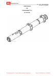
890GTR
Battery Inverter
HA502996 Issue 1
Product Manual
aerospace
climate control
electromechanical
filtration
fluid & gas handling
hydraulics
pneumatics
process control
sealing & shielding
ENGINEERING YOUR SUCCESS.
890GTR Inverter Product Manual
HA502996 Issue 01
Software Version: 5.3
WARRANTY The general terms and conditions of sale of goods and/or services of Parker Hannifin Europe Sárl, Luxembourg,
Switzerland Branch, Etoy, apply to this product unless otherwise agreed. The terms and conditions are available on our website
www.parker.com/termsandconditions/switzerland
Parker EGT reserves the right to change the content and product specification without notice.
2015 Parker EGT, a division of Parker Hannifin Corporation
All rights strictly reserved. No part of this document may be stored in a retrieval system, or transmitted in any form or by any means
to persons not employed by a Parker EGT company without written permission from Parker EGT, a division of Parker Hannifin
Corporation. Although every effort has been taken to ensure the accuracy of this document, it may be necessary, without notice, to
make amendments or correct omissions. Parker EGT cannot accept responsibility for damage, injury, or expenses resulting
therefrom.
IMPROPER SELECTION OR IMPROPER USE OF THE PRODUCTS DESCRIBED HEREIN OR RELATED ITEMS CAN CAUSE
DEATH, PERSONAL INJURY AND PROPERTY DAMAGE.
This document and other information from Parker-Hannifin Corporation, its subsidiaries and authorized distributors provide product or
system options for further investigation by users having technical expertise.
The user, through its own analysis and testing, is solely responsible for making the final selection of the system and components and
assuring that all performance, endurance, maintenance, safety and warning requirements of the application are met. The user must
analyze all aspects of the application, follow applicable industry standards, and follow the information concerning the product in the
current product catalogue and in any other materials provided from Parker Hannifin Corporation or its subsidiaries or authorized
distributors.
To the extent that Parker Hannifin Corporation or its subsidiaries or authorized distributors provide component or system options
based upon data or specifications provided by the user, the user is responsible for determining that such data and specifications are
suitable and sufficient for all applications and reasonably foreseeable uses of the components or systems.
The above disclaimer is being specifically brought to the user’s attention and is in addition to and not in substitution to the Exclusions
and Limitations on Liability which are set out in the terms and conditions of sale.
Table of Contents
890GTR INVERTER PRODUCT MANUAL ..........................................................................................................................................................................1-1
CHAPTER 1 SAFETY................................................................................................................................................................................................................1-1
Requirements................................................................................................................................................................................................................................................................................ 1-3
Product Warnings and Symbols ................................................................................................................................................................................................................................................... 1-4
Hazards......................................................................................................................................................................................................................................................................................... 1-5
Safety ........................................................................................................................................................................................................................................................................................... 1-6
Application Risks ......................................................................................................................................................................................................................................................................... 1-7
Parker Required Personal Protection Equipment (PPE) ............................................................................................................................................................................................................... 1-9
CHAPTER 2 GETTING STARTED .........................................................................................................................................................................................2-1
Abbreviations / Definitions .......................................................................................................................................................................................................................................................... 2-3
Product Overview......................................................................................................................................................................................................................................................................... 2-4
Getting Started ............................................................................................................................................................................................................................................................................. 2-5
CHAPTER 3 INSTALLATION .................................................................................................................................................................................................3-1
Mechanical Installation ................................................................................................................................................................................................................................................................ 3-2
Layout Diagram ...................................................................................................................................................................................................................................................................... 3-5
Dimensions ............................................................................................................................................................................................................................................................................. 3-6
Air Flow & Ventilation Requirements .................................................................................................................................................................................................................................... 3-7
Lifting Instructions ................................................................................................................................................................................................................................................................. 3-8
Electrical Installation.................................................................................................................................................................................................................................................................. 3-11
Wiring Requirements ............................................................................................................................................................................................................................................................ 3-13
Functional Overview / Block Diagram....................................................................................................................................................................................................................................... 3-17
Start-up Sequence ....................................................................................................................................................................................................................................................................... 3-18
CHAPTER 4 OPERATIONS .....................................................................................................................................................................................................4-1
Utility Interconnection and Grid Fault Interface .......................................................................................................................................................................................................................... 4-2
Normal Grid Operation ........................................................................................................................................................................................................................................................... 4-2
890GTR Inverter Power Manual HA502996
Voltage Ride Through Behaviour ........................................................................................................................................................................................................................................... 4-2
Frequency Ride through Behaviour ........................................................................................................................................................................................................................................ 4-3
Anti-Islanding Behaviour ....................................................................................................................................................................................................................................................... 4-4
Modbus Register Maps ........................................................................................................................................................................................................................................................... 4-4
Emergency Power Off (EPO) ....................................................................................................................................................................................................................................................... 4-8
80 KW String Inverter ............................................................................................................................................................................................................................................................ 4-8
CHAPTER 5 TRIPS & FAULT FINDING ..............................................................................................................................................................................5-1
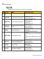
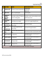
Trips ............................................................................................................................................................................................................................................................................................. 5-2
What Happens when a Trip Occurs ........................................................................................................................................................................................................................................ 5-2
Resetting a Trip Condition...................................................................................................................................................................................................................................................... 5-3
Trips Table.............................................................................................................................................................................................................................................................................. 5-4
Checksum Fail ........................................................................................................................................................................................................................................................................ 5-6
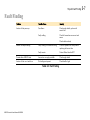
Fault Finding ................................................................................................................................................................................................................................................................................ 5-7
CHAPTER 6 ROUTINE MAINTENANCE & REPAIR ........................................................................................................................................................6-1
Cleaning Instructions.................................................................................................................................................................................................................................................................... 6-3
Fan Maintenance & Replacement ................................................................................................................................................................................................................................................ 6-4
Reactive Maintenance ............................................................................................................................................................................................................................................................. 6-4
Preventative Maintenance ....................................................................................................................................................................................................................................................... 6-4
Auxiliary Power Output Fuse Replacement ................................................................................................................................................................................................................................. 6-7
CHAPTER 7 PPE ........................................................................................................................................................................................................................7-1
OSHA PPE REGULATIONS: ..................................................................................................................................................................................................................................................... 7-3
Guidelines .................................................................................................................................................................................................................................................................................... 7-3
General Requirements ............................................................................................................................................................................................................................................................ 7-3
Training Requirements ................................................................................................................................................................................................................................................................. 7-4
Protection Requirements .............................................................................................................................................................................................................................................................. 7-4
Head, Foot, and Hand Protection ............................................................................................................................................................................................................................................ 7-4
Eye and Face Protection ......................................................................................................................................................................................................................................................... 7-5
Hearing Protection .................................................................................................................................................................................................................................................................. 7-5
Posting Requirements ............................................................................................................................................................................................................................................................. 7-6
OSHA Personal Protective Equipment Policy & Procedure (1910.0132- .0136)......................................................................................................................................................................... 7-7
Personal Protective Equipment Inspection ................................................................................................................................................................................................................................... 7-8
890GTR Inverter Power Manual HA502996
CHAPTER 8 ETHERNET .........................................................................................................................................................................................................8-1
Objective ...................................................................................................................................................................................................................................................................................... 8-2
Procedure ................................................................................................................................................................................................................................................................................ 8-2
Hardcoded Option (for 890 hardware) .................................................................................................................................................................................................................................... 8-3
APPENDIX A INVERTER KEYPAD ......................................................................................................................................................................................... 1
APPENDIX B PROGRAMMING................................................................................................................................................................................................ 1
Configure the Inverter ......................................................................................................................................................................................................................................................................2
Configure the Inverter.................................................................................................................................................................................................................................................................2
Connecting to a PC .....................................................................................................................................................................................................................................................................2
Programming with Block Diagrams ...........................................................................................................................................................................................................................................2
APPENDIX C COMPLIANCE .................................................................................................................................................................................................... 1
Introduction ......................................................................................................................................................................................................................................................................................2
European Compliance ......................................................................................................................................................................................................................................................................3
CE Marking ................................................................................................................................................................................................................................................................................3
EMC Compliance .......................................................................................................................................................................................................................................................................4
Australia & New Zealand .................................................................................................................................................................................................................................................................6
EMC Standards ...........................................................................................................................................................................................................................................................................6
EMC .................................................................................................................................................................................................................................................................................................7
Emissions Limits ........................................................................................................................................................................................................................................................................7
EMC General Installation Considerations ...................................................................................................................................................................................................................................... 12
Earthing Requirements ............................................................................................................................................................................................................................................................. 12
APPENDIX D ASSOCIATED EQUIPMENT ............................................................................................................................................................................ 1
APPENDIX E TECHNICAL SPECIFICATIONS ..................................................................................................................................................................... 1
DSE Lite Configuration Tool ...........................................................................................................................................................................................................................................................2
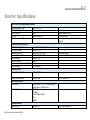
Inverter Specifications......................................................................................................................................................................................................................................................................3
Understanding the Product Code ......................................................................................................................................................................................................................................................5
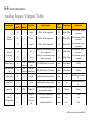
Analog Input / Output Table ............................................................................................................................................................................................................................................................6
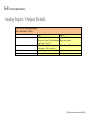
Analog Input / Output Details ..........................................................................................................................................................................................................................................................8
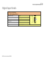
Digital Input Details .........................................................................................................................................................................................................................................................................9
890GTR Inverter Power Manual HA502996
Digital Output Details .................................................................................................................................................................................................................................................................... 10
User 24V Output Details ................................................................................................................................................................................................................................................................ 11
Earthing/Safety Details .................................................................................................................................................................................................................................................................. 12
Grid Responses ............................................................................................................................................................................................................................................................................... 13
HVRT and LVRT ..................................................................................................................................................................................................................................................................... 13
Changing Voltage and Frequency Fault Trip Levels and Times ....................................................................................................................................................................................................15
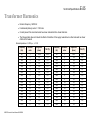
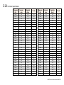
Transformer Harmonics ................................................................................................................................................................................................................................................................. 25
Connector Torque Requirements .............................................................................................................................................................................................................................................. 28
APPENDIX F LIST OF FAULT CODES ................................................................................................................................................................................... 1
890GTR Inverter Power Manual HA502996
Safety
Safety Information
Chapter 1
Safety
Please read these important Safety notes before performing maintenance or operating this equipment.
CAUTION
WARNING
CAUTION notes in the manual warn of danger
To equipment
WARNING notes in the manual warn of danger to personnel
This section contains the following parts:
•
Requirements
•
Product Warnings and Symbols
•
Hazards
•
Safety
•
Application Risks
•
Parker Required Personal Protection Equipment (PPE)
890GTR Inverter Power Manual HA502996
1-1
1-2 Safety
Safety Information
IMPORTANT SAFETY INSTRUCTIONS
SAVE THESE INSTRUCTIONS
This manual contains important instructions for all 890GTR models that shall be followed during
installation and maintenance of the inverter.
890GTR Inverter Power Manual HA502996
Safety
1-3
Safety Information
Requirements
IMPORTANT
Please read this information BEFORE installing the equipment.
Intended Users
This manual is to be made available to all persons who are required to configure or service equipment described herein, or any other
associated operation.
The information given is intended to highlight safety issues, and to enable the user to obtain maximum benefit from the equipment.
Application Area
The equipment described is intended for use as power conversion in an energy storage system.
Personnel
Installation, operation and maintenance of the equipment should be carried out by qualified personnel. A qualified person is
someone who is technically competent and familiar with all safety information and established safety practices; with the installation
process, operation and maintenance of this equipment; and with all the hazards involved.
Training
Qualified personnel must be trained in Safety-Related Work Practices, Job Hazard Analysis, First Aid and CPR, Arc Flash Hazards,
and PPE Requirements (both classroom and on-the-job training are required in accordance with NFPA 70E requirements).
Retraining is required in intervals not to exceed three years.
890GTR Inverter Power Manual HA502996
1-4 Safety
Safety Information
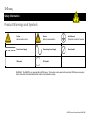
Product Warnings and Symbols
Caution
Risk of electric shock
Caution
Refer to documentation
Earth/Ground
Protective Conductor Terminal
Direct Current Supply
Alternating Current Supply
Phase Symbol
ON Symbol
OFF Symbol
WARNING: The 890GTR is not provided with a GFDI device. This inverter must be used with an external GFDI device as required
by the Article 690 of the National Electrical Code for the Installation location.
890GTR Inverter Power Manual HA502996
Safety
1-5
Safety Information
Hazards
DANGER! – Ignoring the following may result in injury
1.
This equipment can endanger life by exposure to high
voltages.
2.
The equipment must be permanently earthed due to the high
earth leakage current, and the supplies and loads must be
connected to an appropriate safety earth.
3.
Ensure all incoming supplies are isolated before working on
the equipment. Be aware that there may be more than one
supply connection to the inverter.
4.
There may still be dangerous voltages present at power
terminals (battery inputs and DC bus) when the inverter is
stopped.
890GTR Inverter Power Manual HA502996
5.
For measurements use only a meter to IEC 61010 (CAT III or
higher). Always begin using the highest range. CAT I and CAT II
meters must not be used on this product.
6.
Under normal circumstances the AC and DC Bus should
discharge within 10 minutes. Use a meter capable of measuring
up to 1000 VDC & 600 VAC RMS to confirm that less than 50V is
present on the DC BUS and between all power terminals and
earth before working on or near the DC Bus.
7.
Unless otherwise stated, this product must NOT be dismantled. In
the event of a fault the component must be returned.
1-6 Safety
Safety Information
WARNING! – Ignoring the following may result in injury or damage to equipment
Safety
Where there is conflict between EMC and Safety requirements, personnel safety shall always take precedence.
•
Never perform high voltage resistance checks on the wiring
without first disconnecting the inverter from the circuit being
tested.
•
All control and signal terminals are SELV; that is, protected
by double insulation. Ensure all external wiring is rated for
the highest system voltage.
•
Whilst ensuring ventilation is sufficient, provide guarding and
/or additional safety systems to prevent injury or damage to
equipment.
•
All exposed metalwork in the inverter is protected by basic
insulation and bonded to a safety earth.
•
Residual-current devices (RCDs) are not recommended for
use with this product; but where their use is mandatory, only
Type B RCDs should be used.
•
This is a product of the restricted sales distribution class
according to IEC 61800-3. It is designated as “professional
equipment” as defined in EN61000-3-2. Permission of the
supply authority shall be obtained before connection to the
low voltage supply.
•
When replacing a component in an application and before
returning to use, it is essential that all user defined
parameters for the product’s operation are correctly installed.
EMC
•
In a domestic environment this product may cause radio
interference in which case supplementary mitigation
measures may be required.
•
This equipment contains electrostatic discharge (ESD)
sensitive parts. Observe static control precautions when
handling, installing and servicing this product.
890GTR Inverter Power Manual HA502996
Safety
Safety Information
CAUTION!
Application Risks
•
The specifications, processes and circuitry described herein are for guidance only and may need to be adapted to the user’s
specific application. We cannot guarantee the suitability of the equipment described in this Manual for individual applications.
Risk Assessment
Under fault conditions, power loss or unintended operating conditions, the inverter may not operate as intended. In particular:
Stored energy might not discharge to safe levels as quickly as suggested and can still be present even though the inverter appears to be
switched off.
An inverter is a component within a system that may influence its operation or effects under a fault condition. Consideration must be given to:
•
Stored energy
890GTR Inverter Power Manual HA502996
•
Supply disconnects
•
Sequencing logic
•
Unintended operation
1-7
1-8 Safety
Safety Information
WARNING! – Ignoring the following may result in serious injury or damage to equipment
OSHA Electric Power Generation, transmission, and distribution safety standards (29 CFR 1910.269) consideration:
Workers may be exposed to arc flash hazards, electric shocks, and burns that can cause injury and death when making battery or
grid connections. Do not work on connections to the battery container or the grid without proper safety considerations.
Safe work practices as proscribed in OSHA’s Electric Power Generation, Transmission and Distribution Standard must be
implemented and observed. Workers must complete worker training requirements of OSHA’s Electric Power Generation,
Transmission and Distribution Standard, 29 CFR 1910.269.
Dangerous electrical potentials which can result in electrocution and arc flash hazards are present while the battery container is
connected. Workers must pay attention to both battery power conductors and overhead power lines. While fatal electrocution is the
main hazard, other hazards include using tools and equipment that can contact power lines.
• Look for overhead power lines and buried power line indicators.
• Stay at least 10 feet away from overhead power lines and assume they are energized.
• De-energize and ground lines when working near them.
• Use non-conductive wood or fiberglass ladders when working near power lines.
890GTR Inverter Power Manual HA502996
Safety
1-9
Safety Information
WARNING! – Ignoring the following may result in serious injury or damage to equipment
Parker Required Personal Protection Equipment (PPE)
The following list is the minimum PPE requirements in accordance with NFPA 70E Article 130.7. When working within the Restricted
Approach Boundary, the worker shall wear PPE in accordance with Article 130.4. When working within the Arc Flash Boundary, the worker
shall wear PPE in accordance with Article 130.5. All parts of the body inside the Arc Flash Boundary shall be protected. Any person who
will be required to use PPE will be required to complete training on the proper use of PPE. NFPA 70E Article 320.3(2) prohibits the wear of
conductive objects and jewellery.
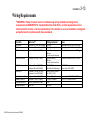
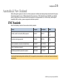
Table 1-1 Required PPE Optimum Specifications for HRC2 (8 cal/cm2)
ITEM
Hard Hat
Face Shield
Safety Glasses
RATING
Type 1, Class E
10 cal/cm2
ANSI Z87.1-2010
Balaclava
10.5 cal/cm2
Hearing Protection
22 dB (A)
Undergarments
Natural Fibers
Shirt*
Pants**
10.5 cal/cm2
10.5 cal/cm2
Coveralls***
12.2 cal/cm2
Rubber Insulating Gloves
Class 0
890GTR Inverter Power Manual HA502996
NOTE
Must be nonconductive – ANSI/ISEA Z89.1-2009
ASTM F 2178-08
Must be rated for Arc Flash
When working within the Restricted Approach Boundary or the Arc Flash Boundary
- ASTM F 1506-10a
Must be Ear Canal Inserts - OSHA 1910.95
Meltable fibers such as acetate, nylon, polyester, polypropylene and spandex are not
permitted
Daily wear - ASTM F 1506-10a
Daily wear - ASTM F 1506-10a
When working within the Restricted Approach Boundary or the Arc Flash Boundary
- ASTM F 1506-10a
When Insulated Gloves are required by task - ASTM D 120-09
1-10 Safety
Safety Information
ITEM
RATING
NOTE
When Insulated Gloves are required by task (Minimum thickness .03in, unlined,
Leather Protectors
ASTM F 496-06
ATPV value > 10 cal/cm2)
Cotton Liners
Cotton
When Insulated Gloves are required by task (optional)
Steel Toe Boots
Heavy-duty Leather
Daily wear - ASTF 2413-05 (must be non-conductive) NO ESD
Garments worn as outer layers over arc-rated clothing must also be made from arcOuter Layers
rated material (Use as Required)
Tools
1000V-Rated
When work on live circuits (>50V) is required by task - ASTM F 1505
*If a shirt is worn as a top layer, it must be rated at 10.5 cal/cm2. If it is worn under coveralls rated at 12.2 cal/cm2, it may be natural fibers and
may be short-sleeved.
**If pants are worn as a top layer, they must be rated at 10.5 cal/cm2. If they are worn under coveralls rated at 12.2 cal/cm2, they may be
natural fibers.
***Coveralls are the preferred method of protection.
For more information please see Chapter 7 PPE
890GTR Inverter Power Manual HA502996
Safety
1-11
Safety Information
WARNING! – Ignoring the following may result in serious injury or damage to equipment Limited Approach Boundary, Restricted
Approach Boundary, Prohibited Approach Boundary
Approach Boundaries to Exposed energized Conductors/Parts for qualified employees (NFPA 70E Table 12-1):
•
For troubleshooting and testing purposes only, qualified persons using proper test equipment and personal protective equipment
must adhere to the boundaries shown below. For adjusting, tightening, calibrating or other work, the circuits must be de-energized,
or employees must use voltage-rated gloves and voltage-rated insulated tools.
•
For Low Voltage Troubleshooting and Testing only (under 480 volts), a qualified person may penetrate the prohibited approach
boundary with instrument probes, leads, CT’s, etc. The qualified person must wear Class 00 (500 volt-rated) gloves.
•
Supervisors and employees must ensure that an unqualified person can never come closer to any energized line or part than the
Limited Approach Boundaries
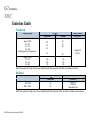
Table 1-2 Approach Boundaries by Voltage
< 50 VAC
50-300 VAC
301-750 VAC
< 100 VDC
100-300 VDC
301-1k VDC
Limited Approach
Not
10’ – 0”
10’ – 0”
(Exposed movable conductors)
Specified
Limited Approach
Not
3’ – 6”
3’ – 6”
(Exposed fixed circuit parts)
Specified
Restricted Approach
Not
Avoid Contact
1’ – 0”
(Shock protection Required + PPE)
Specified
Prohibited Approach
Not
Avoid Contact
0’ – 1”
(Equivalent to direct contact)
Specified
1
Boundary indicates the minimum working distance of the worker’s face and chest
Approach Boundary1,2
2
Limited Approach Boundary is 0” with all Access Doors and Panels closed and secured.
890GTR Inverter Power Manual HA502996
1.1-5 kVDC
751-15 kVAC
5-15 kVDC
10’ – 0”
10’ – 0”
5’ – 0”
5’ – 0”
1’ – 5”
2’ – 2”
0’ – 4”
0’ – 7”
1-12 Safety
Safety Information
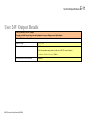
WARNING
ARC FLASH AND SHOCK HAZARD
This unit is powered by batteries
Do not work on this equipment
Without locking out all battery sources
Figure 1-1 Battery Inverter Warning Placard
A variety of battery types may be used in battery enclosures to supply a DC input to the Battery Inverter Enclosure. Each manufacturer can
provide specific Cautions and Warnings for work on and around batteries and for battery storage which should be observed.
890GTR Inverter Power Manual HA502996
Getting Started
Chapter 2
Getting Started
A few things you should know about this manual.
•
How the Manual is organized
•
Initial Steps
•
Abbreviations / Definitions
890GTR Inverter Power Manual HA502996
2-1
2-2 Getting Started
About this Manual
This manual is intended for use by service and maintenance personnel. It assumes reasonable levels of understanding in the
disciplines required to service and maintain this equipment.
Note
Please read all Safety information before proceeding with the service, maintenance and operation of this unit.
It is important that you pass this manual on to any new user of this unit.
How the Manual is organized
This manual is organized into chapters, indicated by the numbering on the edge of each page.
The manual is focused on servicing and maintaining the Inverter Enclosure. For more detailed information on specific components
inside the inverter, refer to the relevant manufacturer’s product manual.
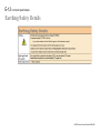
Initial Steps
Use the manual to help you plan the following:
Service and Maintenance
Know your requirements:
Training requirements
OSHA Safety conformance
Compliance with Arc Flash requirements
Contact Details
Parker Hannifin Corporation, Automation Group, Energy Grid Tie Division, 9201 Forsyth Park Drive, Charlotte, NC28273, USA.
Tel: +1 704 5874051
www.parker.com/egt
890GTR Inverter Power Manual HA502996
Getting Started
2-3
Abbreviations / Definitions
AC
Alternating Current
LVRT
Low Voltage Ride Through
ANSI
American National Standards Institute
MPPT
Maximum Power Point Tracking
APT
Active Power Tracking
MPT
Maximum Power Tracking
AVR
Automatic Voltage Regulation
MVA
Mega-Volt Amperes (Apparent Power)
MW
Megawatts (Real Power)
PCM
Parallel Control Module
Converter A device that converts one type of energy to
another (AC-AC, AC-DC, DC-DC, or DC-AC)
DC
Direct Current
PCS
Power Conversion Station (Inverter Transformer Pad)
Drive
a generic term for an Adjustable Speed Drive
(ASD) or Variable Speed Drive (VSD)
PF
Power Factor
Plant
Power Plant
EPO
Emergency Power Off
PLC
Programmable Logic Controller
FR
Flame Resistant
PPC
Power Plant Controller
HRC
Hazard Risk Category
PPE
Personal Protection Equipment
HVRT
High Voltage Ride Through
P/S
Power Supply
HMI
Human Machine Interface
PV
Photovoltaic
HOL
High Operating Limit
RPI
Requested Packet Interval
IGBT
Insulated Gate Bipolar Transistor
SCADA
Supervisory Control and Data Acquisition
Inverter
A converter that changes DC current into AC
current
SP
Setpoint
System
Power Plant Control System
LOL
Low Operating Limit
VAR
Volt Ampere Reactive (Reactive Power)
LOTO
Lock Out Tag Out
XML
Extensible Markup Language
890GTR Inverter Power Manual HA502996
2-4 Getting Started
Product Overview
Control Features
The inverter is fully a featured grid/battery interface when controlled using the Modbus TCP interface. Customized programming can
be accomplished via either the local USB or LAN interface.
General
Protection
Inputs/Outputs
Output Frequency
Switching Frequency
Nominal 50 or 60 Hz with adjustable trip points.
Minimum 2kHz.
Nominal 4kHz (optimal for output filter)
Maximum 5kHz.
Control Modes
Real (Id) and reactive (Iq) current control
Power (KW) and VAR (KVAR) control
Support functions
Frequency support
Low Voltage Ride through with KVAR injection
Diagnostics
Full diagnostic and monitoring facilities
Trip Conditions
Output short line to line
Overcurrent > 220% HD current
Heat sink over temperature
Filter inductor over temperature
DC bus overvoltage and under voltage
AC grid overvoltage
AC grid under voltage and LVRT
AC grid over frequency and under frequency
Current Limit
IxT foldback
Heat sink temperature foldback
Rating
100% continuous (128 Arms)
150% for 60 seconds (192 Arms)
Analog Inputs
Digital Inputs
2 configurable inputs; voltage or current
3 configurable 24V dc inputs
890GTR Inverter Power Manual HA502996
Getting Started
2-5
Getting Started
References:
DSE Lite Configuration Tool Software Manual—HA471486U001
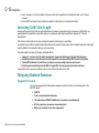
Overview:
The 890GTR is based on the AC890 control platform utilizing the DSE (Drive System Explorer) Configuration Tool. DSE Lite is
software that can be loaded onto a compatible PC. The PC can then be connected to the 890GTR via a micro-USB cable. Once
connected, the PC provides a portal into the 890GTR allowing monitoring and control of critical variables and modification to the
application layer of the inverter. The application layer, known as the “Configuration”, allows customization of the 890GTR’s
programming using a graphical block diagram language.
Firmware, not to be confused with the configuration, contains operating system of the 890GTR. Firmware cannot be modified by the
user, but may need to be updated from time to time to accommodate enhancements. The 890GTR uses Version 5 firmware which
has been optimized for grid ties applications.
Connecting with DSE Lite:
1. Load DSE Lite onto compatible PC (refer to DSE Lite manual).
2. Connect computer to 890GTR using mini-USB communication cable.
3. Launch DSE Lite.
4. Ensure 890GTR has control power present.
5. Establish connection to 890GTR by clicking refresh (refer to DSE Lite manual).
890GTR Inverter Power Manual HA502996
2-6 Getting Started
Creating a configuration
A configuration can be created using DSE Lite. Several templates are available to jump start the process and templates are model
and firmware specific. Simply click on “FileNew890Ver5v5x_DFLT.890” to load the appropriate template. The template will
appear as a tab in DSE Lite. Once the configuration has been created it can be saved under a new name using the “save copy as”
under the File menu.
890GTR Inverter Power Manual HA502996
Getting Started
2-7
Modifying a configuration:
When configuration is open in DSE Lite, modifications can be made using the DSE Lite editor. Refer to DSE Lite manual for details.
Loading a configuration:
When a configuration is ready it should be saved to disk before downloading to the inverter. Below are the basic steps to load a
configuration into the inverter:
1. Save configuration to disk (FileSave).
2. Ensure inverter is not running (synchronized to grid).
3. Ensure DSE Lite is connected and communicating to inverter (CommandRefresh Partial).
4. Install configuration to inverter (CommandInstall)
Setting IP address (see Chapter 8 for additional details)
Method 1 (Manual):
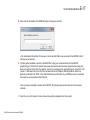
1. Connect using DSE Lite.
2. Load Configuration into DSE Lite editor either by “Extracting” configuration from inverter or by loading a configuration file.
3. Navigate to page 5 of configuration where “Ethernet block” is located.
4. Double click on “Ethernet block” to open dialog/parameter box.
5. Enter in correct IP address.
6. Save updated configuration to disk if desired.
7. Install updated configuration into inverter.
Method 2 (BOOT P):
1. When an installed configuration has an IP address set to 0.0.0.0, then the inverter will request an IP address from the
Ethernet server.
2. Refer to DSE Lite manual for details.
890GTR Inverter Power Manual HA502996
2-8 Getting Started
Updating firmware
Occasionally it may be necessary to update the 890GTR firmware to enable new functions or address specific requirements. This
can also be done through DSE Lite using the following procedure:
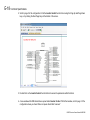
1. Copy new firmware file into the following directory on a computer loaded with DSE Lite configuration tool:
C:\SSD_link\firmware\
2. Connect to inverter using DSE Lite.
3. Ensure inverter is not running.
4. Click on: CommandInstall Firmware
5. Confirm Install Firmware by clicking on message box.
6. Select firmware using drop down list.
7. Begin firmware load by clicking on “Install”.
890GTR Inverter Power Manual HA502996
Installation
Chapter 3
Installation
This chapter describes the mechanical and electrical installation of the 890GTR. Follow the steps for a successful installation.
•
Mechanical Installation
•
Lifting Instructions
•
Electrical Installation
•
Start-up Sequence
890GTR Inverter Power Manual HA502996
3-1
3-2 Installation
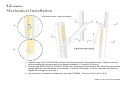
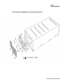
Mechanical Installation
U30 location shown. Adjust accordingly.
1:
2:
1. Install the cage nuts (FZ474257U006) into the outer side faces of the vertical rails as shown. Snap the nuts into
the third opening up from the bottom of the desired installation “U” location (U30 shown).
2. Hang the rails (BX474176U001 & BX474176U002) onto the side faces of the vertical rails. Slide the hooks into the
second opening up from the bottom of the desired “U” location (U30 shown). Push the rails down until the slot is
aligned with the cage nut from step 1.
3. Use a pozidrive 3 screwdriver to fasten the rails using FY388805. Torque to 6-7 Nm (4.4-5.2 lb-ft).
890GTR Inverter Power Manual HA502996 Installation
3-3
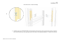
U30 location shown. Adjust accordingly.
4:
4. Install the cage nuts (FZ474257U006) into the backside of the front face of the vertical rails as shown. Snap the
nuts into the seventh and ninth openings up from the bottom of the desired installation “U” location (U30 shown).
890GTR Inverter Power Manual HA502996 3-4 Installation
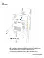
5. Install the 890GTR onto the rails and slide back into place until the front face comes in contact with the vertical
rails. Caution: product has mass of 91 kg (200 lbs), see 3-7 for proper lifting instructions.
6. Use a pozidrive 3 screwdriver to fasten the 890GTR using FY388805. Torque to 6-7 Nm (4.4-5.2 lb-ft).
890GTR Inverter Power Manual HA502996
Installation
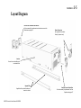
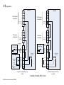
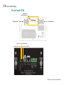
Layout Diagram
Exhaust Fan Assemblies with Guards
Can be removed for replacement and maintenance see Fan
Maintenance page 6-4
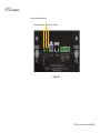
Power Connectors
Not supplied with product.
View for reference only
Inverter
No end-user serviceable parts
contained within
Support Rails
Supplied with required hardware to
mount in cabinet
890GTR Inverter Power Manual HA502996
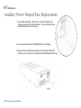
Auxiliary Power Output Fuse
Can be removed for replacement see Fuse
Replacement page 6-7
3-5
3-6 Installation
Dimensions
All dimensions are in mm.
444
210
215
35
1054
483
890GTR Inverter Power Manual HA502996
Installation
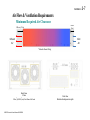
Air Flow & Ventilation Requirements
Minimum Required Air Clearance
75 mm*
(3 in)
200 mm (7.9 in)
Exhaust
Air
Inlet
Air
*Excludes Power Wiring
Back View
3 Fans
3
3
510 m /h (300 ft /min) Total Flow at Full Load
890GTR Inverter Power Manual HA502996
Front View
Minimize blockage across grills
3-7
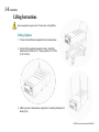
3-8 Installation
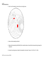
Lifting Instructions
Ensure equipment is properly rated. Product mass: 91kg (200lbm).
Lifting Options
1. Product can be lifted and supported from the base surface.
2. Can be lifted by eyebolts screwed into sides. See lifting
dimensions for details (3-10). Torque eyebolts to 16-17 Nm
(11.8-12.5 lb-ft).
3. Lifted by cutouts in base surface using hooks. See lifting dimensions for
details (3-10).
890GTR Inverter Power Manual HA502996
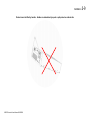
Installation
Product cannot be lifted by handles. Handles are intended only to push or pull product on cabinet rails.
890GTR Inverter Power Manual HA502996
3-9
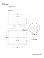
3-10 Installation
Lifting Dimensions
All dimensions in mm.
BOTTOM
890GTR Inverter Power Manual HA502996
Installation
3-11
Electrical Installation
IMPORTANT
Please read the Safety Information on in Chapter 1 before proceeding.
HVIL (High Voltage Interrupt Loop) & Emergency Stop
AMP Mini Mate-N-Lok, 6 way, Female
DC Power Connector
Amphenol Powerlok,
300 Series,
2 Position with X Polarization
Status Lights
See following figure
I/O
RJ45 Ethernet Socket
For communicating with
inverter over Modbus TCP
Discrete I/O
Phoenix Base Strip MC1,5/9-g-3,81
Additional Analog &
AC Power Connector
Digital Signals.
Amphenol Powerlok,
See Figure 3-2
300 Series,
3 Position with X Polarization
{
DC Ready Status Light
AC Ready Status Light
+ Auxiliary Power Out
IEC Appliance Outlet C13
120VAC 50/60Hz
Control Power In
IEC Appliance Inlet C14
120VAC 50/60Hz. To be
supplied by end-user.
Ground Studs
M6x1
Programming Port
Mini-USB
For installing configuration
software into the inverter
Figure 3-1 Layout Diagram
890GTR Inverter Power Manual HA502996
Auxiliary Power Output Fuse
Type ABC
3-12 Installation
Inverter is Synchronized to Grid
Control Power Exists
Inverter has Tripped
Figure 3-2
890GTR Inverter Power Manual HA502996
Installation
3-13
Wiring Requirements
**WARNING: Parker Inverters must be installed using wiring methods according to the
requirements of ANSI/NFPA 70, Canadian Electrical Code Part I, or other appropriate local or
national electrical codes. It is the responsibility of the installer to ensure installation is designed
and performed in compliance with these standards.
Function
DC Ground
AC Ground
DC Bus Connection
Wire size**
2
Minimum 21.2 mm wire (4 AWG)
Minimum 13.3 mm2 wire (6 AWG)
Minimum 33.6 mm2 (2 AWG)
AC Bus Connection
Minimum 33.6 mm2 (2 AWG)
HVIL & Emergency Stop
Minimum 0.3 mm2 (22 AWG)
Maximum 0.8 mm2 (18 AWG)
Minimum 0.14 mm2 (28 AWG)
Maximum 1.5 mm2 (16 AWG)
Minimum 2.1 mm2 (14 AWG)
Minimum 2.1 mm2 (14 AWG)
Cat5 w Shield Ethernet Cable
Mini-USB
Discrete I/O
Auxiliary Power Out
Auxiliary Power In
Communication Port
Programming Port
890GTR Inverter Power Manual HA502996
Mating Connector
Wire Lug
Wire Lug
Amphenol Powerlok,
300 Series,
2 Position with X Polarization
Amphenol Powerlok,
300 Series,
3 Position with X Polarization
AMP 172168-1
(Mini Mate-N-Lok Housing)
Phoenix Contact 1803646
(MC 1,5/9-ST-3,81)
IEC type C14 (male)
IEC type C13 (female)
RJ-45
Mini-USB
Notes
Tightening torque 6-7 Nm (4.4-5.2 lb-ft)
Tightening torque 6-7 Nm (4.4-5.2 lb-ft)
Maximum continuous current = 160ADC
Maximum continuous current = 128ARMS
AMP 770988-1
(crimp socket, 18-22 AWG)
Rated output = 120V, 750VA, 50/60Hz
120V (+/-5%), 150VA, 50/60Hz
3-14 Installation
DC connection notes:
1. Verify correct polarity before connecting to the DC bus. Improper DC polarity could result in damage to the inverter
and/or DC supply.
2. DC supply must provide a method to pre-charge the DC bus capacitors contained within the inverter. Failure to
properly pre-charge the inverter will result in high inrush currents possibly damaging the inverter.
3. External fusing or breaker is required for the DC connection.
4. Lethal voltages and energies are present in this equipment. It is the responsibility of the installer to follow the
requirements of ANSI/NFPA 70, Canadian Electrical Code Part I, and/or other appropriate local and national
electrical codes.
5. It is the responsibility of the operator of this equipment to ensure adequate safety procedures and Arc Flash
precautions are followed.
AC connection notes:
1. AC polarity (phase rotation) is automatically detected and accommodated by the inverter.
2. AC supply must have appropriate disconnection and fusing. Refer to NEC and all applicable codes
3. Lethal voltages and energies are present in this equipment. It is the responsibility of the installer to follow the
requirements of ANSI/NFPA 70, Canadian Electrical Code Part I, and/or other appropriate local and national
electrical codes.
4. It is the responsibility of the operator of this equipment to ensure adequate safety procedures and Arc Flash
precautions are followed.
Estop/HVIL connection notes:
1. Although the Estop and HVIL circuits are galvanically isolated from the inverter control circuits, it is recommended
that they are referenced to ground potential.
2. Estop circuit requires external 24 Vdc but is polarity insensitive.
3. HVIL circuit utilizes isolated contacts in both AC and DC power connectors. External 24 Vdc power supply is
recommended. The following figure illustrates two possible connections schemes:
890GTR Inverter Power Manual HA502996
Installation
Inverter
Inverter
3P AC power
connection
3P AC power
connection
AC HVIL
jumper
DC power
connection
Estop &
Power Supply
AC HVIL
jumper
DC power
connection
DC HVIL
jumper
E-Stop/HVIL
connector
Estop &
Power Supply
DC HVIL
jumper
E-Stop/HVIL
connector
1
1
2
2
K2 Main AC
Pilot relay
BMS
BMS estop
Relay
+24 V
(BMS)
24 V Return
(BMS)
3
3
4
4
5
5
6
6
Proposed E-Stop & HVIL Circuit
w BMS
890GTR Inverter Power Manual HA502996
K2 Main AC
Pilot relay
Example E-Stop & HVIL Circuit
Proposed E-Stop & HVIL Circuit
w/o BMS
3-15
3-16 Installation
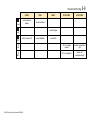
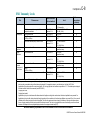
Auxiliary I/O connection notes:
Signal
Range
Description
Notes
AIN3
±10V, 0-10V,
0-20mA, 4-20mA
±10V, 0-10V,
0-20mA, 4-20mA
0-24 Vdc
0-24 Vdc
0-24 Vdc
Analog Input 3
(unassigned)
Analog Input 4
Available as special order (consult factory)
Digital Input 5
Digital Input 6
Digital Input 7
0V or open = False; +24V = True (unassigned)
0V or open = False; +24V = True (unassigned)
0V or open = False; +24V = True (unassigned)
AIN4
DIN5
DIN6
DIN7
890GTR Inverter Power Manual HA502996
Installation
3-17
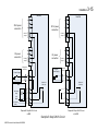
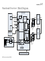
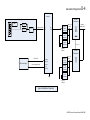
Functional Overview / Block Diagram
Limit
120 W
Ctrl Pwr
UPS Power 120 VAC
UPS Power
Supply
Grid Derivied 120 VAC
Uncomitted I/O
Comms
(Modbus TCP)
BMS
LAN
E-stop (in)
PCS OK
DC
Supply
Control Transformer
With OL protection
Fuse
Status
LEDs
3 Phase
Transformer
120 V
Breaker
Ctrl Pwr
E-Stop/HVIL
1. Estop
2. AC
connector
3. DC
connector
HVIL
BMS OK
Line Sync
Signal
USB
N x Transformers
Up to 85
Inverters
Filter Capacitor &
Damping Resistors
Breaker
Breaker
BMS
DC
Precharge
DC
Contactor
Fuse
(x3)
Current sensor
DC Bus
Connection
Fuse
DC Bus
Caps
Breaker
IGBTs
Current
Sensor
(x2)
Choke Assembly
Cooling Fans
String Inverter System Block Diagram
890GTR Inverter Power Manual HA502996
Medium
Voltage Grid
Breaker
3 Phase
Transformer
Line Sync
Attenuator
Power Board
Battery
400 VAC (3
phase)
Breaker
Controller
Optional Local User
Interface
(USB)
400 V
Fuse (x2)
AC contactor
Battery Rack
80 KW String Inverter
(product boundary)
Up to 85
Inverters
400 VAC (3 phase)
3-18 Installation
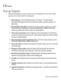
Start-up Sequence
Proper power up and starting sequence is required to successfully connect the DC supply with the Grid. Failure to follow an acceptable
sequence could result in damage to the inverter or associated equipment.
1.
Apply control power—connect 120 Volt 50/60 Hz ac power to “control power in”. This supply is typically an
Uninterruptable Power Supply (UPS) for black start and VRT features. Maximum control power requirements: 120
Watts (150 VA).
2.
Ensure Estop/EPO circuit is satisfied—an external 24 Volt DC supply is required to engage the main AC contactor.
This input is usually used in conjunction with a normally closed Estop pushbutton. Additionally, the High Voltage
Interrupt Loop contacts should be included in the Estop circuit. See Estop/EPO 3-14.
3.
Close dc bus pre-charge contactor—the DC bus capacitors need to be pre-charged through a current limited circuit
(i.e. resistor) to prevent excessively high in-rush currents. Failure to properly pre-charge the bus could result in damage
to the inverter or associated equipment.
4.
Ensure dc bus voltage is equal to DC supply voltage (+/-5%)—verify the dc bus is properly charged by query of the
DC LINK VOLTS parameter through the Modbus communication link.
5.
Close dc main contactor—once the DC bus is fully charged, then the main DC contactor can be closed. This contactor
is part of the DC supply.
6.
Disengage dc pre-charge contactor—opening the pre-charge contactor after closing the DC main contactor is
recommended to prevent damage to the pre-charge circuit in case the main contact opens unexpectedly.
7.
Ensure both start and stop bits are cleared—the Modbus Start Request and Stop Request parameters are rising
edge sensitive and it is good practice to initialize them before attempting a start.
8.
Clear faults—send a Fault Reset command to clear any extraneous faults that may have occurred during the startup
sequence.
9.
Verify faults are all cleared—read the Tripped bit to ensure all faults are cleared. Correct any persistent faults before
proceeding.
10. Toggle start bit true then false—the Start Request bit is rising edge sensitive. It is good practice to return the start bit
to false once a request is sent.
890GTR Inverter Power Manual HA502996
Installation
3-19
11. Wait 2 seconds—there are two 1 second delays built into the start up configuration. Therefore it may take at least two
seconds before the inverter actually starts and indicates a Running condition.
12. Verify inverter running—read the Running bit to make sure the inverter is enabled and connected to the grid.
13. Select Control Mode—select either Id/Iq or KW/KVAR control.
14. Set Output Demand—set either Id/Iq or KW/KVAR to desired level.
890GTR Inverter Power Manual HA502996
4-1 Operations
Chapter 4
Operations
•
Utility Interconnection and Grid Fault Interface
•
Normal Grid Operation
•
Voltage Ride Through Behaviour
•
Frequency Ride through Behaviour
•
Anti-Islanding Behaviour
•
Emergency Power Off (EPO)
890GTR Inverter Power Manual HA502996
Operations
4-2
Utility Interconnection and Grid Fault Interface
Normal Grid Operation
Energy is transmitted back and forth to the grid through power, reactive power, or power factor commands delivered to the inverter
via network communications or through discrete I/O. The 890GTR will attempt to meet the requested real power, reactive power or
power factor commands unless a system or device protection setting or algorithm prevents the inverter from achieving the desired
output. See table on page E-4 for environmental derating that may limit inverter output. In addition, parameters from the energy
storage supply like charge and discharge limits may override commanded system output. A full list of parameters can be found in
Appendix B.
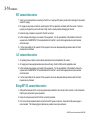
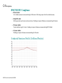
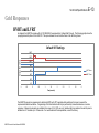
Voltage Ride Through Behaviour
A graph of pre-programmed and allowable voltage ride through settings can be found in Appendix E and in the Version 5 Firmware
manual. In the event of a grid voltage fault, the inverter will respond in the following manner:
Faults within the programmed trip time and voltage limits:
The inverter will respond in 1 of 3 ways.
1) Symmetric 3 phase fault with the “LVRT k” parameter in the Grid Control Function Block Menu set to 0: the inverter
will attempt to provide the pre-fault power and reactive power or power factor to within the current limits of the inverter.
In the event of excessive current required, the 890GTR will reduce reactive power and then real power to stay within
the current limits of the product.
2) Asymmetric fault: The inverter will remain synchronized to the grid but cease to export real power during the fault.
Reactive power from the internal capacitors will be present during the fault.
3) Symmetric 3 phase fault with the “LVRT k” parameter in the Grid Control Function Block Menu set to 1 or higher: the
inverter will output additional reactive current in proportion to the magnitude of the fault scaled by the “LVRT k”
parameter and use any remaining output current capacity to achieve the pre-fault power output setpoint. For example:
a product rated for 1000A output on a grid is outputting 300A of real power current and 100A of inductive reactive
current and has its LVRT k parameter set to 1. If the grid experienced a symmetric 3 phase fault causing its voltage to
drop down to 50% of its nominal value the inverter will: add 1*(50%*1000A)=500A of capacitive reactive current to its
890GTR Inverter Power Manual HA502996
4-3 Operations
per fault 100A output = 100A-500A = 400A of capacitive current. Power = Volts * Current so the drop in voltage of
50% requires the inverter to increase its real power current by 50% to maintain the same power output so its real
power current will go to 300A / 50% = 600A. Since real and reactive current components are added in quadrature the
inverter net output current will be SQRT( 400^2 + 600^2) = 721A. For another example: a product rated for 1000A
output on a grid is again outputting 300A of real power current and 100A of inductive reactive current and has its LVRT
k parameter set to 2. If the grid experienced a symmetric 3 phase fault causing its voltage to drop down to 50% of its
nominal value the inverter will: add 2*(50%*1000A)=1000A of capacitive reactive current to its per fault 100A output =
100A-1000A = 900A of capacitive current. Power = Volts * Current so the drop in voltage of 50% requires the inverter
to increase its real power current by 50% to maintain the same power output so its real power current would have to go
to 300A / 50% = 600A. In this case, since real and reactive current components are added in quadrature and reactive
current takes priority during a grid fault, the available inverter real power output current can only be be SQRT( 1000^2 900^2) = 435.9A so the inverter will output 900A of inductive reactive current and 435.9A of real power current for a
total of 1000A net current. The inverter will react the same way to high voltage faults with the exception that the
additional reactive current supplied during the fault will be inductive.
Faults outside the programmed trip time and voltage limits:
If a fault exceeds the programmed time duration with respect to the fault magnitude, or if the voltage exceeds the instantaneous
overvoltage trip levels, the inverter will transition to the Stop Fault state and indicate a VRT mains loss fault. The 890GTR will not
reconnect to the grid until after the grid has returned to within Range B of ANSI C84.1-1995, Table 1 and a frequency range of
59.3Hz to 60.5Hz if connected to a 60 Hz grid or 49.3Hz to 50.5Hz if connected to a 50Hz grid AND the grid has remained in this
range for the programmed time delay. See Appendix E (page no. E-15) and the Firmware Version 5 manual for the standard delay
and adjustable delay length ranges.
Frequency Ride through Behaviour
The inverter is capable of sustaining real and reactive power output in the event of grid frequency deviation. See Appendix E to see
the standard settings and upper and lower limits of operation. Standard as shipped 890GTRs do not have pre-programmed or
desired output change due to frequency deviation algorithms active. Consult Parker (page no. 2-2) for specific frequency ride
through behaviour requests.
890GTR Inverter Power Manual HA502996
Operations
4-4
Anti-Islanding Behaviour
WARNING: The 890GTR is shipped with anti-islanding capability disabled. It is the responsibility of the site operator to detect and
remove island conditions. Please consult Parker (page no. 2-2) to discuss turning the anti-island detection algorithm on.
In the event of an island condition, if the anti-islanding detection algorithm has been enabled by the factory, the 890GTR will detect
the formation of the island within 2 seconds of its creation. The inverter will transition to a Stop Fault state and cease the export of
power. The 890GTR will not reconnect to the grid until after the grid has returned to within Range B of ANSI C84.1-1995, Table 1
and a frequency range of 59.3Hz to 60.5Hz if connected to a 60 Hz grid or 49.3Hz to 50.5Hz if connected to a 50Hz grid AND the grid
has remained in this range for the programmed time delay. See Appendix E and the Firmware Version 5 manual for the standard
delay and adjustable delay length ranges.
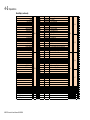
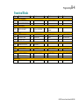
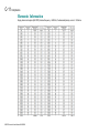
Modbus Register Maps
Read Map:
890GTR
Holding Reg.
Description
Address
DC Link Volts
257
Mains Current
259
Terminal Volts
261
Actual Current Limit
263
Heatsink Temperature (Hottest IGBT)
265
First Trip
267
Status Word 1
269
Type
Real
Real
Real
Real
Real
Dword
Dword
Condition Scale / Units
Volts DC
Amps AC (From Inv)
Volts AC (From Inv)
%
Degrees Celsius
Enumerated Value --->
Bitwise
Word
0 - 1
2 - 3
4 - 5
6 - 7
8 - 9
10 - 11
12 - 13
Byte
Bit
0 - 3 ~
4 - 7 ~
8 - 11 ~
12 - 15 ~
16 - 19 ~
20 - 23 ~
24 - 27 ~
890GTR Inverter Power Manual HA502996
4-5 Operations
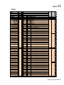
Read Map (continued):
Running
Tripped
Synchronized
Close Precharge
Current Control
Inverter Enabled
Hardware Sync
10M1 Status
Fan Failure
E-Stop Status
DIN5 Status
DIN6 Status
DIN7 Status
Local Sequence
269
Watchdog
Grid Mode
Island Mode
DC Overvoltage
DC Undervoltage
Inverse Time OP
i*t area
Air Outlet Temperature
Analog Input 3
Analog Input 4
Analog Output 2
890GTR Inverter Power Manual HA502996
270
271
273
275
277
279
281
.00
.01
.02
.03
.04
.05
.06
.07
.08
.09
.10
.11
.12
.13
.14
.15
.00
.01
.02
.03
.04
.05
.06
.07
.08
.09
.10
.11
.12
.13
.14
.15
Bool
Bool
Bool
Bool
Bool
Bool
Bool
Bool
Bool
Bool
Bool
Bool
Bool
Bool
Bool
Bool
Bool
Bool
Bool
Bool
Bool
Bool
Bool
Bool
Bool
Bool
Bool
Bool
Bool
Bool
Bool
Bool
Real
Unknown
Real
Real
Real
Real
Maintained
Maintained
Maintained
Maintained
Maintained
Maintained
Maintained
Maintained
Maintened
Maintained
Maintained
Maintained
Maintained
Maintained
1
1
1
1
1
1
1
1
1
1
1
1
1
1
=
=
=
=
=
=
=
=
=
=
=
=
=
=
Running
Tripped
Synchronized
Close Precharge
Current Control
Drive Enabled
Hardware Sync
Contactor Closed
Fan Failure
E-stop OK
ON
ON
ON
Local sequence active (keypad)
24
12
25
Pulse Train 333mS On 333mS Off
Maintained
Maintained
Maintained
Maintained
1
1
1
2
=
=
=
=
26
Grid Mode
Island Mode
Overvoltage Fault
Undervoltage Fault
13
27
%
Unknown
C
%
%
%
14
16
18
20
22
24
-
15
17
19
21
23
25
28
32
36
40
44
48
-
31
35
39
43
47
51
0
1
2
3
4
5
6
7
8
9
10
11
12
13
14
15
16
17
18
19
20
21
22
23
24
25
26
27
28
29
30
31
~
~
~
~
~
~
Operations
4-6
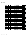
Write Map:
890GTR
8902/IM
Description
Address
Type
Command Word
1
DWord
Start Request
.00 Bool
Stop Request
.01 Bool
Fault Reset
.02 Bool
Voltage Control
.03 Bool
kW/kVAR Control
.04 Bool
.05 Bool
.06 Bool
.07 Bool
1
.08 Bool
.09 Bool
.10 Bool
.11 Bool
.12 Bool
.13 Bool
.14 Bool
.15 Bool
Watchdog
.00 Bool
.01 Bool
.02 Bool
.03 Bool
.04 Bool
.05 Bool
.06 Bool
.07 Bool
2
.08 Bool
.09 Bool
.10 Bool
.11 Bool
.12 Bool
.13 Bool
.14 Bool
.15 Bool
Condition Scale / Units
Bitwise
Momentary 1 = Start
Momentary 1 = Stop
Momentary 1 = Reset
Maintained 1 = DC Voltage Control Mode
Maintained 1 = kW / kVAR Control
Word
0 - 1
Byte
0 - 3
0
0
1
Pulse Train 1 HZ Pulse Train
2
1
3
Bit
~
0
1
2
3
4
5
6
7
8
9
10
11
12
13
14
15
16
17
18
19
20
21
22
23
24
25
26
27
28
29
30
31
890GTR Inverter Power Manual HA502996
4-7 Operations
Write Map (continued):
Id Demand
Iq Demand
DC Volts Demand
kW Demand
kVAR Demand
Nominal Line Voltage
Filter capacitance
I Loop Prop Gain
I Loop Int Gain
LVRT Trip 1 dt
LVRT Trip 2 dt
LVRT Trip 3 dt
LVRT Trip 4 dt
LVRT Trip 1 Volts
LVRT Trip 2 Volts
LVRT Trip 3 Volts
LVRT Trip 4 Volts
HVRT Nom Volts
HVRT Trip 1 Volts
HVRT Max Volts
HVRT Nom dt
HVRT Trip 1 dt
Over Freq Trip 1
Over Freq Trip 2
Over Freq Trip 1 Time
Over Freq Trip 2 Time
Under Freq Trip 1
Under Freq Trip 2
Under Freq Trip 1 Time
Under Freq Trip 2 Time
K Factor
890GTR Inverter Power Manual HA502996
3
5
7
9
11
13
15
17
19
21
23
25
27
29
31
33
35
37
39
41
43
45
47
49
51
53
55
57
59
61
63
Real
Real
Real
Real
Real
Real
Real
Real
Real
Real
Real
Real
Real
Real
Real
Real
Real
Real
Real
Real
Real
Real
Real
Real
Real
Real
Real
Real
Real
Real
Real
~
~
~
~
~
~
~
~
~
~
~
~
~
~
~
~
~
~
~
~
~
~
~
~
~
~
~
~
~
~
~
+- 1.0 = +- Inverter Rated Current
+- 1.0 = +- Inverter Rated Current
Volts DC
kW AC
kVAR AC
Nominal Vac (380Vac to 420Vac)
uF, 40 is nominal. 0 to turn off filter compensation
0.15 nominal
0.02 nominal
seconds, 0.16 nominal
seconds, 0.16 nominal
seconds, 1.0 nominal
seconds, 2.0 nominal
per unit voltage, 0.44 nominal
per unit voltage, 0.45 nominal
per unit voltage, 0.60 nominal
per unit voltage, 0.88 nominal
per unit voltage, 1.1 nominal
per unit voltage, 1.2 nominal
per unit voltage, 1.3 nominal
seconds, 1.0 nominal
seconds, 0.16 nominal
Hz, 60.5 or 50.5 nominal
Hz, 62 or 52 nominal
seconds, 0.16 nominal
seconds, 2.0 nominal
Hz, 59.5 or 49.5 nominal
Hz, 57 or 47 nominal
seconds, 2.0 nominal
seconds, 0.0 nominal
gain of reactive current during VRT. 0 nominal.
2
4
6
8
10
12
14
16
18
20
22
24
26
28
30
32
34
36
38
40
42
44
46
48
50
52
54
56
58
60
62
-
3
5
7
9
11
13
15
17
19
21
23
25
27
29
31
33
35
37
39
41
43
45
47
49
51
53
55
57
59
61
63
4
8
12
16
20
24
28
32
36
40
44
48
52
56
60
64
68
72
76
80
84
88
92
96
100
104
108
112
116
120
124
-
7
11
15
19
23
27
31
35
39
43
47
51
55
59
63
67
71
75
79
83
87
91
95
99
103
107
111
115
119
123
127
~
~
~
~
~
~
~
~
~
~
~
~
~
~
~
~
~
~
~
~
~
~
~
~
~
~
~
~
~
~
~
Operations
4-8
Emergency Power Off (EPO)
80 KW String Inverter
The 890GTR is equipped with an Emergency Power Off (EPO) circuit and High Voltage Interrupt Loop (HVIL) circuit.
The EPO circuit relies on the presence of an external 24 volt dc supply to maintain a healthy condition. If this supply is interrupted,
the 890GTR AC contactor immediately opens, disconnecting the Grid power. This action is accomplished through a direct hardware
connection and does not require software to function. However, the 890GTR software does monitor the EPO condition and will
disable the inverter if EPO 24 volt dc is not present. Note: EPO circuit does not disconnect the DC supply or the AC control
power. Removal of DC and/or control power should be incorporated in the system design if required.
The HVIL circuit is made up of two “dry” contacts integrated into the power connectors. If either power connector is not fully
engaged, then the HVIL circuit will open. It is recommended that the EPO and HVIL circuits are used together such that a break in
the HVIL circuit will also open the EPO circuit.
On the next page is a schematic representation of both EPO and HVIL circuits. Please note both EPO and HVIL circuits are polarity
insensitive.
890GTR Inverter Power Manual HA502996
4-9 Operations
Inverter
Inverter
3P AC power
connection
3P AC power
connection
AC HVIL
jumper
DC power
connection
Estop &
Power Supply
AC HVIL
jumper
DC power
connection
DC HVIL
jumper
E-Stop/HVIL
connector
Estop &
Power Supply
+24 V
(BMS)
24 V Return
(BMS)
1
2
2
K2 Main AC
Pilot relay
K2 Main AC
Pilot relay
3
3
4
4
5
5
6
6
Proposed E-Stop & HVIL Circuit
w BMS
890GTR Inverter Power Manual HA502996
E-Stop/HVIL
connector
1
BMS
BMS estop
Relay
DC HVIL
jumper
Example E-Stop & HVIL Circuit
Proposed E-Stop & HVIL Circuit
w/o BMS
Trips & Fault Finding
Chapter 5
5-1
Trips & Fault Finding
The following tables can be used to troubleshoot a loss of function, possibly due to a tripped circuit breaker or blown fuse. They list
the component identifier used in the circuit diagrams and the type, rating and location of each device.
•
Trips
•
Trips Table
•
Fault Finding
890GTR Inverter Power Manual HA502996
5-2 Trips & Fault Finding
Trips
What Happens when a Trip Occurs
When a trip occurs, the inverter’s power stage is immediately disabled causing output to stop. The trip is latched until action is taken
to reset it. This ensures that trips due to transient conditions are captured and the inverter is disabled, even when the original cause
of the trip is no longer present
Inverter Indications
If a trip condition is detected the unit displays and performs the following actions.
1. The programming block SEQ & REF::SEQUENCING LOGIC::TRIPPED signal is set to TRUE.
2. The FIRST TRIP parameter in the TRIPS STATUS function block displays the trip ID.
3. The HEALTH/TRIP LED on the respective Input and Output Modules indicates Red indicating a trip condition has occurred.
Inverter has Tripped
890GTR Inverter Power Manual HA502996
Trips & Fault Finding
5-3
Resetting a Trip Condition
Before a trip can be reset, the trip condition must be removed.
Note
A Heatsink Over-temperature trip may not reset immediately. The unit needs time to cool sufficiently.
Using Modbus TCP
To reset a trip in Remote Mode:
Remove the trip condition
Set Reset Fault bit True, and then return bit to False.
More than one trip can be active at any time. For example, it is possible for both the HEATSINK and the OVERVOLTAGE trips to be
active. Alternatively it is possible for the inverter to trip due to an OVERCURRENT error and then for the HEATSINK trip to become
active after the inverter has stopped (this may occur due to the thermal time constant of the heat sink).
890GTR Inverter Power Manual HA502996
5-4 Trips & Fault Finding
Trips Table
The following trips may occur to protect the inverter. The “STATE” can be read through Modbus.
STATE FAULT NAME
MEANING
0
OK
1
OVERVOLTAGE
The Inverter internal DC link voltage is too high.
2
UNDERVOLTAGE
The Inverter internal DC link voltage is too low.
3
OVERCURRENT
The output current being drawn from the Inverter
is too high.
4
HEATSINK
The inverter heatsink is too hot.
17
MOTOR OVERTEMP
Filter inductor temperature is too high.
24
DESAT OVER I
Abnormally high voltage drop across IGBT(s) due
to excessive current within IGBT module
25
VDC RIPPLE
Excessive DC link ripple
41
STACK TRIP
The inverter was unable to distinguish between an
overcurrent/desat or overvoltage trip
POSSIBLE REASON FOR TRIP
The supply voltage is too high.
Failure to synchronize properly to the line
The supply voltage is too low.
The supply voltage is missing.
Grid cables too long.
Possible maintenance required.
Short circuit of the output.
Excessive line disturbance.
Possible maintenance required.
Excessive ambient temperature.
Cooling fan failure.
Module assembly defect--maintenance required.
Excessive load.
Prolonged operation without forced cooling (check cooling fan
health)
Check setting of INVERT THERMIST parameter in I/O TRIPS
menu.
Break in filter inductor thermostat wire or defective thermostat.
Short circuit of the output.
Excessive line disturbance.
Possible maintenance required.
Defective DC supply.
Poor DC supply connection.
Short circuit of the output.
Excessive line disturbance.
Possible maintenance required.
890GTR Inverter Power Manual HA502996
Trips & Fault Finding
5-5
STATE FAULT NAME
MEANING
52
FIRMWARE ERROR
The firmware in the inverter has stopped executing
63
DRIVE CONFIG
Missing or corrupted configuration.
Re-load configuration.
Communication over Ethernet TCP (modbus) has
been lost or is not being updated.
Verify Modbus connection and ensure watchdog is serviced at
least three times per second.
External Estop circuit is not energized.
Verify 24 Volts DC is supplied to Estop (EPO) circuit.
CUSTOM TRIP 6
(DC OVERVOLTAGE)
CUSTOM TRIP 7
(DC
UNDERVOLTAGE)
VOLTAGE MAINS
LOST
DC bus voltage is above 840 volts dc while
inverter is running.
Check health of DC supply.
DC bus voltage is below 580 volts dc while
inverter is running.
Check health of DC supply and connections.
Positive and/or negative sequence values out of
range.
Check health of grid connection. Adjust trip values if needed.
91
HIGH VOLTAGE TRIP
Grid voltage too high.
Check health of grid connection. Adjust trip values in Grid
Control 2 block if needed.
92
LOW VOLTAGE TRIP
Grid voltage too low.
Check health of grid connection. Adjust trip values in Grid
Control 2 block if needed.
93
OVER FREQUENCY
Grid frequency too high.
Check health of grid connection. Adjust trip values in Grid
Control 3 block if needed.
94
UNDER FREQUENCY
Grid frequency too low.
Check health of grid connection. Adjust trip values in Grid
Control 3 block if needed.
65
68
70
71
90
CUSTOM TRIP 1
(EXERNAL
WATCHDOG
TIMEOUT)
CUSTOM TRIP 4
(ESTOP)
POSSIBLE REASON FOR TRIP
Corrupted firmware.
Re-install firmware.
Replace module.
If any fault is presented on Modbus other than those listed, Contact Parker EGT Product Support
890GTR Inverter Power Manual HA502996
5-6 Trips & Fault Finding
Checksum Fail
When the inverter powers-up, non-volatile memory is checked to ensure that it has not been corrupted. In the rare event of corruption
being detected, the inverter will not function. If this occurs, the preferred course of action is to swap the inverter and return the failed
unit to an authorized repair center. The repair center will have necessary spare parts and tools to restore the unit to working
condition.
890GTR Inverter Power Manual HA502996
Trips & Fault Finding
Fault Finding
Problem
Possible Cause
Remedy
Inverter will not power-up
Fuse blown
Check supply details, replace with
correct fuse.
Faulty cabling
Check all connections are correct and
secure.
Check cable continuity
Inverter fuse keeps blowing
Faulty cabling or connections wrong
Check for problem and rectify before
replacing with correct fuse
Faulty inverter
Contact Parker Hannifin EGT
Cannot obtain HEALTH state
Incorrect or no supply available
Check supply details
Inverter will not run at switch-on
Grid voltage not present
Check health of grid
Table 8-3 Fault Finding
890GTR Inverter Power Manual HA502996
5-7
5-8 Trips & Fault Finding
Front Panel LEDs
Status Lights
See following figure
{
DC Ready Status
AC Ready Status
+ -
Inverter is Synchronized to Grid
Control Power Present
Inverter has Tripped
890GTR Inverter Power Manual HA502996
Trips & Fault Finding
green
5-9
CNTRL
RUN
FAULT
DC STATUS
AC STATUS
control power is
present
inverter enabled
-
-
-
-
-
inverter tripped
-
-
control power is off
inverter disabled
inverter OK
-
-
-
-
-
DC bus voltage
present
inverter connected to
grid
-
-
-
DC bus voltage off
inverter not
connected to grid
red
OFF
red
OFF
890GTR Inverter Power Manual HA502996
6-1 Maintenance
Chapter 6
Routine Maintenance & Repair
This section provides general maintenance instructions. It does not provide detailed repair or diagnostic instructions.
•
Cleaning Instructions
•
Cleaning Instructions
•
The product has generally good resistance to acids, alkalis and oils at normal temperatures. The product can be
cleaned with:
•
Water
•
Diluted soap in water
•
General purpose chlorine-free cleaners that are mildly acidic, mildly alkaline, or neutral e.g. 409(R), Lysol(R),
Windex(R), etc.
•
Mild solvent-free degreasers e.g. Greased-Lightning(R)
Cleaning agents should be applied to a soft cloth and wiped across the product. DO NOT spray cleaning agents directly onto the
product. This will prevent chemicals from entering the enclosure. DO NOT apply cleaning agents to the exposed contacts of
connectors. Doing so may harm their performance.
•
Fan Maintenance & Replacement
•
Reactive Maintenance
•
Preventative Maintenance
•
Auxiliary Power Output Fuse Replacement
890GTR Inverter Power Manual HA502996
6-2 Maintenance
WARNING
:
IMPORTANT
WARNING: These servicing instructions are for use by qualified personnel only. To reduce the risk of electric shock, do
not perform any servicing other than that specified in the operating instructions unless you are qualified to do so.
IMPORTANT
All electrical work must be done in accordance with local, national, and/or international electrical codes by a qualified
electrician.
IMPORTANT
WARNING: Battery Strings can produce dangerous electrical voltage levels.
IMPORTANT
WARNING: Extreme Arc Flash and Shock Hazards
890GTR Inverter Power Manual HA502996
6-3 Maintenance
Cleaning Instructions
The product has generally good resistance to acids, alkalis and oils at normal temperatures. The product can be cleaned with:
•
Water
•
Diluted soap in water
•
General purpose chlorine-free cleaners that are mildly acidic, mildly alkaline, or neutral e.g. 409(R), Lysol(R),
Windex(R), etc.
•
Mild solvent-free degreasers e.g. Greased-Lightning(R)
Cleaning agents should be applied to a soft cloth and wiped across the product. DO NOT spray cleaning agents directly onto the
product. This will prevent chemicals from entering the enclosure. DO NOT apply cleaning agents to the exposed contacts of
connectors. Doing so may harm their performance.
890GTR Inverter Power Manual HA502996
6-4 Maintenance
Fan Maintenance & Replacement
Reactive Maintenance
When inverter signals a fan failure warning, inspect the inverter to determine which fan has failed and replace.
Preventative Maintenance
Replace all fans every 10 years in operation.
1. Disconnect the fan cables
2. Using a flat blade screwdriver remove the plastic guard to release it from the fan housing and discard.
890GTR Inverter Power Manual HA502996
6-5 Maintenance
3. Use a Torx 20 screwdriver to remove the two mounting screws
4. Remove the fan assembly and discard
5. Replace the fan assembly (LA474159U001) in the orientation shown. Ensure that the arrows are facing out away from
the product.
6. Re-use the mounting screws to fasten the fan assembly to the product. Torque to 1.5-2.5 Nm (1.1-1.8 lb-ft).
890GTR Inverter Power Manual HA502996
6-6 Maintenance
7. Install new plastic guard (BD465235) that is provided with replacement fans.
1.5 – 2.5 Nm (l.1 – 1.8 lb-ft)
890GTR Inverter Power Manual HA502996
6-7 Maintenance
Auxiliary Power Output Fuse Replacement
1. Use a slotted screwdriver, 5 mm (3/16 in), to remove the plastic fuse
cartridge by turning it 90° counter-clockwise. The fuse cartridge is spring
loaded and will pop out of the housing.
2. Remove and replace the fuse (CS352658U081) in the cartridge.
3. Replace the fuse cartridge by pushing it into the housing and turning 90°
clockwise. Do not overturn or over tighten as this will damage the plastic cap.
890GTR Inverter Power Manual HA502996
PPE
Chapter 7
7-1
PPE
This section provides general information on Personal Protective Equipment. Supervisors must assess the job tasks
performed by their workers and document what personal protective equipment (PPE) is necessary for the work being
performed. Each worker who is required to use PPE must be provided with training.
•
OSHA PPE REGULATIONS:
•
Guidelines
•
Training Requirements
•
Protection Requirements
•
OSHA Personal Protective Equipment Policy & Procedure (1910.0132- .0136)
•
Personal Protective Equipment Inspection
890GTR Inverter Power Manual HA502996
7-2 PPE
WARNING
:
IMPORTANT
All electrical work must be done in accordance with local, national, and/or international electrical codes by a qualified
electrician.
IMPORTANT
WARNING: Battery Strings can produce dangerous electrical voltage levels.
IMPORTANT
WARNING: Extreme Arc Flash and Shock Hazards
Flash Hazard Boundary 60”
Up to 24.46 Cal/cm2 at 18”
Class 3 PPE Level (Rated at 25 Cal/cm2) – 2 layers of clothing: cotton underwear + fire resistant shirt and
pants or coveralls + multilayer flash suit, VR gloves-tools, with appropriate flash hood.
Limited Approach Boundary 120”
Restricted Approach Boundary 12”
Prohibited Approach Boundary 1”
This section does not take the place of the specific training supervisors must provide their workers who use personal protective
equipment (PPE)
Refer to the most current revision of the OSHA informational booklet OSHA 3151-12R for information on personal protective
equipment (PPE).
890GTR Inverter Power Manual HA502996
PPE
7-3
OSHA PPE REGULATIONS:
•
•
•
•
•
•
•
•
1910.95 – Hearing
1910.132 – General
1910.133 – Eye and face
1910.134 – Respirator
1910.135 – Head
1910.136 – Foot
1910.137 – Electrical
1910.138 – Hand
Guidelines
It is important to note that engineering controls should be the primary method of establishing a safe workplace. Personal protective
equipment should only be used where engineering controls are not feasible.
General Requirements
1. Supervisors must assess the job tasks performed by their workers and document what personal protective
equipment (PPE) is necessary for the work being performed, document certification of hazard assessment which
identifies: the workplace evaluated, the person certifying that the evaluation has been performed, and the date(s) of
the hazard assessment.
2. Based on the hazards identified, the supervisor must document the appropriate level of PPE that has been selected
for all appropriate workers and inform them of the PPE selection decisions.
3. The selected PPE must be fitted to appropriate workers, maintained in a sanitary and reliable condition, and used
appropriately by workers as required.
4. Defective or damaged PPE must be removed from service immediately
5. Note: The OSHA standard has a non-mandatory Appendix B which contains example procedures for conducting a
hazard assessment.
890GTR Inverter Power Manual HA502996
7-4 PPE
Training Requirements
1. Each worker who is required to use PPE must be provided with training.
2. Training on PPE must include all of the following elements: when PPE is necessary; what PPE is necessary; how
to properly don, doff, adjust, and wear PPE; the limitations of the PPE; Any testing requirements (electrical PPE) ;
and the proper care, maintenance, useful life and disposal of the PPE.
3. Workers must demonstrate an understanding of the training and the ability to use PPE properly before being
allowed to perform work requiring the use of PPE. (Workers must be retrained when there is reason to believe that
they do not have the understanding or skill to use PPE properly)
4. Retraining must be conducted whenever changes in the workplace or changes in types of PPE make previous
training obsolete. NFPA 70E states that retraining is required in intervals not to exceed three years.
5. There must be written certification for each person who has received PPE training that includes the following: a
statement indicating the person understood the training; the name of the person trained; the date(s) of the training;
and the subject of the certification.
Protection Requirements
Head, Foot, and Hand Protection
1. Protective helmets must be used wherever there is the possible danger of head injury from impact, or from falling or
flying objects, or from electrical shock and burns.
2. Protective helmets must meet the American National Standard for Personnel Protection Requirements, ANSI
Z89.1-1986 (Protective Headwear for Industrial Workers).
3. Protective footwear must be used wherever there is the danger of foot injuries due to falling or rolling objects,
objects piercing the sole, or where feet are exposed to electrical hazards.
890GTR Inverter Power Manual HA502996
PPE
7-5
4. Protective footwear must meet the requirements of the American National Standard for Personal Protection-Protective Footwear, ANSI Z41-1991.
5. Appropriate protective gloves must be used wherever there is the danger to hands of exposure to hazards such as
those from skin absorption of harmful substances, severe cuts or lacerations, severe abrasions, punctures,
chemical burns, thermal burns, and harmful temperature extremes.
Eye and Face Protection
1. Workers are required to wear appropriate eye protective devices while participating or observing activities which
present a potential eye safety hazard.
2. All protective eye and face devices must comply with ANSI Z87.1-1989.
Note: Regular prescription eye glasses do not meet this requirement. Goggles or other protective glasses meeting the American
National Standard must be worn over-top prescription eye glasses.
Hearing Protection
1. Whenever feasible, employers are required to reduce the noise at the source through engineering solutions. When
this is not possible or economically feasible it is acceptable to use hearing protection as a temporary solution. The
term hearing conservation as defined by OSHA includes the following aspects, which the employer is responsible
to carry out:
A. Monitoring of the noise environment. If the TWA (Time Weighted Average) noise level is exceeding 85
dB(A), a hearing conservation program is required.
B. Several different types of hearing protectors are required to be offered to the employees. The employees are
required to use the hearing protection, and the employer is responsible for the enforcement.
890GTR Inverter Power Manual HA502996
7-6 PPE
C. Establishing a baseline audiogram for each noise exposed employee, and annual hearing tests thereafter in
order to monitor the hearing health of the employees.
D. Take corrective action when it is concluded that a noise induced hearing damage is occurring. Corrective
action can entail further education and training in the use and importance of full time use of hearing
protection. Seeking the use of hearing protectors better suited to the environment and the individual.
OSHA's Permissible Noise Exposure
dB
Hours Exposure
90 dB
8.0 hours
92 dB
6.0 hours
95 dB
4.0 hours
97 dB
3.0 hours
100 dB
2.0 hours
102 dB
1.5 hours
105 dB
1.0 hours
110 dB
30 minutes
115 dB
15 minutes
Posting Requirements
1. All areas and equipment requiring the use of PPE devices shall be posted with a sign indicating this requirement.
Note: The warning signs on the enclosure should be inspected at each visit to ensure that the warning signs have not become
illegible.
890GTR Inverter Power Manual HA502996
PPE
7-7
OSHA Personal Protective Equipment Policy & Procedure (1910.0132- .0136)
•
Personal Protective Equipment, or PPE, must be provided, used, and maintained in a sanitary and reliable condition when
there is a reasonable probability of injury or illness that can be prevented by such protection.
•
PPE includes protection for eyes, face, head and extremities, protective clothing, respiratory devices, protective shields and
barriers.
•
When employees provide their own PPE, the employer is responsible to assure its adequacy.
•
All personal protective equipment shall be of safe design and construction for the work to be performed. See ANSI Z133 as
well as the other ANSI standards it references for details.
•
The employer has to assess the workplace (including the shop) to determine if hazards are present, or are likely to be
present, which necessitate the use of personal protective equipment (PPE). If such hazards are present, or likely to be
present, the employer shall:
1. Select, and have each affected employee use, the types of PPE that will protect the affected employee from
the hazards identified;
2. Communicate selection decisions to each affected employee; and,
3. Select PPE that properly fits each affected employee.
•
The employer has to verify that the required workplace hazard assessment has been performed through a written
certification that identifies the workplace evaluated; the person certifying that the evaluation has been performed; the
date(s) of the hazard assessment; and, which identifies the document as a certification of hazard assessment.
890GTR Inverter Power Manual HA502996
7-8 PPE
Personal Protective Equipment Inspection
All PPE is to be inspected prior to and after each use. If the PPE is damaged, do not use it. Damaged PPE must
be replaced.
Hard Hats
•
Class G (or A) helmets help protect against impact and low-voltage electrical conductors. Shells are proof-tested at
2200 volts of electrical charge.
•
Class E (or B) helmets help protect against impact and high-voltage electrical conductors. Shells are proof-tested
at 20,000 volts.
•
Type 1 Hardhats protect against impacts to the top of the head.
•
Type 2 Hardhats protect the head from top and side impacts.
INSPECTION:
•
The suspension system is not excessively worn
•
The straps are not torn
•
The plastic components are not broken
•
The helmet has not sustained damage from an impact, poor treatment, or excessive use
•
The shell is not dented, cracked or broken
•
The shell has not been damaged by high temperature
•
The shell has not been degraded by UV light (white chalky substance on the surface of the shell)
890GTR Inverter Power Manual HA502996
PPE
7-9
Hearing (must be ANSI Z87 compliant).
•
Ear Plugs and Ear Muffs individually protect against noise level of 28-30 dB (A).
•
For greater levels of protection Ear Plugs and Ear Muffs can be worn in conjunction to protect against higher noise
levels.
INSPECTION:
•
The Ear plugs do not have cracks, hardening, discoloration, rips, cuts, tears, holes, or microbial growth (bad odor
emanating from the Ear Plugs).
Eyewear (must be ANSI Z87 compliant)
•
Safety Glasses and Goggles protect against moving particles and objects.
•
Polycarbonate Face Shields protect against moving particles and objects
•
Polycarbonate Face Shields with a reflective coating protect against moving particles and objects and against
radiant energy (UV light and heat).
•
Arc Flash Category 2 Face Shield with a reflective coating is designed to attach to a standard hardhat and protects
against moving particles and objects and against radiant energy at a rating of 8 Cal/cm2
INSPECTION:
•
The eyewear does not have broken or damaged components.
•
The eyewear does not have elastic straps that are excessively worn or splitting.
•
The eyewear does not have lenses that are scratched or abraded in a manner that would obstruct vision.
890GTR Inverter Power Manual HA502996
7-10 PPE
Arc Flash Hood
•
Arc Flash Hood with a Face Shield with a reflective coating and a 15” front bib fits over a standard hard hat and
protect against moving particles and objects and against radiant energy at a rating of 8, 12, 20, 40 Cal/cm2. The
hood / bib material depends on the Category the Arc Flash Hood is designed to protect against and can be a
combination of Indura, Nomex, Protera, RevoLite, TuffWeld and Kevlar.
INSPECTION:
•
The face shield is not broken or damaged.
•
The eyewear does not have elastic straps that are excessively worn or splitting.
•
The face shield is not scratched or abraded in a manner that would obstruct vision.
•
The material of the hood does not have burns, cracks, hardening, discoloration, rips, cuts, tears, holes or microbial
growth (bad odor emanating from the Arc Flash Hood).
890GTR Inverter Power Manual HA502996
PPE
7-11
Gloves
(It will be necessary to wear one type of glove over another)
Class 00 Gloves provide protection up to 500 volts and are constructed of rubber blends.
Class 0 Gloves provide protection up to 1000 volts and are constructed of rubber blends.
Class 1 Gloves provide protection up to 7500 volts and are constructed of rubber blends.
Class 2 Gloves provide protection up to 17,000 volts and are constructed of rubber blends.
Arc Flash Fire Resistant Gloves are not electrically insulated. They are rated in Cal/cm2 ratings of 12, 20, 36, 40,
51 Cal/cm2. They are constructed of Indura.
Leather gloves are not electrically insulated. They protect Electrical insulating gloves from damage due to
abrasions or puncture.
INSPECTION:
The gloves do not have cracks, hardening, discoloration, rips, cuts, tears, pin-holes or microbial growth (bad odor
emanating from the glove).
890GTR Inverter Power Manual HA502996 7-12 PPE
Footwear (must be ANSI Z41 compliant).
•
Hard Toe Boots protect against injury from falling, rolling, or lacerating objects. The hard toes are constructed of
metal or acrylics. The boot material is available in leather, synthetic leather, chemical resistant material, or cut
resistant materials such as Kevlar.
INSPECTION:
•
The footwear does not have cracks, hardening, discoloration, rips, cuts, tears, holes, or microbial growth (bad odor
emanating from the footwear).
890GTR Inverter Power Manual HA502996
PPE
Class 1 Nomex
7-13
Class 2 Indura Underwear
Arc Flash Undergarments
•
Arc Flash Undergarments are available, but not specifically required. Undergarments made of natural, non-melting
fabrics are acceptable.
•
Undergarments fit under clothing and protect against radiant energy at a rating of 4 - 18 Cal/cm2. The garment
material (typically Indura or Nomex) depends on the Calorie-rating. Material weight ranges from 4-8 oz.
INSPECTION:
•
The material does not have burns, discoloration, rips, cuts, tears, holes or microbial growth (bad odor emanating
from the garment).
890GTR Inverter Power Manual HA502996
7-14 PPE
Class 1 Nomex Clothing
Class 2 Indura Clothing
Arc Flash Garments
•
Arc Flash garments are shirts, pants or socks that protect against radiant energy at a rating of 4-12 Cal/cm2. The
garment material (typically Indura or Nomex) depends on the Calorie-rating. Material weight ranges from 4-9 oz.
INSPECTION:
•
The material does not have burns, discoloration, rips, cuts, tears, holes or microbial growth (bad odor emanating
from the garment).
890GTR Inverter Power Manual HA502996
PPE
Category 1 Nomex Coveralls
7-15
Category 2 Protera
Arc Flash Coveralls
•
Coveralls fit over clothing and protect against radiant energy at a rating of 5.7 - 12.3 Cal/cm2. The coverall material
(typically Indura or Nomex) depends on the Calorie-rating. Material weight ranges from 4-8 oz.
INSPECTION:
•
The material does not have burns, discoloration, rips, cuts, tears, holes or microbial growth (bad odor emanating
from the garment).
890GTR Inverter Power Manual HA502996
7-16 PPE
Category 3 Indura
Category 4 Indura Arc Flash
Category 4 Arc Flash Suit
Arc Flash Suit
•
An Arc Flash Suit fits over clothing and is comprised of a coat and a pair of bibs. The Arc Flash Suit protects
against radiant energy at a rating of 8-40 Cal/cm2. The material depends on the Calorie-rating the Arc Flash Suit is
designed to protect against and is typically constructed of multiple layers of a combination of Indura, Nomex,
Protera, RevoLite, TuffWeld or Kevlar. Material weight ranges from 7 oz. For an 8 Cal/cm2 Category 2 Arc Flash
Suit to 13 oz. Lined with 5.5 oz. for a 40 Cal/cm2 Category 4 Arc Flash Suit.
INSPECTION:
•
The material does not have burns, discoloration, rips, cuts, tears, holes or microbial growth (bad odor emanating
from the garment).
890GTR Inverter Power Manual HA502996
PPE
7-17
Arc Flash Balaclava
•
Arc Flash Balaclava a style of head protection worn under a standard hard hat with a goggles or a Face Shield with
a reflective coating that protects against moving particles and objects and against radiant energy at a rating of 8,
12, 20, 40 Cal/cm2. The balaclava material and number of layers depend on the Category the Arc Flash Hood is
designed to protect against and can be a combination of Indura, Nomex, Protera and Kevlar.
INSPECTION:
•
The material of the balaclava does not have burns, cracks, hardening, discoloration, rips, cuts, tears, holes or
microbial growth (bad odor emanating from the Arc Flash Balaclava).
NOTE: NFPA 70E 2012 [Section 130.7(C)(13)(b)]: When inside the AFB and anticipated exposure is 12 cal/cm² or less,
employees will now be required to wear either an arc-rated balaclava with an arc rated, wrap-around style face shield
(protecting face, chin, ears, forehead and neck), or an arc-rated hood like that used in an arc flash suit. But when
anticipated incident energy exposure is greater than 12 cal/cm², then an arc-rated hood will now be required.
890GTR Inverter Power Manual HA502996
8-1 Ethernet
Chapter 8
890GTR Inverter Power Manual HA502996
Ethernet
Ethernet
8-2
Objective
Set Ethernet IP address for an 890 inverter fitted with an Ethernet fieldbus option card.
Procedure
Ethernet fieldbus option card is standard on the 890GTR.
There are three options for setting the Ethernet IP address:
Hardcoded via the VM configuration (this is the most commonly used method). (page 8-3)
Set via DSE. (page 8-4)
Set via BootP server.(page 8-5)
890GTR Inverter Power Manual HA502996
8-3 Ethernet
Hardcoded Option (for 890 hardware)
1. In the configuration insert an Ethernet function block:
2. Open the Ethernet function block and set the IP address parameter to the desired IP address.
3. You should also set the Subnet mask parameter since some versions of firmware require this in order to set the IP address.
Generally, 255.255.255.0 is a good default value to use.
See the Ethernet function block help for more details.
890GTR Inverter Power Manual HA502996
Ethernet
8-4
DSE Option
Connect to the module and select “Set IP Address…” in the “Command” menu. The following dialog should come up:
Enter the desired IP address and click on OK. Note that if you are connected to the module via the Ethernet, you may have to exit
DSE and/or restart the module for DSE to connect after changing the address. This method is not supported for all versions of
firmware and may be overridden by a Hardcoded address (see above) or a BootP set address (see below) when the module is restarted.
890GTR Inverter Power Manual HA502996
8-5 Ethernet
BootP Option (for 890 hardware)
BootP is not available for version 2.4, 3.12, 4.1 and 5.2 (and earlier) firmware. BootP will only be used if the Hardcoded address (see
above) is 0.0.0.0 and the “BootP support” parameter in the Ethernet function block is set to “STATIC” or “DYNAMIC”:
If “BootP support” parameter is set to “STATIC”, the module will attempt to obtain an IP address via BootP whenever a configuration
is installed. If an IP address is obtained from a BootP server, it is saved and used on subsequent power cycles. If “BootP support”
parameter is set to “DYNAMIC”, the module will attempt to obtain an IP address via BootP whenever a configuration is installed or
power is cycled.
890GTR Inverter Power Manual HA502996
Inverter Keypad
Appendix A
A-1
Inverter Keypad
The 890GTR is not equipped with a keypad. Only authorized personnel can install or use a keypad with an 890GTR. Details of
keypad operation can be found in the 890GTB Grid Tie Product manual HA473578U201.
890GTR Inverter Power Manual HA502996
B-1 Programming
Appendix B
Programming
The 890GTR Grid-Tie Inverter uses a small subset of the functionality of the AC890 control platform. This appendix highlights the
functions used for grid-tie applications.
•
Configure the Inverter
•
Programming with Block Diagrams
890GTR Inverter Power Manual HA502996
Programming
B-2
Configure the Inverter
IMPORTANT: Inverters are shipped pre-configured from the factory. This section is for reference only!
An 890GTR grid-tie inverter uses a combination of native 890 function blocks and library function blocks for control. If you receive a replacement
control board, you must configure it to your application. To do this, use DSELite supplied on the CD.
Configure the Inverter
The simplest method for configuring an inverter is to reinstall the original configuration using DSELite. The DSELite configuration tool has a
full Help system. Insert the DSELite disk into your PC and follow the on-screen instructions.
You can use the tool to manually set-up the inverter so that it meets the requirements for your application. This involves connecting input
and output terminals to desired function block parameters, creating sequencing logic, configuring communication channels, and entering
desired parameter values.
This manual describes inverter functionality programmed into a standard Parker EGT grid-tie inverter.
Connecting to a PC
Connect the Grid-Tie inverter via the USB port on the front of the inverter to your PC using an approved USB lead.
Programming with Block Diagrams
Block diagram programming provides a visual method of planning the software to suit your application. The blocks described here are those
blocks used by the Shipping Configuration(s) in DSELite (the configuration shipped with your product may vary). The figure below shows a
typical block diagram as seen in DSELite.
890GTR Inverter Power Manual HA502996
B-3 Programming
The processes performed by the shipping configuration are
represented as a block diagram, consisting of function blocks
and links:
• Each function block contains the parameters
required for setting-up a particular processing
feature. Sometimes more than one instance of
a function block is provided for a feature, for
example multiple digital inputs.
• Software links are used to connect the
function blocks. Each link transfers the value of
an output parameter to an input parameter of
another (or the same) function block.
Each individual block is a processing feature; that is, it
takes the input parameter, processes the information,
and makes the result available as one or more output
parameters.
Programming Rules
The following rules apply when programming:
• Function block output parameter values cannot be changed (because they are a result of the processing in the function
block).
• Function block input parameter values that receive their values from an internal link in the Block Diagram cannot be changed
(as they will change back to the value they receive from the link when the inverter is running).
Function Block Descriptions
For function block descriptions, refer to Firmware Version 5.1 Manual (HA473746U001) Section 3.
890GTR Inverter Power Manual HA502996
Programming
B-4
Function Blocks
Page
Block
I/O Hardware Configuration
3-15
ANALOG INPUT
3-15,18 I/O CONFIGURATION
Sequencing/Referencing
Page
Block
Page
Block
Page
Block
3-18
ANALOG OUTPUT
3-24
DIGITAL INPUT
3-25
DIGITAL OUTPUT
3-19
3-46
LOCAL CONTROL
3-55
SEQUENCING
LOGIC
3-31
3-42
ENERGY METER
INVERTER
3-32
3-47
FEEDBACKS
MPPT
3-36
3-52
GRID CONTROL
PATTERN GEN
3-34
FIELDBUS
3-40
I/O TRIPS
3-59
TRIPS HISTORY
3-60
TRIP STATUS
3-27
DISPLAY SCALE
3-49
OP STATION
3-50
OPERATOR MENU
3-30
EMC CAPACITORS
AUTO RESTART
Inverter Control
3-22
CURRENT LIMIT
3-41
INVERSE TIME
3-54
POWER LIMIT
Communications
3-21
COMMS CONTROL
Trips
3-23
CUSTOM TRIPS
Menus
3-14
ACCESS CONTROL
3-58
SETPOINT DISPLAY
Miscellaneous
3-44
INVERTER CONFIG
890GTR Inverter Power Manual HA502996
C-1 Compliance
Appendix C
Compliance
•
Introduction
•
Europe
•
Australia & New Zealand
•
EMC
•
EMC General Installation Considerations
•
Increasing Grid Cable Length
•
Certificates
890GTR Inverter Power Manual HA502996
Compliance
C-2
Introduction
890GTR Inverters are certified as being compliant with the regulated market requirements in:
Europe
Inverters are CE certified as being compliant with
•
The Low Voltage Directive 2006/95/EC
•
The EMC Directive 2004/108/EC
USA
•
This release of this product has NOT been certified by Underwriters Laboratory Standard UL508C for Power
Conversion Equipment
Canada
•
This release of this product has NOT been certified by Canadian Standards Association C22.2 No.14 for Industrial
Control Equipment
Australia & New Zealand
•
CTick mark indicating EMC compliance is validated by compliance with the European Harmonised
Standards for EMC
Rest of the world
•
Compliance may be certified for any countries where certification is based on CISPR (IEC) standards
890GTR Inverter Power Manual HA502996
C-3 Compliance
European Compliance
CE Marking
The CE marking is placed upon the product by Parker Hannifin Manufacturing Ltd to facilitate its free movement
within the European Economic Area (EEA). The CE marking provides a presumption of conformity to all applicable
directives. Harmonized standards are used to demonstrate compliance with the essential requirements laid down in
those relevant directives.
It must be remembered that there is no guarantee that combinations of compliant components will result in a
compliant system. This means that compliance to harmonised standards will have to be demonstrated for the system
as a whole to ensure compliance with the directive.
Local wiring regulations always take precedence.
Where there are any conflicts between regulatory standards for example earthing
requirements for electromagnetic compatibility, safety shall always take precedence.
Low Voltage Directive
When installed in accordance with this manual the product will comply with the low voltage directive 2006/95/EC.
Protective Earth (PE) Connections
Only one protective earth
conductor is permitted at each protective earth terminal contacting point.
The product requires a protective earth conductor cross section of at least 10mm²
Compliance with harmonised standards provides a "presumption of conformity” and is the route which has been
adopted by Parker Hannifin Manufacturing Limited certification (DoC) is supported by tests undertaken in accordance
with harmonised standard BS EN50178:1998.
890GTR Inverter Power Manual HA502996
Compliance
C-4
EMC Directive
When installed in accordance with this manual the product will comply with the electromagnet compatibility directive
2004/108/EC.
The following information is provided to maximise the Electro Magnetic Compatibility (EMC) of systems in their
intended operating environment, by minimising their emissions and maximising their immunity.
EMC Compliance
WARNING
In a domestic environment, this product may cause radio interference, in which case supplementary mitigation measures may be
required.
Definitions
Category C1
PDS (Power Drive System) of rated voltage less than 1000V, intended for use in the first environment
Category C2
PDS (Power Drive System) of rated voltage less than 1000V, which is neither a plug in device nor a movable device and, when used
in the first environment, is intended to be installed and commissioned only by a professional.
Note: A professional is a person or an organisation having necessary skills in installing and/or commissioning power drive systems, including their EMC aspects.
Category C3
PDS (Power Drive System) of rated voltage less than 1000V, intended for use in the second environment and not intended for use in
the first environment.
Category C4
PDS (Power Drive System) of rated voltage equal to or above 1000V, or rated current equal to or above 400A, or intended for use in
complex systems in the second environment.
First Environment
Environment that include domestic premises, it also includes establishments directly connected without transformers to a low-voltage
power supply network which supplies buildings used for domestic purposes.
890GTR Inverter Power Manual HA502996
C-5 Compliance
Note: Houses, apartments, commercial premises or offices in a residential building are examples of first environment locations.
Second Environment
Environment that includes all establishments other than those directly connected to a low-voltage power supply network which
supplies buildings used for domestic purposes.
Note: Industrial areas, technical areas of any building fed from a dedicated transformer are examples of second environment
locations.
The 890GTR is generally a category C3 apparatus. Some of the equipment with higher ratings might be classified in Category C4;
but for certification, and as an aid to builders of complex system, the emission limits and immunity levels associated with category C3
have been applied.
Parker Hannifin Manufacturing Limited certification (DoC) is supported by tests undertaken in accordance with harmonised standard
BS EN61800-3.
890GTR Inverter Power Manual HA502996
Compliance
C-6
Australia & New Zealand
A Mutual Recognition Agreement in relation to conformity assessment, certificates and markings between Australia and the European
Community was signed on June 1, 1998 and entered into force on January 1, 1999. Sectoral Annexes of the MRA cover: medicinal
products, medical devices, telecommunications terminal equipment, low voltage equipment (i.e. electrical safety), electromagnetic
compatibility (EMC), machinery, pressure equipment and automotive products.
EMC Standards
Extract from Mandatory Australian Communications Authority standards.
Product
European
International
AS/NZS
Industrial, scientific, and medical (ISM) equipment
EN 55011
CISPR 11
2064
Note 3
Information technology equipment
EN 55022
CISPR 22
3548
Note 2
Generic (residential, commercial, and light industry)
EN 50081.1
IEC 61000-6-3
4251.1
Generic (industrial environments)
EN 50081-2
IEC 61000-6-4
4251.2
Adjustable speed electrical power drive systems
EN 61800-3
IEC 61800-3
0
Parker Hannifin Manufacturing Limited certification (DoC) is supported by tests undertaken in accordance with harmonised standard
BS EN61800-3.
890GTR Inverter Power Manual HA502996
C-7 Compliance
EMC
Emissions Limits
Conducted
Frequency (MHz)
DB (µV)
Quasi Peak
where I ≤100A
0.15 - 0.5
0.5 - 5.0
5.0 - 30.0
decreasing with log of frequency to:
where I ≥100A
0.15 - 0.5
0.5 - 5.0
5.0 - 30.0
Average
Product Specific
EN 61800-3
90
76
80
100
86
90
70
60
130
125
115
Category C3
Table 17
120
115
105
Where these levels are too high and to ensure compatibility with other equipment, EMC filters are available from Parker.
Radiated
Frequency (MHz)
DB (µV)
Quasi Peak
30≤ f- ≤230
230≤ f- ≤1000
50
60
Product Specific
EN 61800-3
Category C3
(Table 18)
Measured at 10m
Where these levels are too high and to ensure compatibility with other equipment, Parker can advise on suitable counter-measures.
890GTR Inverter Power Manual HA502996
Compliance
C-8
EMC Immunity Levels
Port
Enclosure port
Power ports
Power
interfaces
Signal
interfaces
ESD
IEC 61000-4-2
Radio-frequency electromagnetic field,
amplitude modulated.
Fast transient-burst
b
Surge
1,2/50 µs, 8/20 µs
e
Conducted radio-frequency common mode
IEC 61000-4-3
see also 5.3.4
IEC 61000-4-4
IEC 61000-4-5
IEC 61000-4-6
see also 5.3.4
Fast transient-burst
e
IEC 61000-4-4
Fast transient-burst
e
IEC 61000-4-4
Conducted radio-frequency common mode
Ports for
process
measurement
control lines
Basic standard
for test method
Phenomenon
Fast transient-burst
f
e
e
Surge
1,2/50 µs, 8/20 µs
e
Conducted radio-frequency common mode
IEC 61000-4-6
see also 5.3.4
IEC 61000-4-4
IEC 61000-4-5
IEC 61000-4-6
see also 5.3.4
Performance
(acceptance
criterion)
Level
4 kV CD or 8 kV AD
if CD impossible
80 MHz to 1000 Mhz 10 V/m
80% AM (1 kHz)
a
2 kV/5 kHz
c
1 kV
d
2 kV
0,15 MHz to 80 MHz
10 V
80 % AM (1 kHz)
2 kV/5 kHz
Capacitive clamp
1 kV/5 kHz
Capacitive clamp
0,15 MHz to 80 MHz
10 V
80 % AM (1 kHz)
2 kV/5 kHz
Capacitive clamp
d,f
1 kV
B
0,15 MHz to 80 MHz
10 V
80 % AM (1 kHz)
A
A
B
B
A
B
B
A
B
B
CD : contact discharge
AD : air discharge AM : amplitude modulation
a Power ports with current rating < 100 A: direct coupling using the coupling and decoupling network. Power ports with current rating ≥ 100 A:
direct coupling or capacitive clamp without decoupling network. If the capacitive clamp is used, the test level shall be 4 kV/2,5 kHz.
b Applicable only to power ports with current consumption , 63 A during light load test conditions as specified in 5.1.3. The rated impulse voltage of
the basic insulation shall not be exceeded (see IEC 60664-1).
c
Coupling line-to-line.
d Coupling line-to-earth.
e Applicable only to ports or interfaces with cables whose total length according to the manufacturer's functional specification may exceed 3 m.
f
Applicable only to ports with cables whose total length according to the manufacturer's functional specification may exceed 30 m. In the case of a
shielded cable, a direct coupling to the shield is applied. This immunity requirement does not apply to fieldbus or other signal interfaces where
the use of surge protection devices is not practical for technical reasons. The test is not required where normal functioning cannot be achieved
because of the impact of the coupling/decoupling network on the equipment under test (EUT).
Minimum immunity requirements for PDSs intended for use in the second environment
890GTR Inverter Power Manual HA502996
C-9 Compliance
890GTR EMC Compliance
•
Ethernet cable:
Cat 5 shielded, maximum recommended length of 100 meters. EMC testing requires ferrite for radiated immunity
•
Estop/HVIL cable:
24Vdc signal used to pull in main contactor pilot relay. Shielding not required. Maximum recommended length 30 meters.
•
DC power cables:
Typical installation length of 1 meter. Shielding not required. Maximum recommended length of 5 meters.
•
AC power cables:
Shielding not required. Maximum recommended length of 30 meters.
Conducted Emissions Profile (Unfiltered Product)
890GTR Inverter Power Manual HA502996
Compliance
C-10
890GTR Inverter Power Manual HA502996
C-11 Compliance
Harmonic Information
Supply Harmonic Analysis (890 GTR) Nominal frequency = 60/50 Hz, Fundamental primary current = 128 Arms
890GTR Inverter Power Manual HA502996
Compliance
C-12
EMC General Installation Considerations
Earthing Requirements
IMPORTANT
Protective earthing always takes precedence over EMC screening.
Protective Earth (PE) Connections
Note
In accordance with installations to EN60204, only one protective earth conductor is permitted at each protective earth
terminal contacting point.
Local wiring regulations take precedence and may require the protective earth connection of the transformer to be connected locally,
i.e. not as specified in these instructions. This will not cause shielding problems because of the relatively high RF impedance of the
local earth connection.
EMC Earth Connections
For compliance with EMC requirements, we recommend that the “0V/signal ground” be separately earthed. When a number of units
are used in a system, these terminals should be connected together at a single, local earthing point.
Control and signal cables for the encoder, all analogue inputs, and communications require screening with the screen connected only
at the inverter end. However, if high frequency noise is still a problem, earth the screen at the non-VSD end via a 0.1µF capacitor.
Note
Connect the screen (at the VSD end) to the VSD protective earth point, and not to the control board terminals.
Cabling Requirements
Planning Cable Runs
•
•
•
•
•
Use the shortest possible grid cable lengths.
Keep electrically noisy and sensitive cables apart.
Keep electrically noisy and sensitive parallel cable runs to a minimum. Separate parallel cable runs by at least 0.25 metres.
For runs longer than 10 metres, separation should be increased proportionally. For example if the parallel runs were 50m,
then the separation would be (50/10) x 0.25m = 1.25m.
Sensitive cables should cross noisy cables at 90°.
Never run sensitive cables close or parallel to the grid or dc link conductors for any distance.
890GTR Inverter Power Manual HA502996
C-13 Compliance
•
•
Never run supply, dc link or grid cables in the same bundle as the signal/control and feedback cables, even if they are
screened.
Ensure EMC filter input and output cables are separately routed and do not couple across the filter.
Increasing Grid Cable Length
Because cable capacitance and hence conducted emissions increase with grid cable length, conformance to EMC limits is only
guaranteed with the specified ac supply filter option up to a maximum cable length as specified in Appendix E: “Technical
Specifications".
This maximum cable length can be improved using the specified external input or output filters.
Screened/armoured cable has significant capacitance between the conductors and screen, which increases linearly with cable length
(typically 200pF/m but varies with cable type and current rating).
Long cable lengths may have the following undesirable effects:
•
•
•
•
Tripping on `overcurrent’ as the cable capacitance is charged and discharged at the switching frequency.
Producing increased conducted emissions that degrade the performance of the EMC filter due to saturation.
Causing RCDs (Residual Current Devices) to trip due to increased high frequency earth current.
Producing increased heating inside the EMC ac supply filter from the increased conducted emissions.
These effects can be overcome by adding chokes or output filters at the output of the VSD.
Mitigating Radiated Emissions
Equipment Placement
Do not place magnetic/electric field sensitive equipment within 0.25 meters of the following parts of the
890GTR system:
890GTR Inverter Power Manual HA502996
•
890GTR
•
Input or output chokes/transformers
•
The cable between 890GTR and Batteries (even when screened/armored)
•
DC link connections (even when screened/armored)
•
Relays and contactors (even when suppressed)
Compliance
C-14
890GTR Inverter Power Manual HA502996
D-1 Associated Equipment
Appendix D
Associated Equipment
•
General wiring and circuit protection
•
Isolation transformer
•
DC supply
•
Uninterruptable Power Supply (UPS)
•
AC Disconnect
•
System ground fault detection
•
Ethernet connection:
890GTR Inverter Power Manual HA502996
Associated Equipment
D-2
**WARNING: Parker Inverters must be installed using wiring methods according to the
requirements of ANSI/NFPA 70, Canadian Electrical Code Part I, or other appropriate local or
national electrical codes. It is the responsibility of the installer to ensure installation is designed
and performed in compliance with these standards.
**Danger: The 890GTR has multiple sources of power that must be disconnected before
servicing. Failure to remove all power and ensure the unit is safe to approach could result in
serious injury or death.
**Danger: It is the responsibility of the site installer and site operator to determine arc flash risk
levels and ensure safety procedures are put into place and followed. Failure to set up and follow
safety procedures could result in serious injury or death.
General wiring and circuit protection
Wiring codes typically require conductors and overload devices to be sized at least 125% of the continuous full load current rating of
the device. The 890GTR has a maximum full load continuous current rating of 128 A (rms) on the AC grid side. The maximum full
load current on the DC side is 160 A (dc). Additionally, the unit is capable of 150% overload for 1 minute, therefore any circuit
protection should accommodate this overload period without issue.
Isolation transformer
The 890GTR requires a three phase isolation transformer between the AC grid and its output. This transformer should step down the
grid voltage to 400 V. The transformer should have a minimum K-factor of 4. An un-bonded delta winding configuration is
recommended on the inverter side of the transformer. Multiple 890GTR units can be connected to the same transformer winding
provided the DC supply for each 890GTR is floating (not bonded to ground). If the DC supplies are grounded, then each 890GTR
must be connected on a separate un-bonded isolated transformer winding. Grounding of both the AC and DC supplies can result in
catastrophic damage to the invertor(s).
890GTR Inverter Power Manual HA502996
D-3 Associated Equipment
DC supply
The DC bus capacitors inside the 890GTR must be pre-charged to the DC supply voltage before the DC supply can be applied.
Failure to properly pre-charge the 890GTR could result in damage to the inverter or associated equipment. DC Overload and short
circuit protection must be provided external to the 890GTR. The DC supply must also have a means of disconnecting during
intended shutdown and fault events. Most battery systems require a Battery Management System (BMS). The BMS must be
capable of operation with common-mode voltage swings of up to 1200 volts.
Uninterruptable Power Supply (UPS)
Blackstart or low voltage ride through events require that a UPS provide control power for the 890GTR. This UPS must be capable of
supplying 150 VA (120 W) for each 890GTR. The 890GTR provides 120 Vac output that is generated by a 750 VA control
transformer connected to grid power. This 120 V output is intended to supply power to the UPS or other associated equipment.
AC Disconnect
A grid disconnect is required. This disconnect is usually incorporated with either the AC breaker or fuse assembly.
890GTR Inverter Power Manual HA502996
Associated Equipment
D-4
80 KW String
Inverter
3 Phase
Transformer
DC Supply
BMS
DC
Precharge
DC
Contactor
Breaker/fuse
DC Bus Connection
DC
Bus
AC
Grid
Breaker/
fused
disconnect
Medium
Voltage Grid
400 VAC (3
phase)
Breaker/
fused
disconnect
Breaker/
fused
disconnect
N x Transformers
Up to 85
Inverters
UPS Power Supply
120 Vac UPS
120 Vac in
(150 VA)
120 Vac (grid derrived)
120 Vac
out
(750 VA)
Breaker/
fused
disconnect
3 Phase
Transformer
400 VAC (3
phase)
Breaker/
fused
disconnect
Breaker/
fused
disconnect
Up to 85
Inverters
Typical Installation Schematic
890GTR Inverter Power Manual HA502996
D-5 Associated Equipment
System ground fault detection
Ground fault detection can be implemented using a third party leakage resistance device. Typical installation requires both AC and
DC connections to remain floating. Typical leakage resistance to ground is approximately 1.6 Meg Ohms for one 890GTR. Multiple
890GTR units on the same transformer winding will lower this resistance.
Rtotal = Runit / #units
Ethernet connection
Control of the 890GTR is effected through a Ethernet based LAN. Connection to this LAN is using standard Cat5 Ethernet cable with
shield.
See Chapter 8 Ethernet.
890GTR Inverter Power Manual HA502996
Technical Specifications
Appendix E
Technical Specifications
•
DSE Lite Configuration Tool
•
Understanding the Product Code
•
Analog Input / Output Table
•
Analog Input / Output Details
•
Digital Input Details
•
Digital Output Details
•
Relay Output Details
•
Reference Output Details
•
User 24V Output Details
•
Earthing/Safety Details
•
Changing Voltage and Frequency Fault Trip Levels and Times
•
Transformer Harmonics
890GTR Inverter Power Manual HA502996
E-1
E-2 Technical Specifications
DSE Lite Configuration Tool
Refer to DSE Lite User Manual: HA471486U001_04.pdf
Connection: section 1
Configuration: section 2
Firmware: Section 6 (Should only be used by Parker EGT or suitably qualified personnel)
Chart Recording: Section 4
IP Address: 192.168.1.100
890GTR Inverter Power Manual HA502996
Technical Specifications
Inverter Specifications
Input Data: (DC Energy Storage Interface)
Operating Voltage range
600V – 825V DC
Nominal DC Current
122A
Max DC current
228A
DC Fuse
250A, Positive leg
DC Disconnection Method
None
Output Data: (Grid Interface)
AC Output Configuration
AC Output Voltage
Rated AC output VA
Overload AC output VA
Grid Frequency
Nom. AC Current
Current harmonic distortion (TDD) %
AC Disconnects
Auxiliary Power:
Auxiliary Power Output
Internal Auxiliary Power
Local User Interface:
Comms Ports
LED Indication
Remote Interface:
Remote Comm.
890GTR Inverter Power Manual HA502996
3 phase, 3 wire ungrounded
400Vac +/- 5%
88.6 kVA @ +30 °C Max
132.9kVA @ +30 °C Max
50/60Hz, ±5%
128 A
< 3%
1 AC Contactor
At rated power
Peak Overload Current
> 30kA Interrupt
External pre-charge and disconnect device
required
At nominal voltage
1 minute overload at nominal voltage
120Vac, 750VA
120Vac, 120W
At 0.6 power factor
USB, Modbus TCP CAT 5, 2 Analog Inputs, 1
Analog Output, 3 Digital Inputs
DC Ready
AC Ready
Control Power Present
Run
Health
Modbus TCP
Other options available
E-3
E-4 Technical Specifications
Inverter Interlock
24V Interlock
DC Connector HVIL
AC Connector HVIL
ES Interlock Input
Protections:
Ground Fault protection
Environmental:
Ambient temp. range, operating
Storage temp. range
Relative humidity
Altitude
Seismic
Enclosure Size & Weight:
Installation
Size
Weight
Enclosure Ingress Protection
Standard’s Compliance:
EMC
Harmonics
Cabinet Protection Rating
UL
CE
Included
Included
Included
Included
External Protection Required
10 °C to 40 °C
0 °C to 40 °C
15 to 95 %
1000m
Occupancy Category II Importance Factor 1.0
Derating above 30 °C
5U 19” Rack per EIA-310
483 x 1054 x 215
91kg
IP21
Lifting Hook Provisions
W x D x H (mm) not including handles
Non-condensing
Up to 15 % derating at 2000m
Site Class D, Seismic Design Category E
EN61800-3
IEEE 1547
EN 60529 IP21
UL1741
2006/95/EC LVD, 2004/108/EC EMC
890GTR Inverter Power Manual HA502996
Technical Specifications
E-5
Understanding the Product Code
Each unit is identified using an alphanumeric code which records how the unit was configured when dispatched from the factory.
Each block of the Model Number is identified as below using a 4 block code.
Example Product Code:
Application:
Power Rating:
Frequency:
DC Connection:
AC Connection
Ground
Enclosure
Power Meter
Communications
Aux Power
Build Standard
Temperature
Advanced Controls & I/O
Other
890GTR Inverter Power Manual HA502996
Rack Mount Inverter
400Vac 88kVA, 600V-825Vdc
50 Hz
60 Hz
Direct Connection, 250A DC Fuse
Contactor
Ungrounded w/o GF Detector
IP21 19" Rack, 5U, 42" depth
None
None
Modbus TCP - Cu
750VA 120V output, 120V 200VA input
Standard
Standard (-10C to 40C)
Standard
Standard w/analog P/Q
Dynamic controls
Custom
Standard
Custom
890GT R - 088 6 - 00 C U 0 - 0 4 0 0 S 0 0
R
088
5
6
00
C
U
0
0
0
4
0
0
S
0
1
2
9
0
1
E-6 Technical Specifications
Analog Input / Output Table
Connector
Number
Pin
Number
Signal Name
Signal Description
Input/
Output
Rated Voltage
Rated Current
A1
1
Phase U
380Vac - 420Vac, ungrounded
I/O
380Vac-420Vac
128A continuous, 192A 60
sec overload
A1
2
Phase V
380Vac - 420Vac, ungrounded
I/O
380Vac-420Vac
128A continuous, 192A 60
sec overload
A1
3
Phase W
380Vac - 420Vac, ungrounded
I/O
380Vac-420Vac
128A continuous, 192A 60
sec overload
B1
1
DC -
Negative DC input from energy storage
source, ungrounded
I/O
600Vdc-825Vdc
155A continuous, 230A 60
sec overload
B1
2
DC +
Positive DC input from energy storage
source, ungrounded
I/O
600Vdc-825Vdc
155A continuous, 230A 60
sec overload
Auxiliary Power In
E1
C14
Connector
Control Power
Input
120V 50/60Hz Input, C14 connector
Input
120Vac Nominal
1.67A Max
Auxiliary Power
Out
E2
C13
Connector
Auxiliary
Power Output
120V 50/60Hz Output, C13 Connector
Output
120Vac Nominal
6.25A Max
Ground Stud 1
G1
1
Ground
Earth Ground Connection, DC feed
Input
0V
4AWG Minimum conductor
size
Ground Stud 2
G2
1
Ground
Earth Ground Connection, AC feed
Input
0V
6AWG Minimum conductor
size
Comms Port
J1
RJ45
Modbus TCP
Ethernet connection for Modbus TCP
communications to SCADA
I/O
Ethernet
Ethernet
J2
J2
1
2
E-Stop In
E-Stop In
24V E-stop / HVIL power input
Internally wired to Pin 3
Input
Input
24V
24V
10mA
10mA
J2
3
E-Stop / HVIL
Out
Internally wired to Pin 2
Output
24V
10mA
Connector Name
AC Power
Connector
DC Power
Connector
HVIL and
Emergency Stop
890GTR Inverter Power Manual HA502996
Technical Specifications
E-7
Connector
Number
Pin
Number
Signal Name
Signal Description
Input/
Output
Rated Voltage
Rated Current
J2
4
E-Stop / HVIL
Out
HVIL Status Output
Output
24V
10mA
J2
5
Enable In
Contactor Enable Input
Input
24V
10mA
J2
6
E-stop / HVIL
Return
Contactor Enable / HVIL Common/
Return
Input
0V
10mA
J3
1
0V
Analog Signal Common
Output
60mA
J3
2
ANIN 4
Analog Input
Input
J3
3
ANIN 3
Analog Input
Input
J3
4
AOUT 2
Analog Output
Output
J3
J3
J3
J3
J3
5
6
7
8
9
0V
DIN 5
DIN 6
DIN 7
24 V
24V supply Return / Common
Digital input
Digital input
Digital input
Output 24V supply for DIN signals
Output
Input
Input
Input
Output
0V
0V-10V or +/10V oR 4-20mA
0V-10V or +/10V oR 4-20mA
0V-10V or +/10V oR 4-20mA
0V
24V
24V
24V
18V - 26V
Programming
Port
P1
Mini-USB
Programming
Port
Configuration, troubleshooting, or
firwmare update
I/O
Mini-USB
Mini-USB
Auxiliary Power
Output Fuse
FS1
1
Aux supply
Output Fuse
8A Fuse to protect auxiliary output
power transformer
Output
250Vac
8A
LED 1
N/A
Control
24V Control power present inside the
module
Output
N/A
N/A
LED 2
LED 3
N/A
N/A
Run
Fault
The inverter is synchronized to the grid
The inverter has a fault
Output
Output
N/A
N/A
N/A
N/A
Light Pipe 1
N/A
DC Ready
DC voltage is sufficient to run
Output
N/A
N/A
Light Pipe 2
N/A
AC Ready
AC contactor is closed and the grid is
present
Output
N/A
N/A
Connector Name
Discrete I/O
Status Lights
DC Ready Status
Light
AC Ready Status
Light
890GTR Inverter Power Manual HA502996
4-20mA
4-20mA
4-20mA
160mA
7.3mA
7.3mA
7.3mA
160mA
E-8 Technical Specifications
Analog Input / Output Details
Grid-Tie Inverter Analog Inputs/Outputs
AIN1 – AIN4, AOUT1 – AOUT2
Range
Impedance
Resolution
Sample Rate
Inputs
0-10V, ±10V, 0-20mA, or 4-20mA
(Range set in software), Absolute maximum
input voltage -15V to +30V
Voltage Range = 47kΩ
Current range = 150Ω + series diode
12 bit plus sign
5ms (one selected input can be 1 ms)
Outputs
0-10V, ±10V (10mA maximum),
(Range set in software)
Voltage Range = 100Ω
12 bit plus sign
5ms
890GTR Inverter Power Manual HA502996
Technical Specifications
Digital Input Details
Grid-Tie Inverter Digital Inputs
DIN1 – DIN9, Conforming to IEC1131-2
Nominal Rated Voltage
24V DC
Absolute Maximum Input Voltage
-15V to +30V
Input Threshold
-15V to +30V
Input Hysteresis
No
Sample Rate
1 ms
Input Current
7.3mA ±10% @ 24V
890GTR Inverter Power Manual HA502996
+30V
24V
13V
7V
0V
-15V
ON
Threshold
OFF
E-9
E-10 Technical Specifications
Digital Output Details
Grid-Tie Inverter Digital Outputs
There are six digital outputs. Two are current sourcing outputs, DINOUT1 and DINOUT2.
The third is a pair of volt-free relay contacts, DOUT3A and DOUT3B
DINOUT1, DINOUT2
Output High Voltage
≥18V, ≤ 26V, On state, output current = 0 to maximum output currnet
Maximum Output Current
≥160mA
Note: the maximum output current is the sum of all 24V sourced outputs,
i.e. iDINOUT1 + iDINOUT2 + i24V USER ≤ 160mA
Overload/Short Circuit Protection
Indefinite
Rated Voltage
DOUT3A, DOUT3B
24V DC SELV
Rated Current
1A Resistive load at rated voltage
Resistance
≤ 0.05Ω - on state
Isolation Resistance
>1010 Ω - off state
Arc Protection
No
Update Rate
1 ms
890GTR Inverter Power Manual HA502996
Technical Specifications
User 24V Output Details
Grid-Tie Inverter User 24V Output
A supply provided for powering external equipment or for providing power to digital inputs.
Terminal 09 on the auxiliary I/O connector
Output Voltage
≥18V, ≤ 26V
Maximum Output Current
≥160mA
Note: the maximum output current is the sum of all 24V sourced outputs,
i.e. iDINOUT1 + iDINOUT2 + i24V USER ≤ 160mA
Overload/Short Circuit Protection
890GTR Inverter Power Manual HA502996
Indefinite
E-11
E-12 Technical Specifications
Earthing/Safety Details
890GTR Inverter Power Manual HA502996
Technical Specifications
E-13
Grid Responses
HVRT and LVRT
As shipped, the 890GTR complies with UL1741/IEEE1547 requirements for Voltage Ride Through. The following graph shows the
pre-programmed trip times for the 890GTR. The space between the red and blue lines is the ride through area:
Default VRT Settings
140%
120%
Voltage (Per Unit)
100%
80%
60%
LVRT Times
40%
HVRT Times
20%
0%
-1
-0.5
0
0.5
1
1.5
2
2.5
3
3.5
4
Time (seconds)
The 890GTR can also be programmed to withstand HVRT and LVRT magnitude limits and times that meet or exceed the
requirements listed shown above. Programming of the thresholds should only be performed by trained maintenance or service
personnel. Voltage trip set points are settable in the range of 0 to 130% per unit. Individual trip time durations for each trip level is
settable from 0.1 seconds up to 100 seconds. For needs outside of these capabilities, consult the factory.
890GTR Inverter Power Manual HA502996
E-14 Technical Specifications
NOTE: Standard trip limit voltage accuracy is +/- 14.4Vrms, standard trip time limit accuracy is +/- 30msecs.
FqRT
The 890GTR can maintain grid connection through grid frequency shifts that exceed the requirements of WECC and PRC-024-1.
The 890GTR comes pre-programmed to meet the requirements of IEEE 1547 and UL1741. The frequency trip points are:
o
Frequency > 62, disconnection after .16 seconds
o
Frequency > 60.5 Hz, disconnection after 0.2 seconds
o
Frequency < 57.0 Hz, disconnection after 0.16 seconds
o
Frequency < 59.5Hz, disconnection after 2 seconds
The above settings and parameters are factory adjustable to meet local grid fault codes, application demands, and 50Hz installations.
Under frequency trip setpoints are adjustable from 40Hz to 60Hz. Over frequency trip setpoints are adjustable from 50Hz to 75Hz.
Trip times are also adjustable from 0 seconds to 300 seconds.
NOTE: Standard trip limit frequency accuracy is +/- 0.1Hz, standard trip time limit accuracy is +/- 30msecs.
890GTR Inverter Power Manual HA502996
Technical Specifications
E-15
Changing Voltage and Frequency Fault Trip Levels and
Times
WARNING: Only trained personnel should attempt to adjust grid fault response characteristics. Incorrect
settings may result in personnel hazards due to prolonged energized island conditions caused by the 890GTR
inverter.
WARNING: Do not attempt to adjust the fault levels or trip times while the inverter is operating.
Adjustments to the Voltage and Frequency Fault Tip Levels and Times can be made through the DSE Lite tool that is
included with the shipping memory stick, is installed on the equipped touchscreen, and is available through download from
our website or by contacting Parker EGT customer service.
To access the 890GTR configuration, first ensure the inverter is not synchronized to the Grid and that the AC and DC
main power disconnect devices are in the open state. Open DSE Lite on your computer in Wizard mode. Consult the
factory on how to get access to Wizard mode functionality. Next connect to the inverter through the DSE tool which can
be accomplished 1 of 2 ways.
890GTR Inverter Power Manual HA502996
E-16 Technical Specifications
1. Connect via Network. If you’re communicating to the 890GTR via Modbus TCP or Ethernet IP, either plug into a
network access point that has access to the 890GTR or connect your computer directly to the Ethernet port on the
890GTR device. In DSE, select the Comm Port Icon as shown below:
890GTR Inverter Power Manual HA502996
Technical Specifications
E-17
2. Next, enter the IP address of the 890GTR module in the pop-up text field:
In the scratchpad at the bottom of the screen, it should say that DSE is now connected to the 890GTR at the IP
address you just entered.
3. The other option available to connect to the 890GTR is to plug your computer directly into the 890GTR
programming port. After the DC and AC main power disconnect devices have been opened and all energy has
been removed from the DC bus of the inverter, connect your computer to the programming port on the front of the
inverter. In DSE select the Comm Port Icon and select the correct COM port that aligns with the port that is
physically connected to the PCM. In the Scratch Pad section at the bottom of your DSE lite screen, it should say
the inverter is now connected via the COM port.
Once you have successfully connected to the 890GTR, the following steps are the same for both connection
methods.
1. Press F9 or go to File->Open On-Line to retrieve the existing configuration from the inverter.
890GTR Inverter Power Manual HA502996
E-18 Technical Specifications
2. Scroll to page 5 of the configuration to find the Inverter Control Function block using the Page Up and Page Down
keys, or by clicking the Next Page Keys at the bottom of the screen.
3. Double Click on the Inverter Control Function Block to access the parameters within the Block.
4. A new window within DSE should have opened called Inverter Control. Within that window, scroll to page 1 of the
configuration where you should find a red square block titled “reserved.”
890GTR Inverter Power Manual HA502996
Technical Specifications
5. Double Click on the “reserved” function block to access the parameters within the block.
6. A new window should have opened allowing access to the Inverter Control –reserved block items.
890GTR Inverter Power Manual HA502996
E-19
E-20 Technical Specifications
7. To change voltage fault response times and values, from within the reserved window scroll through the pages until
you find the grid cntrl 2 function block shown below:
890GTR Inverter Power Manual HA502996
Technical Specifications
E-21
8. Double Click on the grid cntrl 2 block to enable edit access to the full parameter list shown below:
9. Adjust the LVRT and HVRT parameters to the desired values. The Voltages are in per unit terms and the times are
in seconds. The Min and Max values for every parameter are noted at the bottom of the pop-up as shown above.
890GTR Inverter Power Manual HA502996
E-22 Technical Specifications
10. Click OK when finished.
11. To access the Frequency Trip value and time settings, from within the Same reserved function block window, scroll
through the pages until you find the grid cntrl 3 block.
890GTR Inverter Power Manual HA502996
Technical Specifications
12. Double click on the block to access the parameter list editor pop-
13. Adjust the OF and UF (over frequency and under frequency) trip limits and times.
14. Click OK to store your results.
15. In the main window go to Command -> Parameter Save.
16. Your parameters should now be saved. Close DSE and disconnect your computer.
890GTR Inverter Power Manual HA502996
E-23
up:
E-24 Technical Specifications
Synchronization to the Grid
The 890GTR initiates grid synchronization through several steps noted in Chapter 3. The final 2 steps involve the flowing
of grid current in the following manner:
1. Closing the AC filter capacitor contactor – Closing of the contactor connects the internal AC filter capacitors to the
grid. Since the capacitors have no voltage prior to the contactor closing, there is a current in-rush that takes place
as the capacitors get charged up to the grid voltage. The amount of current will vary based on several factors like
the installation site layout and grid impedance but may be as high as 90A peak to peak. This current will subside
within a few 50Hz or 60Hz power cycles to a nominal VAR current level based on the grid voltage and model
number ordered.
2. Synchronizing to the grid – When the inverter synchronizes to the grid it begins firing its internal semiconductor
devices to achieve the required output power or current. During the initial synchronization period, the internal
controllers may produce up to 30A peak to peak before they adjust to the correct user commanded output value.
890GTR Inverter Power Manual HA502996
Technical Specifications
E-25
Transformer Harmonics
•
Nominal frequency = 60/50 Hz
•
Fundamental primary current = 128 Arms
•
Current present from inner-harmonics have been included into the closest harmonic
•
The following table does not include the effects of distortion of the supply network due to other loads and non-linear
effects of the network
Nominal impedance = 5.75% p.u.; +/-7.5%
Frequency
(Hz)
60
120
180
240
300
360
420
480
540
600
660
720
780
840
900
960
1020
890GTR Inverter Power Manual HA502996
harmonic
order
1
2
3
4
5
6
7
8
9
10
11
12
13
14
15
16
17
Magnitude
(Arms)
130.9
0.4
0.3
0.2
0.9
0.1
0.5
0.0
0.2
0.1
0.4
0.0
0.2
0.1
0.2
0.0
0.3
THD (%)
100.0
0.3
0.2
0.1
0.7
0.0
0.4
0.0
0.2
0.0
0.3
0.0
0.1
0.1
0.1
0.0
0.3
Frequency
(Hz)
50
100
150
200
250
300
350
400
450
500
550
600
650
700
750
800
850
harmonic
order
1
2
3
4
5
6
7
8
9
10
11
12
13
14
15
16
17
Magnitude
(Arms)
131.4
0.4
0.4
0.2
0.5
0.2
0.5
0.1
0.1
0.1
0.1
0.1
0.2
0.1
0.1
0.1
0.1
THD (%)
100.0
0.3
0.3
0.1
0.4
0.1
0.4
0.0
0.0
0.1
0.1
0.1
0.1
0.0
0.1
0.0
0.1
E-26 Technical Specifications
Frequency
(Hz)
1080
1140
1200
1260
1320
1380
1440
1500
1560
1620
1680
1740
1800
1860
1920
1980
2040
2100
2160
2220
2280
2340
2400
2460
2520
2580
2640
2700
harmonic
order
18
19
20
21
22
23
24
25
26
27
28
29
30
31
32
33
34
35
36
37
38
39
40
41
42
43
44
45
Magnitude
(Arms)
0.0
0.2
0.0
0.1
0.1
0.1
0.1
0.1
0.1
0.3
0.3
1.3
0.1
0.2
0.1
0.0
0.0
0.1
0.0
0.1
0.0
0.0
0.0
0.0
0.0
0.0
0.0
0.0
THD (%)
0.0
0.2
0.0
0.1
0.1
0.1
0.0
0.1
0.1
0.2
0.2
1.0
0.1
0.2
0.1
0.0
0.0
0.1
0.0
0.0
0.0
0.0
0.0
0.0
0.0
0.0
0.0
0.0
Frequency
(Hz)
900
950
1000
1050
1100
1150
1200
1250
1300
1350
1400
1450
1500
1550
1600
1650
1700
1750
1800
1850
1900
1950
2000
2050
2100
2150
2200
2250
harmonic
order
18
19
20
21
22
23
24
25
26
27
28
29
30
31
32
33
34
35
36
37
38
39
40
41
42
43
44
45
Magnitude
(Arms)
0.1
0.1
0.1
0.1
0.1
0.2
0.1
0.2
0.1
0.0
0.1
0.3
0.1
0.5
0.1
0.1
1.6
1.3
0.0
0.3
0.1
0.0
0.1
0.1
0.0
0.0
0.0
0.0
THD (%)
0.0
0.1
0.1
0.1
0.1
0.1
0.1
0.1
0.0
0.0
0.1
0.2
0.1
0.4
0.1
0.1
1.2
1.0
0.0
0.2
0.0
0.0
0.1
0.1
0.0
0.0
0.0
0.0
890GTR Inverter Power Manual HA502996
Technical Specifications
Frequency
(Hz)
2760
2820
2880
2940
3000
890GTR Inverter Power Manual HA502996
harmonic
order
46
47
48
49
50
Magnitude
(Arms)
0.0
0.0
0.0
0.0
0.0
THD (%)
0.0
0.0
0.0
0.0
0.0
Frequency
(Hz)
2300
2350
2400
2450
2500
harmonic
order
46
47
48
49
50
Magnitude
(Arms)
0.0
0.0
0.1
0.0
0.0
E-27
THD (%)
0.0
0.0
0.0
0.0
0.0
E-28 Technical Specifications
Connector Torque Requirements
Torque (NM)
Bolt Size
Steel 6/6
Steel 8/8
Steel 4/6
Brass 20T UTS
Installation Inspection Installation Inspection Installation Inspection Installation Inspection
M4
1.9
1.69
3.5
3.0
1.3
1.1
1.8
1.5
8-32
2.2
1.9
3.8
3.2
1.5
1.3
-
-
10-32
3.2
2.7
5.4
4.6
2.1
1.8
-
-
M5
4.0
3.4
7.1
6.0
2.7
2.3
3.6
3.1
M6
6.8
5.8
11.5
9.7
4.5
3.8
5.4
4.6
1/4-20
7.6
6.5
13.0
11.1
5.1
4.3
-
-
5/16-18
15.7
13.3
26.7
22.7
10.4
8.8
-
-
M8
16.5
14.0
28.0
24.3
11.0
9.4
12.3
10.4
3/8-18
27.9
23.7
47.5
40.4
18.6
15.8
-
-
M10
32.8
27.9
55.0
47.5
21.8
18.5
23.7
20.2
M12
91.0
77.4
155.1
130.2
60.6
51.5
66.0
56.1
1/2-12
68.0
57.8
115.8
98.4
45.3
38.5
-
-
M16
142.0
120.7
241.0
208.8
95.0
80.8
101.0
85.9
M20
277.0
235.5
465.1
396.0
185.0
157.3
205.0
174.3
Use the above torques for 6/6 screws for all busbar connections and general use unless the screw material requires lower torque.
Use the torques for 8/8 screws only where specified (These torques are generally used for very high loads).
890GTR Inverter Power Manual HA502996
List of Fault Codes
Appendix F
F-1
List of Fault Codes
Inverter Fault List
STATE FAULT NAME
MEANING
Possible Reason for Trip
The supply voltage is too high.
Failure to synchronize properly to the line
The supply voltage is too low.
The supply voltage is missing.
Grid cables too long.
Possible maintenance required.
Short circuit of the output.
Excessive line disturbance.
Possible maintenance required.
Excessive ambient temperature.
Cooling fan failure.
Module assembly defect--maintenance required.
Excessive load.
Prolonged operation without forced cooling (check cooling
fan health)
Check setting of INVERT THERMIST parameter in I/O
TRIPS menu.
Break in filter inductor thermostat wire or defective
thermostat.
Short circuit of the output.
Excessive line disturbance.
Possible maintenance required.
Defective DC supply.
Poor DC supply connection.
0
OK
1
OVERVOLTAGE
The Inverter internal DC link voltage is
too high.
2
UNDERVOLTAGE
The Inverter internal DC link voltage is
too low.
3
OVERCURRENT
The output current being drawn from the
Inverter is too high.
4
HEATSINK
The inverter heatsink is too hot.
17
MOTOR OVERTEMP
Filter inductor temperature is too high.
24
DESAT OVER I
Abnormally high voltage drop across
IGBT(s) due to excessive current within
IGBT module
25
VDC RIPPLE
Excessive DC link ripple
890GTR Inverter Power Manual HA502996
F-2 List of Fault Codes
STATE FAULT NAME
MEANING
The inverter was unable to distinguish
between an overcurrent/desat or
overvoltage trip
Possible Reason for Trip
Short circuit of the output.
Excessive line disturbance.
Possible maintenance required.
Corrupted firmware.
Re-install firmware.
Replace module.
41
STACK TRIP
52
FIRMWARE ERROR
The firmware in the inverter has stopped
executing
63
DRIVE CONFIG
Missing or corrupted configuration.
Re-load configuration.
CUSTOM TRIP 1
(EXERNAL WATCHDOG
TIMEOUT)
CUSTOM TRIP 4
(ESTOP)
Communication over Ethernet TCP
(modbus) has been lost or is not being
updated.
Verify Modbus connection and ensure watchdog is
serviced at least three times per second.
External Estop circuit is not energized.
Verify 24 Volts DC is supplied to Estop (EPO) circuit.
70
CUSTOM TRIP 6
(DC OVERVOLTAGE)
DC bus voltage is above 840 volts dc
while inverter is running.
Check health of DC supply.
71
CUSTOM TRIP 7
(DC UNDERVOLTAGE)
DC bus voltage is below 580 volts dc
while inverter is running.
Check health of DC supply and connections.
90
VOLTAGE MAINS LOST
Positive and/or negative sequence values
out of range.
Check health of grid connection. Adjust trip values if
needed.
91
HIGH VOLTAGE TRIP
Grid voltage too high.
Check health of grid connection. Adjust trip values in Grid
Control 2 block if needed.
92
LOW VOLTAGE TRIP
Grid voltage too low.
Check health of grid connection. Adjust trip values in Grid
Control 2 block if needed.
93
OVER FREQUENCY
Grid frequency too high.
Check health of grid connection. Adjust trip values in Grid
Control 3 block if needed.
94
UNDER FREQUENCY
Grid frequency too low.
Check health of grid connection. Adjust trip values in Grid
Control 3 block if needed.
65
68
If any fault is presented on Modbus other than those listed, Contact Parker EGT Product Support
890GTR Inverter Power Manual HA502996
Parker Worldwide
AE – UAE, Dubai
Tel: +971 4 8127100
[email protected]
AR – Argentina, Buenos Aires
Tel: +54 3327 44 4129
IN – India, Mumbai
Tel: +91 22 6513 7081-85
CN – China, Shanghai
Tel: +86 21 2899 5000
CZ – Czech Republic, Klecany
Tel: +420 284 083 111
[email protected]
AT – Austria, Wiener Neustadt
Tel: +43 (0)2622 23501-0
[email protected]
DE – Germany, Kaarst
Tel: +49 (0)2131 4016 0
[email protected]
AT – Eastern Europe,
Wiener Neustadt
Tel: +43 (0)2622 23501 900
[email protected]
DK – Denmark, Ballerup
Tel: +45 43 56 04 00
[email protected]
AU – Australia, Castle Hill
Tel: +61 (0)2-9634 7777
ES – Spain, Madrid
Tel: +34 902 330 001
[email protected]
AZ – Azerbaijan, Baku
Tel: +994 50 2233 458
[email protected]
BE/LU – Belgium, Nivelles
Tel: +32 (0)67 280 900
[email protected]
BR – Brazil, Cachoeirinha RS
Tel: +55 51 3470 9144
BY – Belarus, Minsk
Tel: +375 17 209 9399
[email protected]
CA – Canada, Milton, Ontario
Tel: +1 905 693 3000
CH – Switzerland, Etoy
Tel: +41 (0)21 821 87 00
[email protected]
CL – Chile, Santiago
Tel: +56 2 623 1216
© 2013 Parker Hannifin Corporation. All rights reserved.
IT – Italy, Corsico (MI)
Tel: +39 02 45 19 21
[email protected]
JP – Japan, Tokyo
Tel: +81 (0)3 6408 3901
KR – South Korea, Seoul
Tel: +82 2 559 0400
KZ – Kazakhstan, Almaty
Tel: +7 7272 505 800
[email protected]
RU – Russia, Moscow
Tel: +7 495 645-2156
[email protected]
SE – Sweden, Spånga
Tel: +46 (0)8 59 79 50 00
[email protected]
SG – Singapore
Tel: +65 6887 6300
SK – Slovakia, Banská Bystrica
Tel: +421 484 162 252
[email protected]
MX – Mexico, Apodaca
Tel: +52 81 8156 6000
SL – Slovenia, Novo Mesto
Tel: +386 7 337 6650
[email protected]
MY – Malaysia, Shah Alam
Tel: +60 3 7849 0800
TH – Thailand, Bangkok
Tel: +662 717 8140
FI – Finland, Vantaa
Tel: +358 (0)20 753 2500
[email protected]
NL – The Netherlands,
Oldenzaal
Tel: +31 (0)541 585 000
[email protected]
TR – Turkey, Istanbul
Tel: +90 216 4997081
[email protected]
FR – France, Contamine s/Arve
Tel: +33 (0)4 50 25 80 25
[email protected]
NO – Norway, Asker
Tel: +47 66 75 34 00
[email protected]
GR – Greece, Athens
Tel: +30 210 933 6450
[email protected]
NZ – New Zealand, Mt Wellington
Tel: +64 9 574 1744
HK – Hong Kong
Tel: +852 2428 8008
HU – Hungary, Budapest
Tel: +36 1 220 4155
[email protected]
IE – Ireland, Dublin
Tel: +353 (0)1 466 6370
[email protected]
Parker Hannifin Corporation
Automation Group,
Energy Grid Tie Division
9201 Forsyth Park Drive
Charlotte, NC 28273
USA
Tel: +1 704 5874051
www.parker.com/egt
PL – Poland, Warsaw
Tel: +48 (0)22 573 24 00
[email protected]
PT – Portugal, Leca da Palmeira
Tel: +351 22 999 7360
[email protected]
RO – Romania, Bucharest
Tel: +40 21 252 1382
[email protected]
TW – Taiwan, Taipei
Tel: +886 2 2298 8987
UA – Ukraine, Kiev
Tel +380 44 494 2731
[email protected]
UK – United Kingdom,
Warwick
Tel: +44 (0)1926 317 878
[email protected]
US – USA, Cleveland
Tel: +1 216 896 3000
VE – Venezuela, Caracas
Tel: +58 212 238 5422
ZA – South Africa,
Kempton Park
Tel: +27 (0)11 961 0700
[email protected]
European Product Information Centre
Free phone: 00 800 27 27 5374
(from AT, BE, CH, CZ, DE, EE, ES, FI, FR, IE,
IL, IS, IT, LU, MT, NL, NO, PT, SE, SK, UK)
*HA502996_01*