1
Version: 2013-05-02
LED2-Matrix Display
LED2 Matrix Display
User Manual
Generex GmbH
LED-Matrix Display
www.generex.de
Revision
History
Date
-001
First Release.
09/2006
-011
New Release.
05/2008
-012
Updated LED_2 screenshots
10/2008
-013
Updated LED & UPS State Messages Configuration
01/2009
-014
Added: UPS standard variables
02/2009
-015
-016
Added: SiteManager II variables
Added: Buzzer integrated
11/2011
08/2012
Copyright Statement for Intellectual Property and Confidential Information
The information contained in this manual is non-conditional and may be changed without due
notice. Although Generex has attempted to provide accurate information within this document,
Generex assumes no responsibility for the accuracy of this information.
Generex shall not be liable for any indirect, special, consequential, or accidental damage
including, without limitations, lost profits or revenues, costs of replacement goods, loss or
damage to data arising out of the use of this document.
Generex the manufacturer of the BACS products undertakes no obligations with this
information. The products that are described in this brochure are given on the sole basis of
information to its channel partners for them to have a better understanding of the Generex
products.
Generex allows its channel partners to transfer information contained in this document to third
persons, either staff within their own Company or their own customers, either electronically or
mechanically, or by photocopies or similar means. Generex states that the content must not be
altered or adapted in any way without written permission from Generex.
It is agreed that all rights, title and interest in the Generex’s trademarks or trade names
(whether or not registered) or goodwill from time to time of Generex or in any intellectual
property right including without limitation any copyright, patents relating to the Products, shall
remain the exclusive property of Generex.
Generex will undertake to deal promptly with any complaints about the content of this
document. Comments or complaints about the document should be addressed to Generex
Systems GmbH.
Copyright of the European Union is effective (Copyright EU).
Copyright (c) 1995-2012 GENEREX GmbH, Hamburg, Germany. All rights reserved.
LED2 User Manual
2
Generex GmbH
LED-Matrix Display
Contents
Introduction
Overview ................................................................................................. 4
Display .................................................................................................... 4
Configuration
LED-Matrix Configuration...................................................................... 8
Configuring the sender ......................................................................... 9
Mode 1: Send UPS State and Data automatically .................................... 9
Mode 2: Send RCCMD Messages from UPS Events ................................ 10
Appendix ................................................................................................ 14
LED2 User Manual
iii
Generex GmbH
LED-Matrix Display
Introduction
Overview
The LED Matrix is based on the CS121 web-adapter. Please, refer to the
CS121 user manual for an explanation regarding the configuration of the
network settings, event handling etc.. The CS121 user manual will be delivered
with the LED Matrix or can be downloaded from our website: CS121 User
Manual
This document describes the special features, which are unique to the LED
Matrix, that do not pertain to the standard CS121 and provides instructions,
how to operate the LED Matrix.
The LED Matrix is a remote display unit for relaying either UPS status and
values or customized RCCMD messages, which can be operated via the
ethernet. Any CS121 web-adapter and any other RCCMD 2 compatible
products can send text messages and/or environmental data values to the
LED Matrix and can add audible alarms for warnings, that require immediate
attention (optional, SM-Buzz connected to AUX port only).
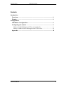
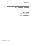
Display
Depending on the length of the LED Matrix display, from 4 up to 30
characters can be displayed at one-time. If the intended message is too long
for the number of displayable characters, the message will be scrolled
automatically through the display.
Figure: LED2-Matrix display, short version LED2_40
The desired messages can be either send from the CS121 devices in the network
or via RCCMD of any other network enabled devices.
LED2 User Manual
4
Generex GmbH
LED-Matrix Display
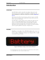
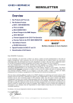
The LED Matrix is displaying the current text on the status site “LED Matrix”.
Figure: LED Display Status, Text and Buzzer Page
Use the button “Toggle Buzzer” to set the internal buzzer on or off.
The display will be refreshed all the time, so that the messages can always be monitored via
web-browser.
For example: The text above is generated by the configuration site “Automatic Mode”, cleft 2,
string: „UPS%n Output Frequency: %1.1Hz“.
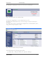
Figure: LED Matrix Display Settings & Templates
In the LED settings are the following options possible:
Display Type – LED2_40 or LED2_130 – depends on LED type
LED2 User Manual
5
Generex GmbH
LED-Matrix Display
UPS Type – 1 or 3-phase, depends on connected sender type (1 or 3-phase UPS).
Note: We recommend to use the LED2_130 for 3phase UPS, because the
LED2_40 is pre-configured for 1-phase UPS by default only.
Number of connected UPS – Number of connected UPS, this specifies how many
CS121/UPSMAN are permitted to send messages (10 at most)
Refresh Time in seconds – Definition of the term, how long a message will be
displayed until the next will be
Fonts – Default is SS7, more fonts are available
Display Mode – Hold or flash
You can add audible alarms for the standard events like Powerfail, Bypass Operation,
Overload, Overtemperature, General Alarm and Communication lost .
Optional: The GENEREX SM-Buzz can be connected to the AUX port of the LED Matrix.
The alarm buzzer events are predefined. For further configuration information, please take a
look into the CS121 User Manual
The default messages and measurement values of the automatic mode are displayed in the
LED templates. You can modify them if necessary.
Status - UPS%n Status: %1 (% is a variable, which can be replaced by the CS121
sender and its current measurement value)
Input Voltage - UPS%n Input: %1V %2V %3V (if 3-phase)
Input Frequency - UPS%n Input Frequency: %1.1Hz
Battery Voltage - UPS%n Battery Voltage: %1V
Autonomy Time - UPS%n Autonomy Time: %1 Min.
Output Voltage - UPS%n Output Voltage: %1V
Output Frequency - UPS%n Output Frequency: %1.1Hz
LED2 User Manual
6
Generex GmbH
LED-Matrix Display
The firmware version 3.88 (or higher) contains a new configuration menu, that provides the
option to configure the state in the desired language.
Figure: LED & UPS State Messages (italian)
During the sending of a message, the following will be registered in the log file of the
CS121/UPSMAN sender:
RCCMD is connecting to 192.168.202.101:6002 (RccmdConn01)
RCCMD finished to send. OK (RccmdConn01)
LED2 User Manual
7
Generex GmbH
LED-Matrix Display
Configuration
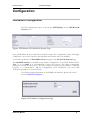
LED-Matrix Configuration
The first configuration step is to choose the LED Display in the UPS Model &
System menu.
Figure: LED-Matrix UPS Model & System Page
Note: LED Matrix devices built before 08/2012 require the configuration items „Exchange
COM Ports“ set as active. Devices after 08/2012 this function has to be disabled..
As second step follows the RCCMD Listener settings on the Network & Security Page.
The RCCMD Listener is enabled in the default configuration of the LED Matrix and its
Port is set on 6002. It is recommended to keep this settings. The other configuration
parameters should be adjusted to the local network settings using TELNET, a terminal
program or a web-browser. Add the configuration route 10.10.10.10 (via “route add
10.10.10.10 ip-address of your local host).
For further setting information of the SNMP web-interface, please take a look
into the CS121 User Manual
Figure: LED-Matrix Configuration Page
LED2 User Manual
8
Generex GmbH
LED-Matrix Display
Configuring the sender
Note: You have to decide between one of the following modes.
Do not connect senders in different modes to the same LED Matrix!
You can run the LED Matrix in Automatic Mode or either in the Manual Mode.
We want to explain subsequent, how to set up the CS121 or rather the UPSMAN
(as senders) and the LED Matrix. Every RCCMD sender (CS121, UPSMAN and
any other kind of licenzed RCCMD senders) is able to send messages to the LED
Matrix. Every RCCMD client is also able to send messages via scripting-language.
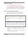
Mode 1: Send UPS State and Data automatically
In order to display the UPS status and measurement values in the LED Matrix,
you need to set up the following configuration in the CS121 Network &
Security configuration page of the web-interface. Note: These settings are for
the CS121/UPSMAN senders only and not for the LED Matrix!
Click the Enable LED Display Sender box
Enter a unique Number in the range from 0 to 9 in the field LED Display Sender
ID. This Number is used to identify this device on the LED-Matrix
Enter the IP Address of the LED-Matrix in the field LED Display Listener
Address
Note: Remember to click the Apply button to confirm your changes. After
all changes are done, click the Save Configuration Page and click Save, Exit
& Reboot.
In this mode all data and measurement values of the UPS, which got the LED
mode activated, will automatically displayed. For the use of the Automatic
Mode is a firmware of 3.80 or higher required.
LED2 User Manual
9
Generex GmbH
LED-Matrix Display
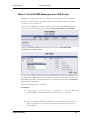
Mode 2: Send RCCMD Messages from UPS Events
Example: Configuring the CS121 to send event messages to the LED Matrix.
Set up the sender (CS121) manually with the text message and the accordant
syntax as you can see below.
If you want to display the autonomy time of the UPS on the LED Matrix, you
need to set up the following in the menu Events and Alarms / Powerfail:
Click the Add new job button and select the function Send RCCMD
Command to remote client.
Set up the ip-address of the destination (LED Matrix) and the port 6002 into the
job parameters. Note: 6003 is the default port, which is reserved for all the other
RCCMD commands. As described before, the 6002 port is the default Listener
port of the LED Matrix.
The command-line is the following:
Examples:
1. “ |UPSCMD|2000|Welcome to GENEREX " : The text „Welcome
to GENEREX“ will be displayed until an other text is received.
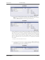
2. The configuration below will display the text „BATT“ directly and onetime in accordance to the selected circular button, after the UPS is in
Battery Mode.
LED2 User Manual
10
Generex GmbH
LED-Matrix Display
3. If you want to display further messages on the LED Matrix, click the
Apply button to commit the current job and return to the event overview.
Click the Add new job button and set up your desired job.
In the example above are the settings for the display of the variable #ATIME,
the balance time of the batteries, recorded. This time will be displayed with a
delay of 30 seconds in a 30 seconds interval. The balance time of the batteries
are the “autonomy time in minutes”. Please take a look into the Appendix
(page 14), where you will see the UPS standard variables. If you want to add a
text, e. g. a dimension unit, you can execute it, if you separate the command
with a blank:
|UPSCMD|2000|#ATIME Minutes
4. To send an all-clear message to cancel an alarm like Power restored after
a Powerfail, just select the event Power restored in the event overview
and record a suitable text like “Grid Okay”.
LED2 User Manual
11
Generex GmbH
LED-Matrix Display
Note: Remember to click the Apply button to commit your changes every
time. After all changes are done, click the Save & Exit and Reboot button in
the Save Configuration menu.
Tests: If the CS121 is connected to the UPS, the green LED is flashing and the
web-browser is displaying measurement values, tests can be started, like UPS in
battery mode or to send test-signals out of the Events & Alarms section of the
CS121/UPSMAN.
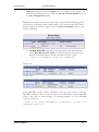
5. ALARM BUZZER: Switching the alarm buzzer at the LED Matrix, a
CS121 RCCMD execute signal is needed. Set up the destination (ipaddress of the LED Matrix) and the port 6002. Use the syntax:
“|AUX|3|1” to switch on, “|AUX|3|0 “ to switch off.
Buzzer ON:
Buzzer OFF:
Every RCCMD sender (CS121, UPSMAN and any other kind of licenzed
RCCMD senders) is able to send messages to the LED Matrix. Every RCCMD
client is also able to send messages via scripting-language. Use the RCCMD
syntax to switch off:
“rccmd -s -a <your LED MATRIX IP address> -p 6002 -se
"EXECUTE |AUX|1|0"
LED2 User Manual
12
Generex GmbH
LED-Matrix Display
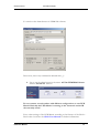
To switch on the alarm buzzer via UPSMAN software:
Please note, that every command is initiated with „|“
6. Try to test the alarm buzzer in the menu AUX & TEMPMAN Status
with the Switch On buttons.
Do not connect several senders with different configurations to one LED
Matrix! Basically the LED Matrix is running in the automatic mode OR
the manually mode!
Every other settings of the LED Matrix according to the features of the CS121 –
Please take a look into the CS121 User Manual for further information.
LED2 User Manual
13
Generex GmbH
LED-Matrix Display
Appendix
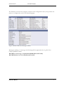
UPS Standard Variables
#STATUS
#INVOLT0
#INVOLT1
#INVOLT2
#INCURR
#BATTVOLT
#TEMPDEG
#AUTONOMTIME
#BATTCAP
#OUTPOWER0 (Last in %)
#OUTPOWER1
#OUTPOWER2
#INFREQ0
#INFREQ1
#INFREQ2
#OUTFREQ0
#OUTFREQ1
#OUTFREQ2
#SECONBAT
(Powerfail: seconds on battery)
#MANUFACTURER
#MODEL
(defined value)
#LOCATION
(defined value)
#ATTACHED_DEVICES (defined value)
#POWER
(defined value)
#LOAD
(defined value)
#HOLDTIME
(defined value)
#RECHARGETIME
(defined value)
#LOCALTIME
("dd.mm.yyyy hh:mm")
#DATE
("dd/mm/yyyy")
#TIME
("hh:mm")
#BATTINSTDATE ("dd.mm.yyyy")
#AGENTSOFTREV (Firmware Version)
#TEMP1 (SensorManager variables)
#TEMP2
#TEMP3
#TEMP4
#TEMP5
#TEMP6
#TEMP7
#TEMP8
LED2 User Manual
14
Generex GmbH
LED-Matrix Display
#SM2_ANALOG0 (SiteManager II variables)
#SM2_ANALOG1
#SM2_ANALOG2
#SM2_ANALOG3
#SM2_ANALOG4
#SM2_ANALOG5
#SM2_ANALOG6
#SM2_ANALOG7
All other variables depend of the type of UPS. ATTENTION!!! The manually display mode is
not provided for CS121 Budget adapters!
LED2 User Manual
15