1
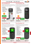
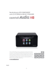
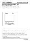
Instruction manual High voltage insulation resistance tester KEW3125A/3025A Contents 1. Safety warnings・・・・・・・・・・・・・・・・・・・・・・・・・・・・・・・・・・・・・・・・・ 1 2. Features ・・・・・・・・・・・・・・・・・・・・・・・・・・・・・・・・・・・・・・・・・・・・・・・ 5 3. Specification ・・・・・・・・・・・・・・・・・・・・・・・・・・・・・・・・・・・・・・・・・・・ 6 4. Instrument layout ・・・・・・・・・・・・・・・・・・・・・・・・・・・・・・・・・・・・・・10 4-1 Instrument layout ・・・・・・・・・・・・・・・・・・・・・・・・・・・・・・・・・・10 4-2 LCD display ・・・・・・・・・・・・・・・・・・・・・・・・・・・・・・・・・・・・・・・ 11 4-3 How to remove the Hard case ・・・・・・・・・・・・・・・・・・・・・・12 5. Getting started ・・・・・・・・・・・・・・・・・・・・・・・・・・・・・・・・・・・・・・・・13 5-1 Checking the battery voltage・ ・・・・・・・・・・・・・・・・・・・・・・・13 5-2 Connecting test leads ・・・・・・・・・・・・・・・・・・・・・・・・・・・・・・13 6. Measurement・・・・・・・・・・・・・・・・・・・・・・・・・・・・・・・・・・・・・・・・・・14 6-1 Mains disconnection check (Voltage measurement) ・・・14 6-2 Insulation resistance measurement ・・・・・・・・・・・・・・・・・・15 6-3 Continuous measurement ・・・・・・・・・・・・・・・・・・・・・・・・・・18 6-4 DAR/PI measurement・・・・・・・・・・・・・・・・・・・・・・・・・・・・・・18 6-5 Voltage characteristics at measuring terminal・・・・・・・・ 23 6-6 Use of Guard terminal ・・・・・・・・・・・・・・・・・・・・・・・・・・・・・ 23 6-7 Backlight function・・・・・・・・・・・・・・・・・・・・・・・・・・・・・・・・・・24 6-8 Auto-power-off function ・・・・・・・・・・・・・・・・・・・・・・・・・・・・24 7. Battery replacement ・・・・・・・・・・・・・・・・・・・・・・・・・・・・・・・・・・・ 25 8. Accessories ・・・・・・・・・・・・・・・・・・・・・・・・・・・・・・・・・・・・・・・・・・ 26 8-1 Metal parts for Line Probe, and replacement・・・・・・・・・ 26 8-2 How to use the adaptor for recorder ・・・・・・・・・・・・・・・・ 27 8-3 Line probe with alligator clip(optional accessory) ・・・・・ 28 9. Disposing the product ・・・・・・・・・・・・・・・・・・・・・・・・・・・・・・・・・ 29 1.Safety warnings ○This instrument has been designed, manufactured and tested according to IEC 61010: Safety requirements for Electronic Measuring apparatus, and delivered in the best condition after passing quality control tests. This instruction manual contains warnings and safety rules which must be observed by the user to ensure safe operation of the instrument and to maintain it in safe condition. Therefore, read through these operating instructions before using the instrument. # WARNING ● Read through and understand instructions contained in this manual before starting to use the instrument. ● Keep the manual at hand to enable quick reference whenever necessary. ● The instrument is to be used only in its intended applications. ● Understand and follow all the safety instructions contained in the manual. It is essential that the above instructions are adhered to. Failure to follow the above instructions may cause injury, instrument damage and/or damage to equipment under test. ○The symbol # indicated on the instrument means that the user must refer to the related parts in the manual for safe operation of the instrument. It is essential to read the instructions wherever the symbol # appears in the manual. # DANGER is reserved for conditions and actions that are likely to cause serious or fatal injury. # WARNING is reserved for conditions and actions that can cause serious or fatal injury. # CAUTION is reserved for conditions and actions that can cause injury or instrument damage. ̶ 1 ̶ # DANGER ● Never make measurements under the circumstances exceeding the designed measurement category and the rated voltage of the instrument and the test leads. ● Do not attempt to make measurements in the presence of flammable gasses. Otherwise, the use of the instrument may cause sparking, which can lead to an explosion. ● Never attempt to use the instrument if its surface or your hand is wet. ● Be careful not to short-circuit the power line with the metal part of the test leads when measuring a voltage. It may cause personal injury. ● Do not exceed the maximum allowable input of any measuring ranges. ● Do not press the Test button with test leads connected to the instrument. ● Never open the Battery compartment cover during a measurement. ● To prevent possible electrical shock, do not touch the circuit under test during an insulation resistance measurement or right after a measurement. # WARNING ● Never attempt to make any measurements if any abnormal conditions such as broken case and exposed metal parts are noted. ● Do not rotate the Range switch with the test leads connected to the equipment under test. ● Do not install substitute parts or make any modifications to the instrument. Return the instrument to your local KYORITSU distributor for repair or re-calibration. ● Do not try to replace the batteries if the surface of the instrument is wet. ● Insert the plug into the terminal firmly when using test leads. ● Ensure that the instrument is switched off before opening the Battery compartment cover for battery replacement. ̶ 2 ̶ # CAUTION ● Before starting a measurement, confirm that the Range switch is at an appropriate position. ● Set the Range switch to“OFF”position after use. Remove the batteries if the instrument is to be stored and will not be in use for a long period. ● Do not expose the instrument to direct sunlight, high temperatures and humidity or dew. ● Use a damp cloth with alcohol for cleaning the instrument and the areas around the measuring terminals. ● When this instrument is wet, please store it after it dries. ● The Voltage warning mark is being displayed during a measurement and it starts blinking when voltages 30V(DC/ AC) or more exist on the circuit under test. Symbols Danger of possible electric shock Instrument with double or reinforced insulation User must refer to the manual DC AC Earth terminal Crossed-out wheel bin symbol (according to WEEE Directive: 2002/96/EC) indicating that this electrical product may not be treated as household waste, but that it must be collected and treated separately. ̶ 3 ̶ ○ Measurement categories (Over-voltage categories) To ensure safe operation of measuring instruments, IEC 61010 establishes safety standards for various electrical environments, categorized as O to CAT I V, and called measurement categories. Higher-numbered categories correspond to electrical environments with greater momentary energy, so a measuring instrument designed for CAT III environments can endure greater momentary energy than one designed for CAT II. O : Circuits which are not directly connected to the mains power supply. CAT II : Electrical circuits of equipment connected to an AC electrical outlet by a power cord. CAT III : Primary electrical circuits of the equipment connected directly to the distribution panel, and feeders from the distribution panel to outlets. CAT IV : The circuit from the service drop to the service entrance, and to the power meter and primary overcurrent protection device (distribution panel). O: Device which is not directly connected to the mains power supply ̶ 4 ̶ 2. Features KEW3125A/3025A are high voltage insulation resistance testers with 5-range(3125A)/ 4-range(3025A) for measuring insulation resistance. ● Designed to meet the following safety standards: IEC 61010-1,-2-030 (CAT III 600V/CAT IV 300V Pollution degree 2) IEC 61010-031 (Requirements for hand-held probes) ● With auto-discharge function When an insulation resistance like a capacitive load is measured, electric charges stored in capacitive circuits are automatically discharged after the measurement. Discharge can be checked on the voltage monitor. ● Backlight function to facilitate working at dimly illuminated location or at nighttime work. ● Bar graph display ● Audible and visible LIVE circuit warning ● With Auto-power off function The instrument automatically will turn itself off if there is no function change or button press for 10 min to conserve battery power. ● Auto-measurement and display of PI (Polarization Index), DAR (Dielectric Absorption Ratio) ̶ 5 ̶ 3. Specification ● Applicable standards IEC 61010-1,-2-030 Measurement CAT III 600V Pollution degree2 Measurement CAT IV 300V Pollution degree2 IEC 61010-031 Standard for hand-held probes MODEL7165A(CAT IV 600V) MODEL7264(CAT IV 600V) MODEL7265(CAT IV 600V) * When KEW3125A/3025A and the test lead are combined and used together, whichever is lower category either of them belongs to is applied. IEC 61326-1,-2-2 EMC standard IEC 60529 IP40 EN 50581 RoHS Directive ● Measuring range and accuracy (Temperature, humidity: 23±5Cº, 45-75%RH) 【Insulation resistance tester】:KEW3125A/3025A Rated voltage Measuring Range Display range Open circuit Voltage 250V 0.0-100.0MΩ 500V 0.0-99.9MΩ 80-1000MΩ 1000V 0.0-99.9MΩ 80-999MΩ 0.80-2.00GΩ 2500V 0.0-99.9MΩ 80-999MΩ 0.80-9.99GΩ 8.0-100.0GΩ 0.0 ‒ 105.0MΩ 0.0-1050MΩ 0.0M-2.10GΩ 0.0M-105.0GΩ DC 250V +10%, -10% DC 500V +20%, -10% DC 1000V +20%, -0% 1mA or more, 1.2mA or less (at 1MΩ load) DC 2500V +20%, -0% 1mA or more, 1.2mA or less (at 2.5MΩ load) Rated Current Short-circuit Current Accuracy 1.5mA±0.5mA ±5%rdg±3dgt ̶ 6 ̶ * KEW3125A has an additional range. Rated voltage Measuring Range(*1) 5000V 80-1000GΩ 0.0-99.9MΩ 80-999MΩ 0.80-9.99GΩ 8.0-99.9GΩ Display range 0.0M-1200GΩ Open circuit Voltage DC 5000V Rated Current 1mA or more, 1.2mA or less (at 5MΩ load) Short-circuit Current 1.5mA±0.5mA Accuracy ±5%rdg±3dgt ±20% Voltage monitor for insulation resistance range KEW3125A: 30 - 6000V (resolution 10V): ±10%rdg±20V KEW3025A: 30 - 3000V (resolution 10V): ±10%rdg±20V This monitor is used to check whether electric charges stored on the equipment under test are discharged or not. The voltage value measured and displayed on the LCD is a reference value. Please note that the indicated value, when an external AC voltage is applied to the instrument, is not a correct value. 【Voltage measurement range】 Measuring range DC voltage AC voltage ±30 - ±600V 30 - 600V(50/60Hz) Resolution 1V Accuracy ±2%rdg±3dgt ̶ 7 ̶ ●Display: Liquid crystal display Insulation resistance range:(Max.1200 counts) VAC/DC range:(Max. 630counts) Bar graph: Max. 36points DAR/PI value: Max. 9.99 Time: Max. 99:59 ●Low battery warning: Battery symbol (in 4 levels) ●Overrange indication: “O L”ma rk a p p ea rs o n insulatio n resistance range. “Hi”mark appears on voltage range. ●Auto-ranging: Range shifts to upper range: 1000counts Range shifts to lower range: 80counts (Only on the insulation resistance range) ●Auto-power-off: The instrument will be powered off if there is no switch or button operation for 10 min. (This function does not work during a measurement.) ●Altitude: 2000m or less ●Temperature & humidity range(guaranteed accuracy): 23ºC±5ºC/Relative humidity 85% or less (no condensation) ●Operating temperature & humidity range: 0ºC to 40ºC/Relative humidity 85% or less (no condensation) ●Storage temperature & humidity range: -20ºC to +60ºC/Relative humidity 75% or less (no condensation) ●Overload protection: Insulation resistance range: AC1200V/10sec. Voltage range: AC720V/10sec. ●Withstand voltage: AC5160V(50/60Hz)/5sec. (Between electrical circuit and enclosure) ●Insulation resistance: 1000MΩ or more/ DC1000V (Between electrical circuit and enclosure) ●Dimension: 177(L)×226(W)×100(D)mm ●Weight: KEW3125A:approx. 1.9kg(battery included), KEW3025A:approx. 1.7kg(battery included) ●Power source: DC12V: LR14(Alkaline battery size C)x 8pcs ̶ 8 ̶ ●Current consumption (representative values at 12V of supply voltage) Range 250V 500V Output at short-circuit When rated current is outputted 1000V 2500V 5000V VAC/DC 200mA 3125A 350mA 400mA 500mA 750mA 900mA /0.25MΩ /0.5MΩ /1MΩ /2.5MΩ /5MΩ 3025A 250mA 300mA 350mA 500mA /0.25MΩ /0.5MΩ /1MΩ /2.5MΩ Output at open circuit 40mA 40mA Stand-by Backlight on 50mA 80mA − 110mA 150mA 25mA Increased by 40mA ●Measurement time: 3125A:approx. for 25hours *u nder a load of 10 0 MΩ on the Insulation resistance 5000V range. 3025A:approx. for 80hours *u nder a load of 10 0 MΩ on the Insulation resistance 2500V range. ●Accessories: Line probe: MODEL 7165A (Including MODEL8255 Straight type prod with molded parts) Earth cord: MODEL 7264 Guard cord: MODEL 7265 LR14(Alkaline battery size C)x 8pcs Instruction manual Hard Case: MODEL 9179 Pickel Type Prod: MODEL 8019 Straight Type Prod: MODEL 8254 ●Optional accessories: Adaptor for recorder:MODEL8302 Lin e p ro b e wit h alligato r clip: MODEL7168A Long Line probe with alligator clip (15m): MODEL7253 ̶ 9 ̶ 4. Instrument layout 4-1 Instrument layout 1 7 8 6 11 3 1 2 3 4 5 6 7 8 9 10 11 4 2 LCD display Range Switch Test button Back Light button DISP button Line Terminal Earth Terminal Guard Terminal Line Probe (red) Earth Cord (black) Guard Cord (green) ̶ 10 ̶ 5 10 9 4-2 LCD display 5 2 4 3 1 11 10 12 13 6 9 7 8 1 2 3 4 5 6 7 8 9 10 11 12 13 Insulation resistance Bar graph Voltage monitor Battery mark Voltage warning mark Timer display DAR mark PI mark DAR/PI value DC AC Minus display Unit ̶ 11 ̶ 4-3 How to remove the Hard case Hold the side surface of the terminal part, and gently pull the unit toward the front. ① Hold the side surface of the terminal part. ② Pull the unit toward the front. ̶ 12 ̶ 5. Getting started 5-1 Checking the battery voltage (1) Set the Range switch to any position other than“OFF”. (2) When the Battery mark shown at the upper left on the LCD is last one level , the batteries are almost exhausted. Replace the batteries with new ones to perform further measurements. The instrument operates properly even if under such a low battery level, and it may not affect on the accuracy. When the empty Battery mark appears, the battery voltage is below the lower limit of the operating voltage. So the accuracy cannot be guaranteed. Please refer to clause 7. Battery Replacement, for the battery replacement procedures. 5-2 Connecting test leads Insert the test lead firmly to the connector terminal on the instrument. Connect the Line Probe(red) to the Line terminal, the Earth Cord(black) to the Earth terminal and the Guard Cord(green) to the Guard terminal. A Guard cord connection may not be required, if there is no need to establish a guard. # DANGER ● If the Test button is pressed when the Range switch is at the insulation measurement positions, high voltage may be applied to the test leads and you may get an electric shock. ̶ 13 ̶ 6. Measurement 6-1 Mains disconnection check (Voltage measurement) # DANGER ● Never make measurements under the circumstances exceeding the designed measurement category and the rated voltage of the instrument and the test leads. ● When testing installations which have large current capacities, such as a power line, be sure to make measurement on the secondary side of the circuit breaker in order to avoid getting an electrical shock. ● Extra caution should be taken to minimize the possibilities of shorting the power line with the metal tip of test lead at voltage measurement. It may cause personal injury. ● The Battery cover must be closed and screwed before starting a measurement. ● Connect the Earth cord (black) to the Earth terminal of the circuit under test. Voltage can be measured by setting the Range switch on this instrument to“VAC/DC ”position. No need to press the Test button. This instrument is equipped with an AC/DC autodetection circuit and can measure DC voltage. During a DC voltage measurement, when applying a positive voltage to the Line Probe (red), positive values are displayed on the LCD. Be sure to turn off the circuit breaker of the circuit under test. (1) Connect the Earth Cord (black) to the earth side of the circuit under test and the Line Probe (red) to the line side respectively. (2) The voltage displayed on the LCD shall be “0V”. If it is not 0V, a voltage is applied on the circuit under test. Check the circuit under test again and turn off the circuit breaker. ̶ 14 ̶ 6-2 Insulation resistance measurement # DANGER ● Use a measuring apparatus, such as high voltage detector, and confirm that there is no electrical charge in the circuit under test. ● Wear a pair of insulated gloves for high voltage. ● If the Range switch is at the insulation resistance range and the Test button is being pressed down, high voltages are generated and applied to the test leads and the circuit under test continuously. Do not touch the circuit or the test leads. ● The Battery cover must be closed and screwed before starting a measurement. ● Never make measurement when thunder rumbling. ● Connect the Earth Cord (black) to the earth terminal of the circuit under test. ● When any modes other than“VOLT”is selected, live circuit warning symbol appears on the LCD and the audible warning activates if a voltage of 30V or higher is measured. KEW3125A/3025A don’t start a test, even the Test button is pressed down, if the measuring voltage is 160V or higher. Before starting a test, ensure that the equipment under test is disconnected from the mains supply and not energized in order to avoid possible electrical hazards. These instruments may start a test for energized electrical circuits if the measuring voltage is less than 160V. This instrument measures insulation resistances and check whether the insulations of electrical equipments or circuits are in good condition or not. So, please check the voltage that can be applied to the equipment under test before making a measurement. Note) ●The insulation resistance values of the equipments under test may not be stable, and the readings may be unstable. ●Bleep sound may be heard during an insulation resistance measurement, but it is not malfunction. ̶ 15 ̶ ●It takes time to measure a capacitive load. ●At insulation resistance measurement, positive (+) voltage is outputted from the Earth terminal and negative (-) voltage is outputted from the Line terminal. Connect the Earth cord to the Earth (ground) terminal. It is recommended to connect the positive(+) pole to the earth side when measuring insulation resistance against the ground or when a part of the equipment under test is earthed. With this connection, smaller measured value can be obtained comparing with other way round. (1) Check the voltage which can be applied to the circuit under test, and set the range switch to a desired insulation resistance range. (2) Connect the Earth cord (black) to the Earth terminal of the circuit under test. (3) Place the tip of the Line probe (red) to the circuit under test. Then press the“PRESS TO TEST”button. The buzzer sounds intermittently during a measurement when a range other than 250/500V is selected. (4) The measured value will be displayed on the LCD, and it is kept displayed after the measurement. # Caution Always turn off the Breaker for the circuit under test. ̶ 16 ̶ (5) This instrument has an auto-discharge function. With the test leads connected to the circuit under test, release the Test button to discharge capacitances in the circuit after test. Confirm that the indication on the voltage monitor becomes“0V”. # DANGER ● Do not touch the circuit under test immediately after testing. Capacitances stored in the circuit may cause electric shock. ● Leave the test leads connected to the circuit and never touch the circuit until a discharge is complete. Auto-discharge function This is a function to release the capacitances stored in the circuit under test automatically after test. The voltage monitor shows the discharge condition. This function will be disabled by disconnecting the test leads 2sec. or more before discharge is complete. (6) Set the Range switch to“OFF”position, and disconnect the test leads from the instrument. ̶ 17 ̶ Principle of Insulation Resistance Measurement A resistance value can be obtained by applying a certain high voltage to the resistor (insulation resistance) and measuring the flowing current. Resistance value = Voltage / Current (RX = V / I) 6-3 Continuous Measurement Press and turn the Test button clockwise and lock the button to measure insulation resistances continuously. Turn the button counterclockwise and set it to the initial position after a measurement. # DANGER ● Be extremely careful not to get electric shock as a high voltage is present on the tip of the test leads continuously. 6-4 DAR/PI measurement 1. PI - Polarization index This is to check a temporal increase of leakage currents flowing on insulations and to confirm leakage currents aren’t increased as time passes. PI is usually determined by the insulation resistances measured 1 min and 10 min after a measurement is started. PI is dependent on the shape of insulations and influenced by moisture absorption, therefore, a check of PI is important ̶ 18 ̶ to diagnosis the insulation of cables. Insulation resistance (10 min after a start of test) PI = Insulation resistance (1 min after a start of test) PI 4 or more 4-2 2.0 - 1.0 1.0 or less Criteria Best Good Warning Bad 2. DAR - Dielectric Absorption Ratio DAR measurement is almost the same to PI measurement in a sense that they test the time course of insulation. The only difference is that DAR measurement can get result faster than the other. Insulation resistance (1 min after a start of test) DAR = Insulation resistance (15 or 30 sec min after a start of test)*1 DAR 1.4 or more 1.25 - 1.0 1.0 or less Criteria Best Good Bad Note1: DAR time is selectable: 15 or 30 sec. How to select: 1) Keep the DISP button pressed down and rotate the Range switch to power on KEW3125A/3025A. (DAR mark starts blinking.) 2) Press the DISP button to switch 15 sec and 30 sec displayed at the lower left on the LCD. Select a desired one. 3) Then power off the instrument. The selected DAR time will be saved and not be cleared even when the instrument is powered off. To confirm the selected time, follow the step (1). ̶ 19 ̶ 3. How to measure DAR/ PI DAR and PI are automatically measured during a normal continuous measurement of insulation resistances. Set the Range switch to any desired range and measure the test object continuously. - 1 min after a start of continuous measurement: LCD shows DAR value. - 10 min after a start of continuous measurement: LCD shows PI value. When DAR/PI values are displayed as“no”: DAR and PI values are determined by Methods 1. and 2. as described above, therefore, they are displayed as “no” when the measured insulation resistances fall under any of the following cases. *1 measured value is “0.0MΩ” *2 measured value is “OL” “ * OL”is displayed when the measured value exceeds the upper limit of the measuring range at each insulation resistance range. Range Upper limit 250V 105.0MΩ 500V 1050MΩ 1000V 2.10GΩ 2500V 105.0GΩ 5000V 1200GΩ ̶ 20 ̶ 4. Display examples of DAR/ PI values The DAR/PI values are displayed as follows during a measurement. (1) Start of test No DAR/PI value, “---” is displayed. (2) 1 min after the start of test DAR value is displayed. (3) 10 min after the start of test PI value is displayed. Press the DISP button to switch DAR and PI values. 5. How to review the measured DAR/ PI values Press the DISP button after a measurement. The measured results are then displayed in the following sequence. If a measurement ends earlier than the intervals described in below (2), (3) or (4), nothing will be displayed and returns to the initial state (1). ̶ 21 ̶ (1) End of test (B) (C) (A) (A) Time when a test ends (B) Value measured at the end of test (resistance value) (C) DAR or PI value (2) Results at 15 or 30 sec after a start of test (B) (A) (C) (A) Elapsed time (15 or 30 sec) (B) Value measured 15 or 30 sec after a start of test. (resistance value, output voltage) (C) DAR value (3) Results at 1 min after a start of test (B) (A) (C) (A) Elapsed time (1 min) (B) Value measured 1 min after a start of test. (resistance value, output voltage) (C) DAR value (4) Results at 10 min after a start of test (B) (A) (C) Return to (1) (A) Elapsed time (10 min) (B) Value measured 10 min after a start of test. (resistance value, output voltage) (C) PI value ̶ 22 ̶ 6-5 Voltage characteristics at measuring terminal KEW3125A/3025A Output characteristics 6000 5000V range Output voltage (V) 5000 4000 3000 2500V range 2000 1000V range 500V range 250V range 1000 0 0.1 MΩ 1 MΩ 10 MΩ 100 MΩ 1000 MΩ 10 GΩ Insulation resistance 100 GΩ 1000 GΩ 6-6 Use of Guard terminal When measuring the insulation resistance of a cable, leakage current flowing on the surface of cable jacket and the current flowing inside the insulator are mixed and may cause error in insulation resistance value. In order to prevent such error, wind a conductive wire around the point where leakage current flows. Then connect it to the Guard terminal. This is to move out the surface leakage resistance of the cable insulation to measure only the volume resistance of insulator. Make sure to use the Guard cord supplied with this instrument to connect the instrument to Guard terminal. ̶ 23 ̶ * It is possible to move out the surface leakage resistance of the insulation and measure only the volume resistance by using the Guard terminal. This is helpful when performing tests in humid air. 6-7 Backlight function This function to facilitate working at dimly illuminated location or at nighttime work. Press the backlight button when the range switch is at any position other than“OFF”. The backlight will light up for about 60 sec, and then turn off automatically. (The light will not turn off automatically during a measurement.) 6-8 Auto-power-off function The instrument will automatically turn itself off if there is no function change or button press for about 10 min. To return to the normal mode, turn the Range switch to OFF position once, and then to any desired position. (This function does not work during a measurement or while the instrument is giving an audible and visible live circuit warning.) ̶ 24 ̶ 7.Battery replacement # DANGER ● Do not open the Battery compartment cover if the surface of the instrument is wet. ● Never open the Battery compartment cover during a measurement. ● To avoid possible electric shock, disconnect the test leads and Power Adaptor from the instrument before replacing batteries. After replacing batteries, make sure to tighten up the screw for the Battery compartment cover. # CAUTION ● Do not mix new and old batteries. ● Make sure to install batteries in correct polarity as marked inside. (1) Set the Range switch to “OFF” position, and disconnect the test leads from the instrument. (2) Loosen the Battery compartment cover-fixing screws, and remove the Battery compartment cover. Remove all eight batteries and replace them with new ones. (3) After replacing batteries, be sure to tighten up the screw for the Battery compartment cover. SCREW Make sure to install batteries in correct polarity as marked inside. ̶ 25 ̶ 8.Accessories 8-1 Metal parts for Line Probe, and replacement # DANGER Attach MODEL8255 to the test leads to use the instrument in CAT II or higher environments. MODEL8254 and 8019 have exposed large metal parts, therefore, they may short circuit the equipment under test and also may damage the equipments under test, cause fire or pose fatal or serious injuries to the users. (1) Tip metal parts MODEL8255: Standard Prod (straight type, with molded parts) MODEL8254: Straight Type Prod MODEL8019: Pickel Type Prod To be used to hook the instrument. (2) Replacement Turn the Line probe counterclockwise to remove the attached tip metal. Put the tip metal you want to use to the hexagon socket and turn it clockwise together with the tip of probe, and tighten up the screws. MODEL8255 Male Screw Hexagon Socket MODEL8254 MODEL8019 ̶ 26 ̶ 8-2 How to use the adaptor for recorder MODEL8302 is an adaptor for a recorder (option) for output current measurement. Connect it as shown in the below figure. Output is DC1mV when current of 1μA is flowing. To shield or Earth - To recorder + ̶ 27 ̶ 8-3 Line probe with alligator clip(optional accessory) (1) MODEL7168A Line probe with alligator clip (2) MODEL7253 Long Line probe with alligator clip (15m) ̶ 28 ̶ 9. Disposing the Product Waste Electrical and Electronic Equipment (WEEE), Directive 2002/96/EC This Product complies with the WEEE Directive (2002/96/ EC) marking requirement. The affixed product label (see below) indicates that you must not discard this electrical/electronic product in domestic household waste. Product Category With reference to the equipment types in the WEEE directive Annex 1, this product is classified as a“Monitoring and Control instrumentation”product. Disposing lead-storage batteries When you throw away the batteries, be sure to cover their positive and negative terminals and always observe local laws and regulations. Insufficient insulation of the terminals may cause explosion or fire because electrical energies remain in lead-storage batteries after use. ̶ 29 ̶ DISTRIBUTOR Kyoritsu reserves the rights to change specifications or designs described in this manual without notice and without obligations. 02-15 92-2189