1
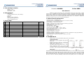
5. The package contains
-
Ammeter АМ4080
АМ4080 - 1 pcs.
Mounting kit - 1 pcs.
User manual - 1 pcs.
User Manual
6. Manufacturer
АМ4080 is digital measurement, fully programmable device from series 4080. It measures
current up to 10 AAC/ADC and can measure other current by connecting external shunt resistor or
current sensor. AM4080 can be directly connected to current transformer with maximum secondary
current of 10Aac. The device can be purchased with potential-free contacts for remote signalization if
measured current goes out of certain programmable limits (option “R”). AM4080 is designed to be
mounted on boards in control rooms of electrical substations.
Gineers Ltd
7 "Iskarsko shausse” blvd, TCE, building 4
1528 Sofia
Bulgaria
tel./fax (+359-2): 9758105
URL: http://www.gineers.com
e-mail: [email protected]
1. Main technical parameters
7. Fault Table
#
Date
Fault
Series 4080
Description of the repairs
Signatu
re
-
measured current – alternating/direct
max input current - 10 АAC/АDC (overload up to 10 times for 100ms)
power supply – 55-270 VAC (80-390 VDC)
input resistance – max 0.010 Ω for 5 А
display – super bright red, 4 digits, view area 75х22mm, purple filter
measurement error - <1.2 % rdg + 2 digit
single measurement cycle - < 1 s
menu protection – yes/no
user menu access code: 1342/..........
potential-free contacts number – 3 N.O. – yes/no
max. contact voltage/current – 0.5 ADC @ 220 VDC
power consumption - max 3 W
work ambient temperature - 0÷50 °C
storage temperature - -50÷+90 °C
влажност на въздуха - 40÷90 %
dimensions (H/W/D) –48/96/85 mm (w/o plugs attached) и 48/96/95 mm (w/t plugs attached)
mounting hole (H/W) – 43/90 mm, centered
IP protection class – IP52 front (mounted on board), IP31 back
weight – 220 g
2. AM4080 Work
AM4080 starts working immediately after power up as described:
-
-
Initialization Mode
Decimal point of least significant digit lights for
about 0.2s
Display shows moving “Gineers” - for about 3s.
Display goes blank, then shows the nominal
input current – for about 1.5s
The device enters normal work mode – shows
instant measured current, one of the LEDs
(low/normal/high) is lit, and if the device is with
“R”-option – one of the relay contacts is closed.
Work mode
The device shows the instant measured current (related to the primary side of the current
transformer, if one used) and continuously monitors and signals if its value is within certain programmed
limits (low/hi) via front panel LEDs and relay contacts. If the value is outside these limits, the display
blinks with frequency about 2-3Hz (blinking can be turned off via user menu). The device alarms for
value outside limits after time, set as number of consecutive measurements out of the limits. It is made
this way in order to avoid the possibility of false short-time signaling. Then, for entering back into
normal limits, the current must be within the limits plus programmed hysteresis value, as shown on
fig.1. There is no time delay when returning to “within limits” mode.
AM4080 programming
AM4080 can be programmed via user menu. The user can enter in the menu by pressing the
“OK” key when the device is in normal working mode. IT IS FORBIDDEN to press any key when the
device is in initialization mode! If AM4080 is with option “С” (АМ4080C), the menu requires user code ;
the display shows ‘uSEr’, until “OK” key is depressed. After that the display shows “codE” and the device
waits for four-digit user code to be entered. If the entered code is valid, then the user is allowed to the
menu; and if the code is invalid, the user cannot have access to the menu and the device returns back
to normal working mode. Entering the code is basically four-digit parameter edit (see below). If the
device is without option “C”, user code is not required and the user is allowed to the menu, the display
shows the first parameter in the menu (diSP).
-
-
-
User menu parameters:
nominal (primary) current (diSp)
This is the value the display shows at nominal input current, i.e. this parameter along with the
next (decimal point position) determine the nominal input current when current transformer is
used (set '1000' if the connection is direct).
decimal point position (dP)
low level (Lo)
Below this level of input current AM4080 signals for value below limits – with LED and relay
high level (Hi)
Over this level of input current AM4080 signals for value above limits – with LED and relay
display blinking when value is outside programmed limits (bLin)
turns on/off display blinking if the value is outside programmed limits
hysteresis (HYSt)
This is the difference between current entering and exiting “value outside limits” mode ad
signalization
signalization delay (rdEL)
This is the number of consecutive measurements before the device signals that the current is
outside programmed limits
When entering user menu the display shows “diSP” – the first parameter in the menu. Other
parameters can be chosen by pressing ‘Ò’ key, and editing the chosen parameter can be done by
pressing ‘ОК’ key. Exiting the menu can be done only if parameter is not edited at the moment
(i.e. the user can exit the menu only when choosing parameter to edit) by pressing and holding ‘Ò’
key and briefly pressing ‘OK’ key when 'Ò’ is pressed. After exiting the menu AM4080 continues to
work normally.
IMPORTANT: When the device is in the menu, it does not measure input value and
therefore does not alarm if the value is – or it is not – within the programmed limits. All
of the signals remain as they were prior entering the menu!
Parameter editing – if the parameter is chosen by ‘Ò’ key, with ‘OK’ key the user can edit
the parameter. If the parameter has several digits to be entered, with both the keys the digits are
edited one by one: after entering “parameter edit” mode the display shows the current value of the
parameters and the most significant digit is blinking. Blinking of the digit means that it is the current
edited digit, and pressing ‘Ò’ key increments it with 1. After reaching ‘9’ incrementing the digit resets its
value to '0'. Pressing ‘OK’ key confirms the value of this digit and goes to the next digit, which now
blinks. After confirmation of the last digit the parameter is saved and the user goes back to the menu to
select another parameter to edit.
If the parameter to edit has several values or options, then with ‘Ò’ key the user can go round
all the options/values and when selects the correct one, confirms it with the ‘OK’ key and goes back to
the menu.
This table shows the factory default settings and limits for all the parameters in the menu:
Parameter(submenu)
Nominal primary current
Decimal point position
High level
Low level
Display blinking
Hysteresis
Relay delay
Display
Limits
0000-9999
1.000-1000
0000-9999
0000-9999
on/oFF
0000-0099
0000-0099
diSP
dP
Hi
Lo
bLin
HYSt
rdEL
3.
Mounting
and
electrical connection
АМ4080 should be mounted
on board with opening 43x90mm with
mounting kit, supplied with the device.
All connections must be made with
isolated cables with cross sectional area
of 0.75mm2÷2.5mm2. The connections
are shown on the next figure:
Default value
1000
10.00
1200
0800
On
0010
0008
POWER
INPUT
55-250Vac
80-350Vdc
0-10AAC/ADC
1
2
C1
3
1
2
3
HI NORM LO
NC
1
2
C2
NC
3
4
NC
5
6
C3
С1 ‘Power'
No
Description
1, 3
Power supply
2
Not used
Input current'
No
Description
1
Input current, minus /shunt input minus
2
Не се използва
3
Input current, plus /shunt input plus
С3 'Relays'
No
Description
1,2
NO-contact “high value”
3,4
NO-contact “normal value” (value within limits)
5,6
NO-contact “low value”
IMPORTANT: Only qualified personnel, familiar with safety instructions and this user manual
should be allowed to work with AM4080!
4. Warranty
The warranty of the device is limited to two years from the date of sale. If the device shows
any defect or malfunctions during that period, the manufacturer is obligated to repair the device in its
own service for manufacturer's expense, or, if the repair is impossible, to replace the device with new
one. The transportation costs to the manufacturer's service are due to the client. The warranty voids if
this manual instructions are not met, warranty seals are removed or the device was opened by
unauthorized by the manufacturer personnel.
Serial number:....................
Date of sale:........................
Signature:...........................