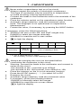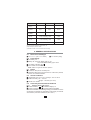
1
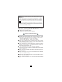
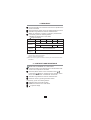
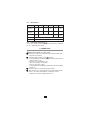
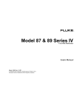
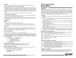
Digital Multimeter Model C.A 5230 MULTIMETER - 0 + ZER O HOL D MAX mV 10 20 30 Mk n u FA Hz 40 MIN MAX RAN GE HOL D Hz ZERO V V OFF mA 10A 600V COM CAT III 10A ! 500m FUSE A D 10A FUSEmax D C.A RMS ENGLISH MULT 5230 IM E T ER User manual 1 Warning ! Please refer to the User’s Manual before using the instrument. In this User’s Manual, the instructions preceded by the above symbol, should they not be carried out as shown, can result in a physical accident or damage the instrument and the installations. This device is protected by a double insulation or by a reinforced insulation. No linking is required from the protection earth terminal to ensure the electrical security. Thank you for purchasing a C.A 5230 RMS Multimeter. To get the best service from this instrument : read this user manual carefully, respect the safety precautions detailed. SAFETY PRECAUTIONS Respect the value and the type of fuses or there is risk of deterioration of the instrument and invalidation of the warranty. - Fuse 0.5A HBC (500V min - 10kA - 6.3 x 32mm) - Fuse 12A HBC (600V min - 300kA - 10.3 x 38mm) Never use on voltage to earth circuits above 600V, with a voltage surge category of over III, that is to say, fixed industrial and domestic installations (ref. IEC 664-1). To be used indoors in environments with a maximum pollution degree of 2 (ref. IEC 664-1), a temperature between 0 and 50°C and relative humidity below 70%. Use accessories which conform to safety standards (IEC 1010-2-031), with a minimum voltage of 600V and a voltage surge of category III. Never open the multimeter case before disconnecting from any electrical source. Never connect up to a circuit to be measured if the multimeter case is not closed correctly. Before any measurements are taken, ensure the leads and switch are in the correct positions. Never measure resistances on a circuit with the power switched on. 2 CONTENTS 12345678910 11 12 - Presentation ............................................................................. 3 Description ............................................................................... 4 DC and AC voltage (V) ............................................................ 5 Frequency (Hz) ....................................................................... 6 Continuity and resistance (Ω/ ) ......................................... 6 Diode test ( ) ........................................................................ 7 Capacitance ( ) ................................................................... 8 DC and AC current (A and mA) ............................................... 8 General specifications ............................................................ 9 To order (accessories) ........................................................ 10 Warranty ............................................................................... 10 Maintenance ......................................................................... 10 Technical and Sales Assistance ........................................... 11 1 - PRESENTATION The C.A 5230 multimeter is designed for the daily needs of professionals in electricity. - true rms measurement (RMS) - digital 4000 counts and 42 segment bargraph - automatic or manual range selection - auto off after 30 minutes without action on a control or function - possibility of permanent operation (see HOLD) Various measurement accessories broaden the scope of application or provide the multimeter with new functions. See the list of accessories and references on the “To Order” page (Documentation upon request). Note : Always use accessories suitable for the voltage and the voltage surge category of the circuit to be measured (as per IEC 1010). 3 2 - DESCRIPTION LIQUID CRYSTAL DISPLAY 4000 measurement counts - height of digits 0.5" (12mm) Rate: 2 measurements / second Bargraph with 42 segments / Rate: 20 measurements / second Note: the bargraph is not operational on frequency and capacitance measurements Automatic display of all the symbols for commands, ranges and functions Use battery indication : + - Low battery indication : - the 4 on the left flashes - bargraph totally lit plus arrow CONTROL BUTTONS ... / ~ and Ω / To change from AC (~) to DC ( ... ) and reverse, on ammeter function. To change from continuity test to resistance measurement Ω and inverse, on ohmmeter function. Note: Automatic selection of AC and when switched on. HOLD and ZERO To freeze the display on the last measurement (HOLD). On capacitancemeter function , zero reset by press without releasing. Permanent operation: possibility of suppressing auto off, by pressing this button without releasing before operating the switch from the OFF position. The return to the OFF position cancels permanent operation. MIN - MAX To successively display the min or max values. The instrument then changes to manual range selection. HOLD is also displayed. Min acquisition time 500 ms. Note: The user can keep the min/max values in memory if you press the HOLD button, PRIOR to disconnecting the test leads. RANGE Range selection: to change from automatic mode to manual mode, by prolonged press on this button. Note: - automatic mode is selected when the instrument is switched on. - this button also selects the sensitivity for the Hz frequency meter function To switch on and off the display backlighting. Note: Auto off after 1 minute. 4 FUNCTION SELECTOR SWITCH OFF Off position V~ V ... DC voltages up to 600V Hz Frequencies of voltages up to 400kHz Ω AC voltages up to 600V in rms value Continuity sound test for a resistance R ≤ 40Ω, and measurements of resistances up to 40MΩ Note: The continuity test is selected automatically when the instrument is switched on. Diode test. Measurement of the voltage of the junction in forward direction Capacitances up to 40µF mA Current ranges up to 400mAAC/DC (via the + terminal) A 10AAC/DC current ranges (via the 10A terminal) TERMINALS Ø 4mm safety terminals COM: common, black +: red 10A: red lead for the 10AAC/DC ranges 3 - DC AND AC VOLTAGE Connect the leads to the multimeter and connect it in parallel to the circuit to be tested. Place the selector switch on the voltmeter function VAC/DC Automatic selection of the range: read the value measured. Freeze the value by pressing the HOLD button. If necessary, press the following buttons: RANGE to select the ranges manually MIN-MAX to read the min or max values to light the display V AC/DC 400mV (1) 4V 40V 400V 600V (2) Digital resolution 0.1mV 1mV 10mV 100mV 1V 10mV 100mV 1V 10V 100V 100MΩ 10MΩ Bargraph resolution Impedance Accuracy on DC Accuracy on AC Permitted overload 9.1MΩ ± 0.25% of Reading ±1ct ± 1.5% R ±5cts ± 1% of Reading ±3cts 600Vrms and 1000V peak (1) Accessible by the RANGE button. Min measurement : 20mV (2) Crest factor FC ≤ 3 5 4 - FREQUENCY Connect the leads to the multimeter and connect in parallel to the circuit to be tested. Place the selector switch on the Hz voltage frequency function. Automatic range selection: read the measured value Note: The bargraph is inactive on frequency measurement If necessary, press the following buttons: - MIN/MAX to read the min or max values to light the display Hz 100Hz 1kHz 10kHz 100kHz (2) 400kHz Resolution 0.01Hz 0.1Hz 1Hz 10Hz 100Hz ± 8cts ± 20cts ± 0.1% of Reading Accuracy ± 10cts Permitted overload ± 4cts 500V rms and 900V peak Operating range (1) 4V to 600V (1) The RANGE button for this function selects the triggering threshold : - 10mV for 100Hz, 1kHz and 10kHz ranges - 400mV for 100kHz and 400kHz ranges (2) Note : If the frequency applied is 99.99kHz, the decimal point oscillates between 9.999kHz and 99.99kHz. 5 - CONTINUITY AND RESISTANCE Never test a resistance on a live circuit Connect the leads to the multimeter and to the terminals of the circuit or the component to be tested. Ω Place the selector switch on the ohmmeter function Press the Ω / button to change from the continuity sound test to the measurement of resistances and reverse. Automatic range selection: read the measured value Freeze the value, by pressing the HOLD button. If necessary, press the following buttons: RANGE to select the range manually MIN/MAX to read the min or max values to light the display 6 5-1 Resistances Ω 400Ω 4kΩ 40kΩ 400kΩ 4MΩ 40MΩ Digital resolution 0.1Ω 1Ω 10Ω 100Ω 1kΩ 10kΩ Bargraph resolution 10Ω 100Ω 1kΩ 10kΩ 100kΩ 1MΩ ± 1% R ± 1.5% R ±4cts ±4cts Accuracy ± 1% R ± 4cts ± 0.5% of Reading ±3cts Voltage on ≤ 0.4 VDC Protection 500Vrms and 750V peak 5-2 Continuity sound test On the 400Ω range, emission of a continuous beep for a resistance R ≤ 40Ω. Response time: 100ms 6 - DIODE TEST Never test a diode on a live circuit Connect the leads to the multimeter and to the terminals of the component to be tested. Place the selector switch on the function: - in forward direction the display gives the value of the junction in volts (resolution 1mV) - accuracy: ±1% of Reading ± 2cts - open circuit voltage: 3.2V typical - short circuit current: 0.6mA - in reverse direction the display indicates the open circuit voltage, around 4V. Freeze the value, by pressing the HOLD button. With this function, it is possible to test, besides classic diodes, LED’s or any other semiconductor in which the junction corresponds to a direct voltage less than 3V. 7 7 - CAPACITANCE ♦ ♦ ♦ ♦ Never make a capacitance test on a live circuit Always respect the polarity of electrolytic condensers. This type of condenser may be sensitive to temperature, so avoid touching it during measurement. Connect the leads to the multimeter and to the terminals of the condenser. Place the selector switch on the capacitance meter function Automatic range selection: read the measured value Note: The bargraph is not operational on capacitance Measurement Freeze the value, if necessary, by pressing the HOLD button If necessary, press the following buttons: ♦ ZERO to set zero on the 4nF and 40nF ranges only ♦ RANGE to select the ranges manually ♦ MIN/MAX to read the min or max values to light the display ♦ 4nF 40nF 400nF 4µF Resolution 1pF 10pF 100pF 1nF Accuracy ±2% R ±150cts Protection (1) 40µF 10nF ±2% of reading ± 8cts 500V mns 750 peak (1) For a capacitance C> 20µF the accuracy is ±5% of the reading ± 8cts ♦ ♦ ♦ ♦ ♦ Always de-energize the circuit to be tested before connecting the multimeter to the circuit Warning: connect the leads to the multimeter and connect in series to the circuit -the red lead to the + terminal up to 400mA -the red lead to the 10A terminal, from 400mA to 10A Place the selector on the A or mA ammeter function Press the AC/DC button (... / ~) to select AC or DC Energize the circuit Automatic range selection: read the measured value If necessary, press the following buttons -RANGE to manually select the ranges -MIN/MAX to read the min or max values - to light the display 8 AAC/DC 40mA 400mA 10A (1) Voltage drop (2) 450mV 650mV 400mV Digital resolution 10µA 100µA 10mA Bargraph resolution 1mA 10mA 1A Accuracy on DC ± 0.8% of Reading ± 2cts ±1.2% R ± 4cts ± 1.2% of Reading ± 4cts ± 1.5% R ± 5cts Fuse 0.5A HBC Fuse 12A HBC Accuracy on AC (3) Protection (4) (1) Crest factor FC ≤ 3 (2) Voltage drop at the terminals for 40mA, 400mA, 10A (3) Use on frequency: 40Hz to 1000Hz (4) Permitted overloads: 12A for 30 seconds for the 10A range 9 - GENERAL SPECIFICATIONS 9-1 Dimensions and Weight 2.5 x 7 x 1.7 " (64 x 177 x 42mm) 9-2 12.3 ounces (350g) Power Supply One battery 9V Battery life: 300h with battery type 6 F 22 500 h with alkaline battery type 6 LF22 Low battery indication: Auto off after 30 minutes Note: Switch on again via the OFF position. + - 9.3 Buzzer Continuous beep for the continuity test Intermittent beep each time the switch or buttons are pressed, and for the overload indication. 9-4 Climatic conditions Temperature: use: 0°C to +50°C / storage : -20°C to +60°C Relative humidity: use: ≤ 70% RH storage: ≤ 90% RH (up to 45°C) Altitude: use <2000m 9-5 Conformity with International Standards 9-5-1 Electrical Safety (IEC 1010-1) Double insulation: Installation category: III Degree of pollution: 2 Assigned voltage: 600VRMS Note: This multimeter, of overvoltage category III satisfies the severe requirements of reliability and availability corresponding to industrial and domestic permanent installations (IEC 664-1). 9 9-5-2 Electromagnetic Compatibility: Conforms to CE Emission (EN 50081-1) Immunity (EN 50082-1) 9-5-3 Mechanical protection Degree of watertightness (IEC 529): protection index IP 40 10 - TO ORDER Use the designations and references below. C.A 5230 .................................................................... Cat. #2116.76 Sold with shockproof case, a pair of leads with probes attached, a 9V battery and this user’s manual Accessories AC current probe model MN 251 (200AAC) ............ Cat. #2115.77 AC current probe model MD 303 (500AAC) ............ Cat. #1201.21 AC current probe model SR 652 (1000AAC) .......... Cat. #2113.46 AC/DC MicroProbe model K110 (from 100µAAC/DC to 300mAAC / 450mADC) ............... Cat. #2111.73 AC/DC current probe model MR410 (400AAC / 600ADC) ..................................................... Cat. #1200.70 AmpFLEX model 1000-24-1-1 (1000AAC) ............. Cat. #2112.39 Replacement leads .................................................. Cat. #2118.66 Soft carrying case .................................................. Cat. #2118.65 Replacement shockproof case ............................... Cat. #2980.15 Fuse set of 10, 0.5A ............................................... Cat. #2970.28 Fuse set of 10, 12A ................................................ Cat. #2970.21 11 - WARRANTY Our guarantee is applicable for three years after the date on which the equipment is made available (copy available on request). 12 - MAINTENANCE For maintenance, use only specified spare parts. The manufacturer will not be held responsible for any accident occurring following a repair done other than by its factory or approved repairers. 12-1 Replacing the battery and the fuses The multimeter must be disconnected from any electrical source. Place the selector switch on the “OFF” position. Unscrew the tool release screws and remove the lower half of the case. 10 Replace the dead battery by a 9V battery (6F22 or 6LF22) Replace the defective fuses respecting their value and their type : - Fuse 0.5A HBC (500V - 10kA - min 6.3 x 32mm) - Fuse 12A HBC (600V min - 300kA - 10.3 x 38mm) 12-2 Storage If the multimeter is not to be used for a period of 60 days or more, remove the battery and store separately. 12-3 Cleaning The multimeter must be disconnected from any electrical source. To clean the case, use a cloth slightly moistened with soapy water. Rinse with a damp cloth. Then, dry rapidly with a cloth or in a hot air stream. 12-4 Repair and calibration To guarantee that your instrument complies with the factory specifications, we recommend that the Model C.A 5230 be submitted to our factory service center at one-year intervals for recalibration, or as required by other standards. For instrument repair and/or calibration, please call our factory, tollfree, at (800) 945-AEMC (800-945-2362): CHAUVIN ARNOUX, Inc. d.b.a. AEMC Instruments 15 Faraday Drive Dover, NH 03820 USA Tel : (800) 954-2362 (603) 749-6434 Fax : (603) 742-2346 (Or contact your authorized distributor) Costs for repair, standard calibration, and calibration traceable to N.I.S.T. are available upon request. Overseas customers must receive written authorization before returning any instrument. 12-5 Technical and Sales Assistance If you are experiencing any technical problems, or require any assistance with the proper use or application of this instrument, please call our technical hotline: CHAUVIN ARNOUX, Inc. d.b.a. AEMC Instruments 200 Foxborough Blvd. Foxborough, MA 02111 USA Tel : (800) 343-1391 (508) 698-2115 Fax : (508) 698-2118 www.aemc.com 11