1
Appendix C
MC-III™ WP Flow Analyzer
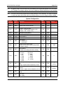
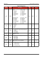
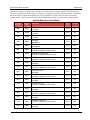
Input Configuration
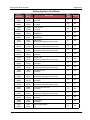
Register
(Decimal)
Register
(Hex)
Data
Type
Access
2051
0803
Calibration Factor [9]*
(pulses per configured factor unit)
FP
R/W
1.00
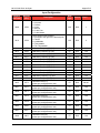
2053
0805
Calibration Factor [10]*
(pulses per configured factor unit)
FP
R/W
1.00
2055
0807
Calibration Factor [11]*
(pulses per configured factor unit)
FP
R/W
1.00
2057
0809
Calibration Factor [12]*
(pulses per configured factor unit)
FP
R/W
1.00
2059
080B
Standard Measurement Correction Factor
(to be configured by software only)
FP
RO
1.00
2061
080D
Low Flow Rate Cut-Off Threshold
(in terms of configured flow rate units)
FP
R/W
1.00
Description
Default
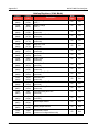
*Calibration frequencies and calibration factors are associated in pairs—i.e., Calibration Frequency [1] and
Calibration Factor [1]— and must be sorted in ascending order, based on calibration frequency values, prior
to writing the values to the instrument. Therefore, Calibration Frequency [1] should be the smallest of all
calibration frequencies.
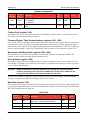
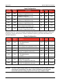
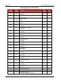
Output Configuration
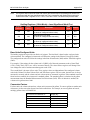
Register
(Decimal)
Register
(Hex)
4000
0FA0
Pulse Output Source
0 = Test Mode/Disabled
1 = Enabled
U16
R/W
0
4001
0FA1
Pulse Output Duration
(time is register value multiplied by 10 ms)
U16
R/W
10
(100 mS)
4002
0FA2
Pulse Output Decimal Point Location
U16
R/W
2
4003
0FA3
Pulse Output Scale Factor
(in terms of configured volume units)
FP
R/W
1.00
4005
0FA5
Analog Output Source
0 = Test Mode/Disabled
1 = Enabled
U16
R/W
0
4006
0FA6
Analog Output Decimal Point Location
U16
R/W
2
4007
0FA7
Analog Output Low Value
(in terms of configured flow rate units)
FP
R/W
0.00
4009
0FA9
Analog Output High Value
(in terms of configured flow rate units)
FP
R/W
1700.00
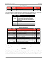
Important
C-8
Description
Data
Type
Access
Default
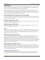
Two sets of 16-bit holding registers are provided (starting at 17001 and 8000). The “8000”
set displayed in parentheses in the table on page C-9 should be used with master
devices that require the holding registers to be in the range of 40000 to 49999.