1
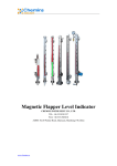
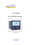
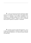
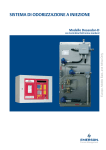
PHG-200 Series PH Transmitter
User Manual
PHG-201/202/203
YANTAI CHEMINS INSTRUMENT CO., LTD.
TEL: +86 535 8381357 FAX: +86 535 2945018
Website: www.chemins-tech.com
ADDR: No.68 Puzhao Road, Development Zone, Zhaoyuan, Shandong, China
Index
PHG‐200/ORP‐200 Series PH/ORP Transmitter User Manual (PHG‐201/202/203,ORP‐201/202) ........................................... 3 1. Typical applications ............................................................................................................................................... 3 2. Instrument characteristics..................................................................................................................................... 3 3. Product shape ....................................................................................................................................................... 3 4. Technical Specifications ......................................................................................................................................... 4 5. Installation instruction .......................................................................................................................................... 6 6. Configuration and settings .................................................................................................................................. 10 7. Maintenance ....................................................................................................................................................... 11 8. Packing list and accessories ................................................................................................................................. 12 9. Quality Assurance ............................................................................................................................................... 13 RS485 (Modbus/RTU) protocol ........................................................................................................................................... 13 www.chemins‐tech.com 2 / 15 PHG‐200/ORP‐200 Series PH/ORP Transmitter User Manual (PHG‐201/202/203,ORP‐201/202) 1. Typical applications
z
PHG-201: For PH on line measurement of swimming pool, aquatic farming, flower greenhouses, soilless
cultivation and etc, very cost efficient.
z
PHG-202: For PH on line measurement of waste water treatment, pure water, drinking water, surface water,
water supply, industrial sewage, cost efficient for basic industrial application.
z
PHG-203: For PH on line measurement of acid / alkali / salt solution, chemical reaction process, industrial
manufacturing process, can satisfy most of industrial application requirement.
2. Instrument characteristics
z
Multiple signal output is optional: 4-20mA(2 wire analog), 0-2V(analog), Rs485(Modbus/RTU, digital).
z
Easy connect to PLC, industrial computer, controller, data logger or touch screen for online monitor and
control.
z
Dual high-impedance differential amplifier, strong anti interference, fast response.
z
Patented pH probe, inner reference solution is promote by at least 100KPa pressure, extremely slow exudation.
So that the potential is very stable long-termly, and the lifetime of the reference electrode several times than
normal industrial probe.
z
The probe use gold plate VP header for plug connection. Threaded fastening, very easy to replace the probe.
z
Easy mounting. The 3/4” NPT thread is easy for pipe and tank mounting. The probe can be also separated with
the display header, connect by cable.
z
IP65 protection level.
3. Product shape
As to PHG-202 / 203, the middle one output analog signal, the right one output digital signal.
PHG-202 and PHG-203 have the same shape like the right 2, just internal sensor, circuit and software are different.
www.chemins‐tech.com 3 / 15 PHG-201
PHG-202 / PHG-203
4. Technical Specifications
PHG-201
PHG-202
PHG-203
4-20mA (2 wire);
Output signal
0-2V(option);
(All isolated)
Rs485(Modbus/RTU) (Option)
www.chemins‐tech.com 4 / 15 LED model: 4 bits LED display. Just display PH value.
LCD model: show pH value and temperature.
Display
2 button for operation (LED model)
3 buttons for operation (LCD model)
Operation
Calibration
2 point calibration.
Protection
IP65
Scale
0~14pH
Resolution
0.01pH
±0.05pH
Accuracy
3/4" NPT thread
Thread
Auto
PT1000
temperature
(PT100 or other NTC resistor are optional)
compensation
24VDC / 220VAC / 110VAC
24VDC
24VDC
PHE-200 combined glass pH
PHE-300 high performance
electrode.
combined glass pH electrode.
Power supply
Combined glass pH electrode.
PHE-100 or 3rd part 120mm
Electrode
electrode.
3.0KCl electrolyte, re-fillable,
3.0KCl Gel electrolyte, can't
long lifespan.
be re-filled.
0.1MPa pressured(default);
Electrolyte
Temperature
0~65℃
0~80℃
3.0KCl electrolyte, re-fillable,
long lifespan.
0.1MPa / 0.4MPa / 0.6MPa
pressured (Optional);
0~80℃
(0~130℃ is optional)
Pressure: <0.1MPa
Atmosphere pressure.
Atmosphere pressure.
(0.6MPa and even higher pressure
is optional)
Pressure
Reference
POM fiber salt bridge
Ceramic salt bridge
Ceramic salt bridge
Case
NYLON
NYLON
PPS
About 1 year.
About 1.5 year.
About 1.5 ~ 2 year.
Estimated
lifespan of
electrode
www.chemins‐tech.com 5 / 15 5. Installation instruction
Wiring
Other installation
www.chemins‐tech.com 6 / 15 Sanitary model
www.chemins‐tech.com 7 / 15 www.chemins‐tech.com 8 / 15 High pressure model
www.chemins‐tech.com 9 / 15 6. Configuration and settings
A. Calibration of PH transmitter
The transmitter can use US/NIST(4.01,7.00,10.01) and DIN(4.00,6.86,9.18) buffer solution for calibration. Below
context take pH 4.00, 6.86, 9.18 standard buffer solution (value in 25℃) as example.
Please note that after calibration in one kind of solution and before calibrate in another solution, we must use the
latter solution to clean the probe, otherwise it will introduce a lot of test error.
Zero calibration
Power on the transmitter, put the electrode into the buffer solution (6.86pH). Screen displays the current pH, the
transmitter output is 12mA (4-20mA). Please be note the displayed pH value had been compensated with the
medium temperature. To eliminate the error, adjusting the positioning potentiometer. (Tune of "O" in the circuit
potentiometer clockwise to increase, counterclockwise to decrease).
Slope calibration
Power on the transmitter, put the electrode into the buffer solution (4.00pH as first). The screen shows the current
measured pH value (this value is modified through the zero calibration). After the measured pH value is stable, the
transmitter output is 4.01 × 1.142 +4 = 8.58mA (4-20mA). To eliminate the error by adjusting the slope of the
potentiometer. (The "S" in the tone circuit on the potentiometer).
Put the electrode into the buffer solution (9.18pH). After the measured pH value is stable, the transmitter output
should be 9.18 × 1.142 +4 = 14.48mA (4 - 20 mA). To eliminate the error by adjusting the slope of the
potentiometer. (The "S" in the tone circuit on the potentiometer).
B. Calibration of ORP transmitter
Please note that after calibration in one kind of solution and before calibrate in another solution, we must use the
latter solution to clean the probe, otherwise it will introduce a lot of test error.
Zero calibration
Power on the transmitter, put the electrode into the buffer solution. Screen displays the current mV value. To
eliminate the error, adjusting the positioning potentiometer. (Tune of "O" in the circuit potentiometer clockwise to
increase, counterclockwise to decrease).
Slope calibration
Power on the transmitter, put the electrode into another buffer solution. The screen shows the current measured mV
value. After the measured mV value is stable, eliminate the error by adjusting the slope of the potentiometer. (The
"S" in the tone circuit on the potentiometer).
Calibrate the zero and slope point several times to ensure better accuracy.
www.chemins‐tech.com 10 / 15 C. Take into use
After take out the instrument from the box, check if there is any damage, leakage and loosening part.(It’s normal
that there is salt crystallization phenomenon near the reference salt bridge outside of the glass electrode).
After wiring is completed, tightening the screws of the junction box to ensure a good seal. (Serious moisture will
cause the output to be abnormal.)
Placed the probe in clean water, the displayed value should be about 7 pH. Due to the transport process, air bubbles
will be accumulated inside of bulb of the electrode, it will cause abnormal measurement result. At this point, lift the
sensor to be upright, hand tapping the sensor until can’t see the bubbles in the probe. Add few acid to the clean
water, the pH value should be obviously lower, it means the sensor become normal. Do not take the sensor into use
immediately, please soak it for more than 24 hours. So that the imbalance potential will be reduce, and it can be
take into use after re-calibration.
7. Maintenance
Periodic inspection of the instrument should be based on media situation. If the media situation is good, then
inspection can be taken every six months. In scaling or polluted media, inspection should be took every month or
every week, even if the sensor is equipped with automatic cleaning device.
The bottom of the transmitter junction boxes is the reference solution slot, it contact with media through the salt
bridge. If the sensor is with pressure compensation device, should be noted that the pressure indication can not be
lower than the medium pressure, to prevent media back flow which will cause pollution to the reference electrode.
In this case, periodic pneumatic compression is needed.
Why must soak the pH electrode before take into use?
The PH bulb is a special glass membrane. There is a thin layer of hydrated gel layer in the glass membrane surface.
After fully and enough soak, a stable H+ layers will be formed on the membrane surface. If soaking does not fully
and enough, the response value will be unstable and drift during measurement. 24 hours is enough when soaked in
3Mol KCL solution.
The main reason of electrode error and how to handle.
Stable reference system is the key for the stable and long life of the electrode. Following reason will significantly
affect the pH electrode performance: The Cl- ion loss on the liquid junction of the reference; pollution; membrane
blocking. This problem can only be resolved by re-calibrate the electrode.
However, even after good calibration, the on line measurement may not be accurate too. If the media pressure is
greater than the reference electrolyte pressure inside the electrode, it will result in reverse osmosis. Reverse
osmosis will pollute the electrode reference system seriously, it will result in inaccurate result, and even electrode
scrap.
To avoid this problem effectively? Our company take following innovative design for the pH sensor:
¾
Filling pressure: the inner pressure make the reference solution is always positive direction outward
penetration to avoid contamination.
¾
Increase the capacity of reference system: to ensure that longer oozing time.
www.chemins‐tech.com 11 / 15 ¾
Reduce the amount of exudation: to ensure a longer oozing time
¾
Dual high-impedance measurement circuit: to ensure a reliable reference signal when the reference electrode
oozing slowly.
The relation between temperature and the PH value of the standard buffer solution
Temperature
pH value
℃
0.05M
0.025M
Potassium hydrogen phthalate Mixed phosphate
10
4.00
6.92
15
4.00
6.90
20
4.00
6.88
25
4.00
6.86
30
4.01
6.85
35
4.02
6.84
40
4.03
6.84
45
4.04
6.83
50
4.06
6.83
0.01M
Borax
9.33
9.28
9.23
9.18
9.14
9.10
9.07
9.04
9.02
Glass electrode is a consumable, the life cycle is about one year or so. The lifetime of the electrode based on
maintenance situation and the measured medium. In bad media or poor maintenance, the lifetime of the electrode
will be greatly reduced. Therefore, the electrode need to be replaced with new one.
Electrode replacement is easy as below picture:
8. Packing list and accessories
Packing list:
www.chemins‐tech.com 12 / 15 z
Instrument which include sensor.
z
A set of 3 bags of pH buffer, can be used to make standard buffer solution. pH value is 4.00, 6.86, 9.18 (in
25℃).
z
1 copy of user manual.
z
Thredolet (optional)
pH buffer is a consumable item, not in warranty.
9. Quality Assurance
This product is one-year warranty, from date of delivery. Product warranty does not cover damage caused by
improper usage. If need repair, please return and take the freight cost. Good packaging is required to avoid
transportation damage.
Glass electrode lifespan is related to usage environment, not in warranty issue.
RS485 (Modbus/RTU) protocol This meter/transmitter adopts ModBus-RTU communication protocol. The communication baud rate is 9600bps.
1.
Word Format: 1 Start bit +8 bit Data + 1 Even Parity Check bit +1 Stop bit, totally11bit.
2.
Frame Structure: Address Code (1Byte) + Function Code (1Byte) +
Code (2Byte).
Data segment (n Byte,) + CRC Check
The transmission of message frame start at least a pause interval of 3.5 bytes’ time. The entire message frame
must be transmitted as a continuous stream. If there is more than pause of 3.5 bytes’ time, the receiving device
will treat the transmission of the current message frame is end, and assume that the next received byte is the
start of the new frame byte.
Address Code: The address of slave device, ranging from 0 to 255. It can be set through the menu, the factory
default is 6.
Function Code: The standard ModBus communication protocol defined function codes 1-127. This meter /
transmitter only use the 03 (read the data of register) function code to read the data of register.
Data segment: The host use function code 03 to inform the slave send back the specified length data from the
specified register (Message frame contains the length of the start address of the register, and the length of data
of the register). The returned data from the slave includes the data length and data content. The address, length
and data are all hexadecimal, the high byte first and the low byte last.
CRC Check Code: hexadecimal,
3.
low byte first and high byte last.
Communication example (the slave address is 6):
3.1 Reading main measured values (the start address of register is 0x0101)
www.chemins‐tech.com 13 / 15 The sent frame of Host device
Address
Function
Start address
Quantity
Code
Code
of the register
of the register
06
CRC16
High
Low
High
Low
Low
High
01
01
00
02
95
80
03
The response frame of Slave device
Address
Function
Length
Data
Code
Code
of data byte
06
03
04
XX
XX
CRC16
00
0X
XX
XX
3.2 Reading temperature value (the start address of register is 0X0103)
The sent frame of Host Device
Address
Function
Start address
Quantity
Code
Code
of the register
of the register
06
CRC16
High
Low
High
Low
Low
High
01
03
00
02
34
40
03
The response frame of Slave Device
Address
Function
Length
Code
Code
of data byte
06
03
04
Data
XX
XX
CRC16
00
01
XX
XX
Note: The host should read the values of two registers each time. The returned 4 bytes from the slave is as complete
instrument data. The first 2 bytes representing the data (in the form of complement, the highest bit is sign bit), the
last 2 bytes indicating the position of decimal point or the number of decimal (the decimal of temperature is fixed
to 1, means temperature shows like 20.1).
www.chemins‐tech.com 14 / 15 Thanks for your support to our products!
YANTAI CHEMINS INSTRUMENT CO., LTD.
TEL: +86 535 8381357 FAX: +86 535 2945018
Website: www.chemins-tech.com
ADDR: No.68 Puzhao Road, Development Zone, Zhaoyuan, Shandong, China
www.chemins‐tech.com 15 / 15