1
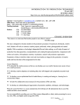
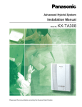
 310C Digital Video Apartment Intercom System USER MANUAL For RJ-45 Digital Video System

Thanksforchoosingourhomeintelligentproducts.
Toassurethebestperformances,pleasereadthismanualcarefully!
I. Brief Introductions (Features)
This Digital Video Apartment Intercom System is composed with Outdoor Panel,
Indoor Monitor, Manage center and accessories. Multi-function and Luxury
OutdoorPanelscouldsuitfordifferentBuildingsandcommunityrequirements.
Main features: 1. RJ-45InterfacesEasyWiring,Maximumusers9999.
2. Highbrightnessdigitaltubedisplay.
3. UsercansetindividualUnlockingcode.
4. ICandIDcardAccessControloptional.
5. SoftcodingRoomNumber(From0000to9999).
6. Audio&Videocompatible(2wayintercom,RJ-45Interface).
7. HighResolutioncameraLens,AutosenseNightVision.
8. SupportmultipleOutdoorPanelsApartment/Buildingsystems.

II. Outlook & Introduction III. The Operation of Door Station 1.
CALL INDOOR PHONES PressRoomNumber(3or4Digits)onDoorStationtocallIndoorUser(s).
Press“#”toCancelOperation,andRedial.
BidirectionalIntercomwhenUser(s)Pickup.UserscouldPress“UNLOCK”button
toReleaseDoorLock.Visitor(s)couldpress“#”toendconversation.

2.
CALL MANAGE CENTER (Optional) Visitor(s)couldalsoPress“0000”toCallManageCenterforIntercom&Unlock.

3.
INDIVIDUAL PASSWORDS UNLOCK Input “*”, Display “----”, Enter Four Digits Room Number (Add “0”if not
enoughFourdigits),Display“----”.
InputFourDigitsIndividualPasswords,thenDoorLockwouldbeAutoReleased.
IfPasswordsisnotcorrect,Display“ERROL”.

4.
RFID/ IC Access Control (Optional) UsingAuthorizedIDorICCards,BrushattheRFIDWindowSensorArea.
Whenhearing“Di,Di”,DoorLockwouldbeAutomaticallyReleased.
5.
CONTROL PARAMETERS ADJUST Pleasereferthefollowingpart<<OutdoorStationParametersSetting>>

IV. FLOOR DECODER SETTING OurLatestVideoFloorDecoderisUseRJ-45 InterfaceforConnection.

(Picture 1) INSTRUCTIONS Thereare8Pinsindicatedwith1,2,4,8,16,32,A,B(AsabovePicture1).Whenthe
TerminalisShortConnectedbyPinCap,thenitstandsfortheNumberaccordingly.
1. Thepins(1,2,4,8,16and32)standforFloorNumber.ReferBelowtable.
PIN
Number
Stands
1
1
2
2
4
4
8
8
16
16
32
32
A
ROOM
RANGE
B
NULL
Floor Number: Add all the Short Connected Pins Indicated Number together.

DetailedFloorNumbercoding,pleaserefertothe<<FloorDecoderCodeTable>>

DEFAULT ROOM NUMBER CALCULATION Under DEFAULT CODING MODE, the Full Room Number is Four Digits. The First
twoDigitsstandforFloorNumber,the3rdand4thDigitsstandforRoomNumber.
WhenPinAisnotShortConnected,theRoomNumberfrom01to04.
IfthePinAisShortConnected,theRoomNumberfrom05to08.
UnderthisCODINGMODE,ThePhysicalAddressRangeis0101~6304.
For example, in the below Picture 1.
ThePhysicalAddressFloorNumberis50.(2+16+32=50)
2.
ThePhysicalAddressRoomN.O.fromInterface1~4are01~04accordingly.
3.
TheFullPhysicalRoomN.O.fromRJ-45Interfaces1~4are5001~5004.
4.
IfthePINAisShortConnected,thenFullRoomN.O.is5004~5008.

V. FREE CODING OF ROOM NUMBER (INSTRUCTION) UnderFREECODINGMode,PhysicaladdressRoomNumbercouldbechangedto
otherrequiredRoomNumberfreely.(NotallowRoomNumberrepeat)

Change Physical address Room N.O. to Free Room N.O. Instruction (TakePhysicalRoomN.O.“5002” change to “6666”forexample) 1.
UnderStandbyState,press“**”,theOutdoorstationwillshow“1234”.
2.
ThenInput8digitsManagementPasswords(FactoryDefault20021268).
3.
WithaLongsoundof“Di”,theOutdoorstationwillshow“1--7”.
4.
Press “4”, Display First Physical Address“01JI”. (“01”stands for Physical
Address1stFloor,“J1”standsforPhysicalAddress1stRoom).
5.
Enter3 Digits(2FloorN.O.and1RoomN.O.)ofthePhysicalRoomNumber
needtobechanged.  (HereEnter“502”,thenpress“*”,display“50J2”).
6.
EntertheRequiredRoomNumber.(HereInput“6666”.Display“50J3”).
7. ThenPress“#”tosavechangesandEXIT.
Atlast,PhysicalRoomN.O.“5002”hasbeensuccessfullychangedto“6666”.
Now,whenCall“6666”,the50hFloor,andthe2ndRoomwouldringing.
Any other Physical Room Numbers could be changed freely the same way.
VI. Outdoor Station Parameters Setting Parameters Setting ForSafetyconsideration,ManagementPasswords(FactoryDefault20021268)are
requiredtoputinbeforeEnterParametersSettingMode.

Enter Parameters Setting Model 1. UnderStandbyState,press“**”,theOutdoorstationwillshow“1234”.
2.
ThenInput8digitsManagementPasswords(FactoryDefault20021268).
3.
WithaLongsoundof“Di”,theOutdoorstationwillshow“1--7”.
Parameters Setting Instructions COMMANDS NUMBER CODE INSTRUCTION Remarks 1
XXX
SetBuildingNumber
ThreeDigitsNumber
ChangeManagement
EightDigits,Default
Passwords
Passwordsis20021268
2
XXXXXXXX
3
XXXX
4
XXJY
5
Y--N
SetIndividualUnlock
Passwords
FourDigitsNumber
FreeCodingRoom
XX standsforFloorN.O.
Number
YstandsforRoomN.O.
InitializePhysical
Y standsforYES
AddressRoomN.O.
N standsforNO
6
7
NULL
1--2
NULLFunction
RoomN.O.Mode
NullFunction
1 StandsforNumber
2StandsforCharacters
Remarks: After setting successfully, press“#”Key to Save and Exit.
※ COMMANDS One: Set Building Number
Ifthereareseveralbuildingsinsamecommunity,BuildingsarerequiredtobeSet3
DigitsBuildingNumbertodistinguish.(Rangefrom001to999)
When under setting mode “1--7”, press “1”, LCD display“111”. Enter the 3
DigitsBuildingRoomneedtobeset.Display“GOOD”,meanssuccessfully.

※ COMMANDS Two: Change Management Passwords
TheFactoryDefaultPasswordsare“20021268”.
When under setting mode “1--7”, press “2”, LCD firstly display “NE1”, and
then display “1234”. Enter Eight Digits New Management Passwords; display
“NE2”,then“1234”.Re-entertheNewpasswordsagaintoconfirm.
Iftwotimesenterthesamepasswords,display“GOOD”,meanssuccessfully.

※ COMMANDS Three: Set Individual Unlock Passwords
ThissystemsupportIndividualPasswordUnlockfromOutdoorPanel.
Whenundersettingmode“1--7”,press“3”,WhenLCDdisplays“----”,Enter
the4DigitsRoomNumberneedpasswords,firstdisplay“NE1”,then“----”.
Inputthe4DigitsIndividualUnlockpasswords,firstdisplay“NE2”,then“----”.
Re-enterthePasswordsagain.Whendisplay“GOOD”,meanssuccessfully.

※ COMMANDS Four: Free Coding Room Number
This apartment system, Room Number could be free Coding to any Four Digits
RoomNumber(Range0001to9999).NotallowRoomNumberrepeat.

※ COMMANDS Five: Initialize Physical Address Room N.O.
After Free Coding Room Number, if Customers need to return all the changed
RoomNumberstoPreviousPhysicalAddressRoomNumber.
When under setting mode “1--7”, press “5”, firstly display “CLN”, then
display“Y--N”.  Enter“*”,display“----”then“GOOD”.

※ COMMANDS Seven: Room N.O. Mode
FactorydefaultisPureDigitsmode,whichisstronglyrecommended.
Whenundersettingmode“1--7”,press“7”,LCDdisplay“1--2”.
Enter“1”,standsforPureDigitsRoomNumbermode.
Enter“2”,standsforMixedCharactersRoomNumbermode.
Remind: Under any Setting steps, press “#”will back, and End up settings.
VII. Special Part for Remote Control Instruction EnterProgrammingstate:Press1234F2
IncreaseCard:Press1F2,Greenlightflushcontinuously,andnowswipeRFIDkeys
onebyonetoaddnewusers.
DeleteCard:  Press3F2,Redlightflushcontinuously,andnowswipeRFIDkeysone
byonetodeleteusers.
AddRFIDKeyN.O.:Press0XXXXXXXXXX.(XXXXXXXXXXstandsRFIDKeyN.O.)
DeleteRFIDKeyN.O.:Press2XXXXXXXXXX.(XXXXXXXXXXstandsRFIDKeyN.O.)
DoorNormallyOpen(NO):  Press5F2,thensaveandexitsystemautomatically.
DoorNormallyClose(NC):  Press6F2,thensaveandexitsystemautomatically.
DoorOpenOnetime:  Press7F2,thendooropenandexitsystemautomatically.
ChangePasswords:  Press8XXXXF2.(XXXXstandsfornew4Digitspasswords)
EXITSystem:  PressEXITButtonornoOperationsin10Seconds


VIII. System Wiring Diagram Below Wiring diagram is a Single System. If need Network system, welcome to contact our Agents, Distributors or Sales for more details. Whole system could use RJ-45 Interfaces to connect up, CAT-6 Cable.