1
Puritan Bennett
Achieva® Ventilators
with Flow Acceleration and Apnea Back Up
Clinician’s Manual
©Copyright 2003 Nellcor Puritan Bennett Inc., Pleasanton CA, U.S.A. All rights reserved.
Puritan Bennett is a registered trademark and Achieva is a trademark of Nellcor Puritan Bennett Inc. For more information,
contact your Puritan Bennett Representative.
Achieva Ventilator Clinician’s Manual
Introduction . . . . . . . . . . . . . . . . . . . . . . . . . . . . . . . . . . . . . . . . . . . . . . . . . . . . . . 1-1
Chapters ................................................................................................... 1-2
Additional information............................................................................... 1-4
Conventions .............................................................................................. 1-4
Symbols and their definitions ..................................................................... 1-5
Overview. . . . . . . . . . . . . . . . . . . . . . . . . . . . . . . . . . . . . . . . . . . . . . . . . . . . . . . . . 2-1
Features.................................................................................................... 2-1
Electromagnetic interference...................................................................... 2-2
Software Errors.......................................................................................... 2-3
General warnings and cautions ................................................................. 2-4
If the ventilator fails................................................................................... 2-4
Description . . . . . . . . . . . . . . . . . . . . . . . . . . . . . . . . . . . . . . . . . . . . . . . . . . . . . . . 3-1
Intended use ............................................................................................. 3-1
Contra-indications..................................................................................... 3-1
Front panels .............................................................................................. 3-2
Top panel.................................................................................................. 3-2
Controls and display.................................................................................. 3-5
Back and sides ........................................................................................ 3-10
Inside door label ..................................................................................... 3-12
Top label................................................................................................. 3-12
Side label................................................................................................ 3-13
Agency symbols label ............................................................................. 3-13
Back panel label...................................................................................... 3-14
Accessories.............................................................................................. 3-15
Set up . . . . . . . . . . . . . . . . . . . . . . . . . . . . . . . . . . . . . . . . . . . . . . . . . . . . . . . . . . . 4-1
Unpacking ................................................................................................ 4-1
Inspection ................................................................................................. 4-2
Accessory checklist .................................................................................... 4-3
Power ....................................................................................................... 4-4
AC Power .................................................................................................. 4-4
External Battery 24 Volt DC ....................................................................... 4-5
External Battery 12 Volt DC ....................................................................... 4-6
Battery Performance .................................................................................. 4-7
Testing the Batteries .................................................................................. 4-8
External battery precautions....................................................................... 4-9
Internal Battery 24 Volt DC ........................................................................ 4-9
Attaching the patient circuit ..................................................................... 4-12
Attaching oxygen..................................................................................... 4-15
Short term humidification ........................................................................ 4-16
Extended Use .......................................................................................... 4-17
Connecting to a nurse call system ............................................................ 4-19
November 2003
i
Achieva Ventilator Clinician’s Manual
Operating the controls............................................................................. 4-21
User self test ........................................................................................... 4-23
Setting the low pressure alarm................................................................. 4-26
Operation. . . . . . . . . . . . . . . . . . . . . . . . . . . . . . . . . . . . . . . . . . . . . . . . . . . . . . . . 5-1
Starting the ventilator ................................................................................ 5-1
Stopping the ventilator .............................................................................. 5-2
Sensitivity and adjustment ......................................................................... 5-3
Display of settings ..................................................................................... 5-3
Changing modes....................................................................................... 5-3
Flow trigger............................................................................................... 5-4
Pressure trigger ......................................................................................... 5-5
Altitude setting .......................................................................................... 5-6
Assist/Control mode, volume breaths......................................................... 5-7
Limiting inspiratory flow (Flow Acceleration) ............................................... 5-8
Expiratory sensitivity .................................................................................. 5-9
Assist/Control mode, pressure-controlled................................................. 5-10
SIMV mode with pressure support ............................................................ 5-11
SIMV mode with CPAP ............................................................................. 5-12
Spontaneous mode with pressure support (Flow acceleration) .................. 5-13
Spontaneous mode with CPAP (Achieva PS and Achieva PSO2) ................ 5-15
Ventilation modes and apnea .................................................................. 5-16
Monthly safety check ............................................................................... 5-17
Verifying Alarm Functions ........................................................................ 5-18
Menu selections ...................................................................................... 5-22
User self test ........................................................................................... 5-22
Ventilating hours ..................................................................................... 5-22
Pressure trigger ....................................................................................... 5-23
Date and time ......................................................................................... 5-23
What the patient and caregiver must know .............................................. 5-25
Alarms and alerts . . . . . . . . . . . . . . . . . . . . . . . . . . . . . . . . . . . . . . . . . . . . . . . . . 6-1
Alarm sounds ............................................................................................ 6-3
Latching and non-latching ......................................................................... 6-4
Presilence.................................................................................................. 6-5
Resetting alarms........................................................................................ 6-5
Alarm conditions ...................................................................................... 6-6
Troubleshooting . . . . . . . . . . . . . . . . . . . . . . . . . . . . . . . . . . . . . . . . . . . . . . . . . . . 7-1
Troubleshooting chart................................................................................ 7-1
Maintenance . . . . . . . . . . . . . . . . . . . . . . . . . . . . . . . . . . . . . . . . . . . . . . . . . . . . . 8-1
Cleaning and sterilization .......................................................................... 8-1
Ventilator surface ...................................................................................... 8-2
ii
November 2003
Achieva Ventilator Clinician’s Manual
Flatpak filter.............................................................................................. 8-2
Changing the fuse..................................................................................... 8-4
Periodic maintenance ................................................................................ 8-6
Ventilator data . . . . . . . . . . . . . . . . . . . . . . . . . . . . . . . . . . . . . . . . . . . . . . . . . . . A-1
Printing reports from the ventilator............................................................. A-1
Local data transfer..................................................................................... A-3
Download procedure................................................................................. A-4
Remote data transfer ................................................................................. A-6
Glossary. . . . . . . . . . . . . . . . . . . . . . . . . . . . . . . . . . . . . . . . . . . . . . . . . . . . . . . . . B-1
Resources. . . . . . . . . . . . . . . . . . . . . . . . . . . . . . . . . . . . . . . . . . . . . . . . . . . . . . . . .C-1
Bibliography.............................................................................................. C-1
Organizations ........................................................................................... C-1
Theory of operation . . . . . . . . . . . . . . . . . . . . . . . . . . . . . . . . . . . . . . . . . . . . . . . . D-1
Pneumatic diagram ...................................................................................D-1
Breaths and ventilation modes...................................................................D-4
Specifications. . . . . . . . . . . . . . . . . . . . . . . . . . . . . . . . . . . . . . . . . . . . . . . . . . . . . .E-1
Service . . . . . . . . . . . . . . . . . . . . . . . . . . . . . . . . . . . . . . . . . . . . . . . . . . . . . . . . . . .F-1
Service information ....................................................................................F-1
Limited warranty ........................................................................................F-2
November 2003
iii
Achieva Ventilator Clinician’s Manual
iv
November 2003
Achieva Ventilator Clinician’s Manual
Introduction
Chapter 1: Introduction
This introduction describes the information available in this manual and lists
other sources of information about Achieva™ ventilators. It also describes the
conventions used throughout this manual.
Warning
You must read and understand all of this manual
before you try to operate Achieva ventilators.
Operating the ventilator without understanding the
information in this manual may result in unsafe
conditions or misapplication of the device.
This manual is intended for physicians, respiratory therapists, and other
clinical personnel who use Achieva ventilators. It provides detailed
information about the installation, safe use, and verification of Achieva
ventilators. Since it is not a complete maintenance document, it contains
no disassembly, repair, or reassembly instructions or diagrams.
Use the instructions contained herein in conjunction with those set by the
patient’s physician. No instruction in this manual is intended to replace
accepted medical practice regarding the use of the ventilator or the care of
the patient.
November 2003
1-1
Introduction
Achieva Ventilator Clinician’s Manual
Chapters
The following is a list of the chapters in this manual, and a brief
description of each.
Overview This chapter is an overview of Achieva ventilators, and includes
a comparison of the models. It also includes general warnings and
cautions, as well as information on what to do if the ventilator fails to
operate properly.
Description This chapter gives the intended uses and contra-indications
for Achieva ventilators. It describes the features, controls, and labels on the
ventilator. Some of the accessories used with Achieva ventilators are also
described.
Setup This chapter has instructions for unpacking and setting up the
Achieva ventilators. It includes a visual inspection and user verification
test. Instructions for setting the Low Pressure alarm are also included.
Operation This chapter contains information on starting and stopping
the ventilator, as well as instructions for setting the various modes and
menu selections. It includes a monthly safety check, and a list of the
information the patient and caregiver must know to use the ventilator
safely and effectively.
Alarms Instructions on responding to ventilator alarms. A list of all
ventilator alarms is included.
Troubleshooting This chapter discusses basic troubleshooting for the
Achieva ventilators.
Maintenance This chapter has cleaning and maintenance information for
the ventilator and a maintenance schedule.
Ventilator data This chapter tells how to print a report from the
ventilator and describes the information in that report. It also describes
how to transfer information from the ventilator to a computer equipped
with Achieva Report Generator software from Puritan Bennett.
Glossary This appendix presents the definitions of terms used in this
manual.
Resources A brief bibliography and a list of organizations of interest to
clinicians, caregivers, and patients.
1-2
November 2003
Achieva Ventilator Clinician’s Manual
Introduction
Theory of operation Operating theory for Achieva ventilators. It includes
a description of the modes and sample waveforms.
Specifications
Complete technical specifications for Achieva ventilators.
Service Information on obtaining service for the ventilator, including the
limited warranty.
Index
November 2003
An alphabetical list of the topics covered in this manual.
1-3
Introduction
Achieva Ventilator Clinician’s Manual
Additional information
For additional information about Achieva ventilators, read the Achieva
Ventilators User’s Manual and the Achieva Ventilators Technical Manual. For
information on the Achieva Report Generator, see the Achieva Report
Generator User’s Guide and the Report Generator software’s on-line help
file.
Puritan Bennett publishes newsletters, conducts seminars, and supports
organizations of interest to clinicians and patients. For more information
on these sources, contact Puritan Bennett at 1-800-635-5267 or
www.puritanbennett.com.
Conventions
Throughout this manual, Warnings, Cautions, and Notes mean the
following:
Directions that warn of conditions that put the patient,
caregiver, or other individuals at risk of injury.
Directions that help you avoid damaging the ventilator or
losing data.
Warning
Directions that make it easier to use the ventilator.
Note
Warning
1-4
Caution
Anything that damages the ventilator may cause
potential danger to the patient.
November 2003
Achieva Ventilator Clinician’s Manual
Introduction
Symbols and their definitions
!
Attention, consult accompanying manual.
Alternating current
Direct current
V
Volts
A
Amperes
Standby mode of operation
Type BF equipment, degree of protection against electrical shock
Alarm
CE mark: This device complies with the requirements of Directive 93/42/EEC concerning medical devices.
IPX1
Drip proof
External Battery power connector
Alarm Silence/Reset switch
Test Battery switch
MODE
Mode selection switch
MENU/ESC
Menu/Esc function selection switch
Vt
Volume parameter setting switch
Ti
Inspiratory Time parameter setting switch
f
Breath Rate parameter setting switch
P
Pressure Support parameter setting switch
PEEP
November 2003
Positive End Expiratory Pressure parameter setting switch
1-5
Introduction
Achieva Ventilator Clinician’s Manual
I/E
I/E Ratio LCD indicator
Low Pressure alarm setting switch
High Pressure alarm setting switch
SENS.
Sensitivity parameter setting switch
O2%
FIO2 (oxygen) parameter setting switch
Flow LCD indicator
Start/Enter function setting switch
Ventilate function setting switch
Low Pressure/Apnea LED alarm indicator
High Pressure LED alarm indicator
Setting Error LED alarm indicator
Power Switchover LED alarm indicator
Low Power LED alarm indicator
O2 Fail LED alarm indicator
AC (alternating current) LED power source indicator
External Battery LED power source indicator
Internal Battery LED power source indicator
Alarm Control LED indicator
Battery Charging LED indicator
Assist/Spontaneous LED indicator
J
Keep dry.
UL Mark: Classified by Underwriters Laboratories Inc. with respect to electric shock, fire and mechanical hazards only in accordance with
UL2601-1
1-6
November 2003
Achieva Ventilator Clinician’s Manual
Introduction
CSA Mark: Certified by Canadian Standards Association to meet CAN/CSA C22.2 No. 601.1-M90
Fragile
Year of manufacture
Fuse rating and type
T3.15A, 250V
SN
November 2003
Serial number
1-7
Introduction
1-8
Achieva Ventilator Clinician’s Manual
November 2003
Achieva Ventilator Clinician’s Manual
Overview
Chapter 2: Overview
This chapter is an overview and comparison of Achieva ventilators. This chapter
includes general warnings and cautions and information on what to do if the
ventilator fails to operate properly.
Puritan Bennett Achieva ventilators provide continuous respiratory
support for pediatric to adult patients with respiratory insufficiencies or
failures, in a home, in an institution, or in portable settings. Because of
their compact design, light weight, and use of portable oxygen and power
sources, the units are highly portable.
Achieva ventilators provide the user with therapeutic support. For the
user, the portability of Achieva ventilators is an advantage over hospital
devices.
The ventilator offers a wide range of delivery volumes, inspiratory times,
and breath rates. The doctor, respiratory therapist or other care provider
can set the appropriate ventilation mode and parameters with the controls
on the front panel. The magnetically latched door panel and setting
switches are designed to prevent tampering and accidental resetting.
Features
Achieva ventilators are available in three separate models. The table on the
following page lists the features available with each model. The model you
have is displayed on the front of the ventilator.
November 2003
2-1
Overview
Achieva Ventilator Clinician’s Manual
Features of Achieva Ventilators
Achieva
Achieva PS Achieva
PSO2
Modes of Ventilation
Assist/Control
Yes
Yes
Yes
Yes
Yes
Yes
Yes
Yes
Yes
with CPAP
Yes
Yes
Yes
with Pressure Support
No
Yes
Yes
No
Yes
Yes
No
Yes
Yes
Apnea Back Up Rate (in spontaneous mode)
No
Yes
Yes
Dial-in PEEP (3-20 hPa)
Yes
Yes
Yes
Flow Triggering
Yes
Yes
Yes
Internal O2 Blender
No
No
Yes
Access to Stored Events with the Achieva
Yes
Yes
Yes
Pediatric Capability
Yes
Yes
Yes
Internal Battery
Yes
Yes
Yes
External Battery Capability
Yes
Yes
Yes
Portability
Yes
Yes
Yes
with Pressure Control Capability
SIMV
Spontaneous (Pressure Support)
with CPAP
Report Generator Software
Electromagnetic interference
Caution
2-2
Your ventilator is an electronic instrument. Any
electronic instrument may create and is subject to
electrical interference. Electrical interference in excess
of 20 V/m may keep your ventilator from working
properly.
November 2003
Achieva Ventilator Clinician’s Manual
Note
Overview
If television interference does occur, contact Technical Services at Puritan
Bennett or a television repair technician for suggestions. Or, move the
television to an electrical outlet that does not allow interference.
If another device interferes with your ventilator:
Television sets, cordless or cellular telephones, microwave ovens, air
conditioners, food processors, and other appliances can be sources of
electrical interference. To avoid electrical interference between your
ventilator and these appliances, follow these instructions:
•Do not place your ventilator near the appliances.
•Do not plug the ventilator into the same AC electrical outlet nor
into the electrical outlets on the same circuit as the appliances.
•Do not place the ventilator cables near the appliances.
If your ventilator causes interference in another
device:
If the ventilator causes interference to other devices, follow the
instructions below:
•turn the antenna on the affected device (e.g. radio, television,
cordless phone)
•move the device away from the ventilator
•connect the equipment to an outlet which is on a different circuit
from the affected device
•consult the dealer or an experienced radio/TV technician for help
Software Errors
The manufacturer has sought to minimize the risks posed by software
errors in a number of ways. The measures taken include the use of external
watchdog circuitry that verifies the operation of the software, a redundant
timebase, and multiple response circuits. Ongoing confidence testing is
also employed to limit the effect of errors.
November 2003
2-3
Overview
Achieva Ventilator Clinician’s Manual
General warnings and cautions
The following warnings and cautions apply whenever the ventilator is in
use.
Warnings
Not to be used in an explosive atmosphere.
Do not use Achieva ventilators with flammable
anesthetic agents.
Anything that damages the ventilator may cause
potential danger to the patient.
Electric shock hazard. Do not operate the ventilator
without the covers and panels in place.
Do not cover or otherwise hinder the flow of air
around the ventilator.
Do not use in direct sunlight, in accordance with
EN794-2.
Use only Puritan Bennett-approved accessories
with Achieva ventilators. Use of other accessories
may be hazardous to the patient.
Cautions
Do not service Achieva ventilators. Refer all servicing
to qualified personnel.
To avoid a fire hazard, always use the same type and
rating of fuses as were originally supplied.
If the ventilator fails
The caregiver and, where appropriate, the patient must be trained to
respond to ventilator failure. Refer to the Alarms and Troubleshooting
chapters in this manual for detailed information.
2-4
November 2003
Achieva Ventilator Clinician’s Manual
Warning
November 2003
Overview
Any device is subject to unpredictable failures. To
ensure patient safety, an appropriately trained
caregiver must monitor ventilation. If the patient’s
condition warrants the use of an independent
secondary alarm or another external monitoring
device, the physician must prescribe it. The
physician must also determine to what level the
patient may require an alternate means of
ventilation in the event of ventilator failure.
2-5
Overview
2-6
Achieva Ventilator Clinician’s Manual
November 2003
Achieva Ventilator Clinician’s Manual
Description
Chapter 3: Description
This chapter gives the intended uses and contra-indications for Achieva
ventilators. It describes the features, controls, and labels on the ventilator.
Some of the accessories used with Achieva ventilators are also described.
Intended use
This device is intended to provide ventilatory support for pediatric and
adult patients who require positive pressure mechanical ventilation
(pediatric patients should weigh no less than 5kg {11 lbs.}). This device is
for use in home, institutional, and portable settings.
Contra-indications
Achieva ventilators are not intended for the delivery of anesthetic gases.
Do not use or store in the presence of strong electromagnetic fields such as
those surrounding MRI equipment.
November 2003
3-1
Description
Achieva Ventilator Clinician’s Manual
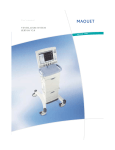
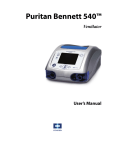
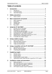
Front panels
G
A
F
E
D
B
C
A Top panel
B Controls and display
C Door label
D Patient pressure port
E Patient air port
F Exhalation valve port
G Patient pressure meter
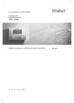
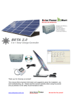
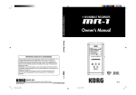
Top panel
A
B
G
F
E
C
D
A ALARM (ALERT) LIGHTS
The ventilator’s lights will flash when an alarm condition is
3-2
November 2003
Achieva Ventilator Clinician’s Manual
Description
detected. The lights are turned off when the alarm condition is
corrected and the Alarm Silence/Reset (
) switch is pressed.
See Chapter 6: Alarms and alerts for more details.
Achieva ventilators are equipped with the following alarm lights:
Low Pressure/Apnea (
High Pressure ( )
Setting Error ( )
Power Switchover (
Low Power (
)
O2 Fail
Note
)
)
( ) (Only on Achieva PSO2)
For the Achieva and Achieva PS models, which do not have the oxygen
function, the O2 alarm light position is present, but it has no light or
label.
B POWER LIGHTS
The power lights indicate which electrical source the ventilator is
currently using and if the internal battery is being charged. The
power lights include:
AC (
)
(
)
Internal Battery (
)
Battery Charging (
)
External Battery
C Alarm Control (
) Light
The Alarm Control ( ) light flashes when the audible alarm has
been presilenced. The Alarm Control ( ) light will light
continuously when the non-latching audible alarm feature is active.
See Latching and non-latching on page 6-5.
D Assist/Spontaneous (
) Light
This LED lights when the patient’s inspiratory effort is greater than
the sensitivity setting, or when the flow and pressure sensors detect
a change greater than the flow sensor or pressure trigger setting.
This is usually an indication of patient effort.
November 2003
3-3
Description
Achieva Ventilator Clinician’s Manual
E The Patient Pressure Meter shows the level of pressure which is
currently in the patient circuit. When the Test Battery (
)
switch is pressed, the patient pressure meter shows the charge level
of the battery currently in use. In some fast-cycle situations the
meter reading may not reflect the actual pressure. When precise
pressure readings are required, reference the actual values on the
display screen.
F Test Battery (
)
When the Test Battery (
) switch is pressed, the meter
shows the charge level of the battery currently in use. The test battery switch is also used to activate the ventilator’s printer output.
See Printing reports from the ventilator on page A-1.
G Alarm Silence/Reset (
)
The Alarm Silence/Reset (
) switch silences the audible
alarm during an alarm condition. The Alarm Silence/Reset
(
) switch can be used to presilence the audible alarm for a
period of 60 seconds. If an alarm condition occurs while the 60 second presilence period is in effect, or while Alarm Silence/Reset is
active, the LCD will display the alarm condition. This switch can
also be used to reset an alarm after the alarm condition has been corrected.
3-4
November 2003
Achieva Ventilator Clinician’s Manual
Description
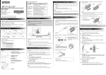
Controls and display
Ventilator
controls
Ventilation mode and
parameter controls
SIMV
Alphanumeric
display
1000
15 20 20 10 60
1.5
1:1.7
60
98
Ventilation mode and
parameter controls
The control-display panel consists of:
•
•
an alphanumeric display showing the set or current actual values of
operating parameters and ventilator information.
push-button switches that the operator uses to make selections.
The control-display panel is located behind the ventilator’s front door
panel. After beginning a ventilating mode, the display panel shows the set
values for ten seconds and then displays the actual values for each
parameter. The set value also appears for ten seconds after the value of a
setting is changed or the Start/Enter switch is pressed. Certain
parameters, such as the low pressure and high pressure alarm settings, do
not have an actual value. For these dashes (---) are displayed instead.
Following is a description of the switches’ functions. For further details see
Operating the controls on page 4-21.
Standby ( )
Use the Standby ( ) switch to place the ventilator in the standby
mode, a state where air is not being delivered.
Ventilate (
)
Use the Ventilate (
November 2003
) switch to deliver air to the patient.
3-5
Description
Achieva Ventilator Clinician’s Manual
MENU/ESC
The MENU/ESC switch activates the menu options on the ventilator’s
display.
Up and Down arrow keys
The up and down arrow keys operate in three ways:
•When a ventilation parameter is flashing, use the up/down keys
to scroll to the required setting.
•When the MENU/ESC button has been pushed, use the up/down
keys to scroll to the required menu.
•Pressing the up/down keys when neither a menu nor a parameter
is active will cause the last alarm message to be displayed.
Start/Enter (
)
When the ventilator is in Standby, pressing the Start/Enter
(
)
switch will activate the display. Start/Enter (
) switch is also
used to accept the currently flashing parameter as the new setting.
MODE
The MODE section of the display screen shows the current ventilation
mode setting. Pressing the MODE switch causes the current mode on
the display to flash and allows the ventilation mode to be changed.
Volume (Vt)
The Volume (Vt) section of the display screen shows the set or actual
volume of air that is to be delivered to the patient’s lungs during volume breaths. Pressing the Volume (Vt) switch causes the current set
value of the volume setting to flash and allows it to be changed.
Inspiratory Time (Ti)
The Inspiratory Time (Ti) section of the display screen shows the
length of time it takes the ventilator to deliver the volume and pressure control breaths to the patient. Pressing the Inspiratory Time (Ti)
switch causes the current set value of inspiratory time to flash and
allows it to be changed.
3-6
November 2003
Achieva Ventilator Clinician’s Manual
Description
Flow ( )
The Flow ( ) section of the display shows the average air flow delivered to the patient. This calculated value is given in liters/minute.
Sensitivity (SENS.)
The Sensitivity (SENS.) section of the display screen shows the amount
of flow generated by the patient that will trigger an assisted breath.
Pressing the Sensitivity (SENS.) switch causes the current set value for
sensitivity to flash and allows it to be changed.
Sensitivity (F, P, or M)
The letters F, P, or M on the alphanumeric display indicate whether
breath cycles are initiated by the patient ( F standing for Flow, P for
Pressure) or by the ventilator ( M for Machine breath).
Note
When using PEEP, use the pressure trigger along with sensitivity (Flow
Trigger). The pressure trigger setting can be accessed and changed as a
menu option. See Pressure trigger on page 5-5.
Breath Rate (f)
The Breath Rate (f) section of the display screen shows the rate at
which volume and pressure control breaths are delivered.( After entering Spontaneous mode, use the up and down arrows to select “Y” or
“N” in the alphanumeric display to activate or deactivate the automatic apnea back-up rate). Pressing the Breath Rate (f) switch causes
the current set value for breath rate to flash and allows it to be
changed.
Pressure (P)
The Pressure (P) section of the display shows the pressure level maintained during either a pressure supported breath or a pressure controlled breath. Pressing the Pressure (P) switch causes the current set
value for pressure to flash and allows it to be changed.
PEEP
The PEEP (Positive End Expiratory Pressure) section of the display
screen shows the pressure maintained at the end of a delivered breath.
Pressing the PEEP switch causes the current PEEP setting to flash and
allows it to be changed. You should consider setting the pressure trigger when using PEEP. This allows the patient to initiate either an
November 2003
3-7
Description
Achieva Ventilator Clinician’s Manual
assisted or supported breath. The pressure trigger will function relative to the PEEP setting baseline. When using PEEP, use the pressure
trigger along with sensitivity (Flow Trigger). The pressure trigger setting can be accessed and changed as a menu option. See Pressure trigger on page 5-5.
Low Pressure ( )
The Low Pressure (
) limit section of the display shows the minimal pressure limit that must be exceeded to prevent a Low Pressure
alarm. The Low Pressure alarm sounds after two consecutive cycles
below the low pressure limit. The Low Pressure alarm sounds for a valley alarm after two consecutive breath cycles that do not fall below the
low pressure limit. See Valley Pressure Alarm on page 6-6. Pressing
the Low Pressure ( ) switch causes the current low pressure limit
setting to flash and allows it to be changed. When adjusting the Pressure (P) setting, the Low Pressure ( ) will adjust automatically to
at least 1 cmH2O above the PEEP setting.
Note
Some circuit components will prevent a Low Pressure alarm by keeping
the pressure in the circuit above the alarm limit. Examples of these components include hydrated heat and moisture exchangers (HMEs) and tracheostomy tubes. If the patient circuit is disconnected from the patient, but
still connected to these components, a Low Pressure/Apnea ( ) alarm
may not sound. See Setting the low pressure alarm on page 4-26.
High Pressure ( )
The High Pressure (
)
section of the display shows the highest
pressure the ventilator will allow without sounding the High Pressure
) switch causes the current
alarm. Pressing the High Pressure (
high pressure limit setting to flash and allows it to be changed.
I/E Ratio (I/E)
The I/E Ratio (I/E) display shows the ratio of inspiratory to expiratory time. Achieva ventilators permit a range of inspiratory times from
0.2 seconds to 5.0 seconds. The I:E ratio is calculated according to the
formula:
I:E Ratio = (1/(Breath Rate) - (Inspiratory Time)) / (Inspiratory Time)
3-8
November 2003
Achieva Ventilator Clinician’s Manual
Description
FIO2 (O2%) (Only on Achieva PSO2)
The FIO2 (O2%) display shows the set enriched oxygen level. Pressing
the FIO2 (O2%) switch causes the current setting to flash and allows it
to be changed. A setting of over 21 will activate the internal O2
blender.
Note
November 2003
For the Achieva and Achieva PS models that do not have the oxygen function, the FIO2 switch is present, but it has no label and is inoperative.
3-9
Description
Achieva Ventilator Clinician’s Manual
Back and sides
J
I
H
G
F
E
D
C
A
B
A Inlet filter
Filters air as it enters the ventilator.
B Power cord connector
C External battery connector
Used for connecting an external battery.
D Side rails
Used for mounting some accessories on the ventilator.
E Audible alarm port (on side of ventilator)
DO NOT BLOCK.
F Communications connector
This connector is used to connect a printer, external modem or a
computer (with the Achieva Report Generator software) directly to
the ventilator. Follow the accessory manufacturer’s connection
instructions for the appropriate connection procedure.
G Nurse call output
The ventilator can be connected to nurse call stations through this
output. See Connecting to a nurse call system on page 4-19.
3-10
November 2003
Achieva Ventilator Clinician’s Manual
Description
H Remote alarm connector
The remote alarm cable plugs into the remote alarm cable jack on
the back of the ventilator. Be sure it is firmly in place. The cable
slips in only if you have the button on the end of the connector
facing down. To remove the cable from the ventilator, press the
button and pull the connector straight out.
I Modem connector (North America only. Outside North America
use an external modem.) For all models there is a label but no
connector.
J Oxygen input connection (only on Achieva PSO2). Connect the
optional internal O2 blender to an oxygen source with a standard
oxygen connection hose. Screw the hose fitting tightly onto the
oxygen input connection. The hose fitting must be compatible with
a 9/16-18, DISS 1240 male connector.
Note
For the Achieva and Achieva PS models there is a label but no connector.
NIST adapter kits are available.
Note
Flow is measured at the output port of the ventilator. These measurements
must be corrected for altitude (using the Altitude setting) and have an
accuracy of ±2 LPM at nominal barometric pressures. Pressure measurements are taken at the patient end of the breathing circuit. Pressure measurements are relative to the current atmospheric pressure and have an
accuracy of ±2.5 hPa.
November 2003
3-11
Description
Achieva Ventilator Clinician’s Manual
Inside door label
The following are the labels that appear on your ventilator.
This label appears on the inside of the door and provides the following
information:
• The intended use for the ventilator.
•
A warning not to use the ventilator where flammable anesthetics are
present (English and French).
•
A caution against opening the ventilator, and against attempting to
service it.
•
A warning that the ventilator, like all devices, can fail unpredictably
(English and French).
•
A statement that you must read and understand this manual before
operating the ventilator.
Top label
This label is located on the top of your ventilator. It provides abbreviated
information on responding to alarms. For more information, see Alarms on
page 6-1.
3-12
November 2003
Achieva Ventilator Clinician’s Manual
Description
or from external to internal battery.
.
A fully depleted internal battery will be fully charged in 12 hours.
45 minutes
under normal load conditions.
A fully depleted internal battery will be fully charged in 12 hours.
Side label
This label cautions you not to block the opening for the audible alarm.
Blocking the opening may prevent you from hearing the alarm.
Agency symbols label
This label, on the back of the ventilator, gives regulatory certification
information concerning your ventilator.
November 2003
3-13
Description
Achieva Ventilator Clinician’s Manual
Back panel label
The following information is printed on the back of your ventilator:
The paragraphs warn of a fire hazard if you use replacement fuses that are
not the same type and rating as the original fuses.
3-14
November 2003
Achieva Ventilator Clinician’s Manual
Description
Accessories
The instructions for the proper use of accessories will vary depending on
the manufacturer. Follow the directions given to you by the manufacturer.
The use of accessory equipment not complying with the equivalent safety
requirements of the equipment may lead to a reduced level of safety of the
resulting system. Consideration relating to the choice shall include
evidence that the safety certification of the accessory has been performed in
accordance to the appropriate IEC 601-1 and/or IEC 601-1-1 harmonized
national standard.
Caution
Use only Puritan Bennett-approved accessories with
the ventilator. The use of other accessories may
damage the unit and endanger the patient.
Accessories you may need include:
•
•
•
•
•
•
•
•
•
•
Patient circuit
Exhalation valve
Air inlet filter
Bacteria filter
Humidifier system
Printer
Modem
External battery
Remote alarm
Achieva Report Generator
Refer to the Achieva Approved Accessories Sheet that was shipped with your
ventilator for more information.
November 2003
3-15
Description
3-16
Achieva Ventilator Clinician’s Manual
November 2003
Achieva Ventilator Clinician’s Manual
Set up
Chapter 4: Set up
This chapter provides instructions for unpacking and setting up Achieva
ventilators. This chapter includes a visual inspection and user self test for the
ventilator. Instructions for setting the low pressure alarm are included.
Unpacking
To unpack your ventilator, follow the directions on the package. The
information presented here is for your convenience.
1. Remove the manuals and other material from the top of the package.
2. Pull the ventilator out of the box using the handles on the insert.
3. Remove the ventilator from the insert and from the plastic bag.
Save all packaging material. Always ship the ventilator in the supplied
packaging material. If you need replacements for your packaging, contact
Puritan Bennett.
November 2003
4-1
Set up
Achieva Ventilator Clinician’s Manual
Inspection
1. When you first get your ventilator you should perform a visual
inspection of the device. Make sure that:
•The power cord does not have any kinks, breaks or damaged
insulation.
•The connectors, rubber feet, filter housings, etc. are not loose or
broken.
•The outer casing has no dents or scratches which may indicate
dropping or other abuse.
•All the labels and markings on the ventilator are clear and
legible.
If the ventilator does not pass the visual inspection, contact your
equipment supplier or Puritan Bennett Technical Support at 1800-255-6774.
This visual inspection should be performed each time the ventilator is used after storage as well as periodically during normal use.
If the ventilator does not pass the inspection, provide an alternate
means of ventilation and contact your equipment supplier or Puritan Bennett Technical Support.
2. Wipe the ventilator with a mild soap solution, if necessary.
3. Make sure that a new air filter has been installed. See Flatpak filter
on page 8-3.
4. Plug in the ventilator to a functioning, grounded electrical outlet.
Note
During storage the internal battery may lose its electrical charge. Leave the
ventilator plugged in for a minimum of twelve hours to recharge the battery fully.
5. The ventilator will activate the audible alarm and all the visual
alarms for a period of one or two seconds. Verify that all the visual
alarm indicators light up and the audible alarm makes a tone. If
not, the ventilator is in need of repair. Do not use the ventilator
until the problem has been corrected.
6. Turn the ventilator on. See Starting the ventilator on page 5-1.
4-2
November 2003
Achieva Ventilator Clinician’s Manual
Set up
7. Follow the steps for the self test. See User self test on page 4-23.
If the ventilator does not pass the self test, contact your equipment
supplier or Puritan Bennett Technical Support.
If the ventilator passes the self test, set the ventilator’s parameters
according to the prescription. See Operating the controls on page
4-21.
Accessory checklist
Achieva ventilators need the following items to function properly:
• AC source or external battery
•
Bacteria filter
• Patient circuit
•
Air inlet filter
• Means of connection to patient
November 2003
4-3
Set up
Achieva Ventilator Clinician’s Manual
Power
Any one of three power sources can power the ventilator:
• External AC
• Internal 24 VDC battery
•
External 24 or 12 VDC battery (Use 24 VDC for optimum performance.)
When plugged into a functioning wall outlet the ventilator automatically
selects AC power. It will operate indefinitely on AC. All three sources may
be connected to the ventilator at the same time. If the AC power fails, the
ventilator automatically switches to the next best power source.
AC Power
The ventilator has a hospital grade, 3-pronged AC power connector. Note,
however, that the connector’s hospital grading depends on its use in a
hospital grade outlet. If you encounter a 2-pronged outlet, have an
electrician replace it with a properly grounded 3-pronged outlet. Where
the integrity of the external protective earth conductor arrangement is in
doubt, the ventilator shall be operated from its internal electrical power
source.
Warning
This equipment must be protectively earthed.
Mains isolation is accomplished by disconnecting the power cord from AC
power.
The plug may not fit the outlets in some countries. There are two
solutions. Replace the ventilator’s plug with one designed for the local
outlets or use an adaptor.
Caution
If you have questions about the power line, contact a
qualified electrician or Puritan Bennett.
Caution
If you have questions about how the ventilator will
operate, contact Puritan Bennett Technical Support.
4-4
November 2003
Achieva Ventilator Clinician’s Manual
Warning
Set up
If you have doubts about the ground connection,
have a qualified electrician examine the outlets. If
necessary, have them properly grounded.
When operating on AC power, the ventilator will recharge the internal
battery in any ventilation mode, including Standby. The internal battery
will charge from the external battery only when the ventilator is operating
(not in standby). AC power does not recharge the external battery when
connected to the ventilator. The external battery can be charged by a
battery charger only.
External Battery 24 Volt DC
Whenever AC power is unavailable, the ventilator can operate from an
external 24 VDC battery. Use a special cable from Puritan Bennett to
connect the ventilator to the battery. Use only Puritan Bennett-approved
batteries. A power switchover alarm signals a change from AC to external
battery or from external to internal battery.
Puritan Bennett recommends use of a 24 VDC external battery for optimal
perfomance. Although a 12 V battery can power the ventilator, a Setting
Error alarm is more likely to occur with the use of a 12 V battery under
extremely heavy load. Refer to Appendix E (Specifications) for normal and
heavy load conditions. If you are using a 12 V battery, run the ventilator at
the intended settings before connecting it to the patient to make sure the
ventilator is able to function fully at the selected settings. As the battery
discharges, a setting alarm is more likely to occur.
Carefully connect the 24 VDC battery to the ventilator. Follow the battery
manufacturer’s instructions.
Note
Use only Puritan Bennett’s cables.
) light is lit. This
Check to see if the ventilator’s External Battery (
light signals that your ventilator is properly connected and is using the
external battery.
Note
November 2003
Do not reverse the positive and negative cables when connecting a battery
to your ventilator. If you accidentally reverse the connections, a protective
fuse may open in the battery box or in the ventilator. With the resulting
open circuit, the external battery will not provide power to the ventilator.
You must first correct the connections and install a correct replacement
fuse in the system. Only then will the external battery power the ventilator.
4-5
Set up
Achieva Ventilator Clinician’s Manual
Note
Always keep a spare fuse with your battery and cable. Contact your equipment supplier or Puritan Bennett.
Note
Batteries and connecting cables are available from Puritan Bennett. These
accessories come with instructions for connection and use. The battery and
case provided by Puritan Bennett have a cable with a three pin connector.
When properly used, this cable and connector prevent reversed
connections between the battery and ventilator. Use of other cables may
damage the ventilator or make it inoperable if the cable connections are
accidentally reversed.
External Battery 12 Volt DC
The ventilator can also operate from an external 12 VDC battery.
However, a Setting Error alarm is more likely to occur with the use of a 12
VDC battery, as the ventilator may not be able to deliver gases at the
selected parameters. Use of a 24 VDC battery is recommended if at all
possible.
4-6
November 2003
Achieva Ventilator Clinician’s Manual
Set up
Battery Performance
The internal battery will charge from the external battery only when the
ventilator is operating (not in Standby); but charging from the external
battery will reduce the power remaining in the external battery.
As they age batteries lose their capacity to retain an electrical charge. For
best performance, follow the manufacturer’s instructions.
The following affect the life of the battery:
• Ambient temperature
•
Charge level
• Storage conditions
• Age of battery
•
The number of times, and the extent to which, the battery is
discharged and recharged
• Type (12 V or 24V)
To ensure maximum running time of the ventilator on any external
battery, keep the battery fully charged. Some batteries need to be
discharged and recharged monthly. Refer to the battery manufacturer’s
instructions. Recharge any external battery immediately after use. Use a
Puritan Bennett-approved battery charger. The time required to recharge a
battery varies. With a Puritan Bennett charger, a fully depleted external
battery will be fully charged in twelve hours.
Every four to six weeks run the ventilator on the external battery until the
ventilator switches to the internal battery. Immediately disconnect the
external battery, switch to AC power and recharge the external battery
until it is fully charged.
Caution
Recharge an external battery immediately after use.
You should use a Puritan Bennett-approved battery
charger to recharge external batteries.
Caution
There is a possibility of reduced performance when
the ventilator is powered by a 12 VDC battery. In this
event, you will get a Setting Error alarm (Volume
November 2003
4-7
Set up
Achieva Ventilator Clinician’s Manual
Error, Rate Error, or Inspiratory Error alarm).
Caution
When recharging the external battery, first connect
the battery to the charger, then connect the charger
to AC power.
Caution
Never connect a battery charger to an external
battery while the battery is connected to the
ventilator. This may cause permanent damage to the
ventilator.
With a 24 or 12 volt battery, the ventilator can operate for at least 19
hours with NORMAL LOAD operating parameters. See Appendix E:
Specifications for more details. There is a possibility of reduced performance
with a 12 volt battery.
Testing the Batteries
Make sure the battery to be tested is powering the ventilator before
performing the battery test; failure to do so will result in an erroneous
reading of the battery condition. To run the test, press and hold the Test
Battery (
) switch. The needle on the meter registers the battery
charge. A fully charged battery, in good condition, will register
approximately 100% on the scale.
The battery test meter is only a relative indicator of the remaining battery
charge. An older battery may register a high charge level, but discharge
more rapidly. Carefully monitor battery power sources. Always have a
back-up power source available.
The amount of power available is directly related to the battery’s age, as
well as the number and depth of cycles the battery has delivered. As a
battery ages, its ability to power the ventilator decreases. The extent to
which a battery is discharged each time it is used also affects its longevity.
A battery that is nearly or completely discharged each time it is used will
age more quickly than one that is only partially discharged. Take both the
age of the battery and its history of use into account in all applications, but
especially in portable applications where another power source may not be
readily available. The power required by the ventilator varies with the
ventilation parameters.
4-8
November 2003
Achieva Ventilator Clinician’s Manual
Set up
The ventilator will switch to the internal battery and signal an alarm when
the external battery’s voltage drops below a preset limit. The alarm
indicates the ventilator can no longer operate reliably on the external
battery.
External battery precautions
Place the battery as far away as possible from the ventilator’s Inlet Filter
(located on the rear panel).
When using a tray to hold both the battery and the ventilator, put a
partition between the battery and ventilator.
Batteries need to be discharged and recharged monthly. Refer to the
battery instructions.
Warning
Never place the battery above or on top of the
ventilator.
Caution
Always use separate batteries to power a motorized
wheelchair and the ventilator.
Internal Battery 24 Volt DC
Before use, run the ventilator on AC power for twelve hours to make sure
the internal battery is charged. The internal battery can maintain its
charge for at most three months when the system is OFF.
The internal 24 VDC battery is intended for backup use only. It requires
no special connections. The ventilator switches to the internal battery
when other power sources fail or drop below adequate levels. The Power
Switchover alarm signals whenever the ventilator switches from AC, or an
external DC battery, to its internal battery.
Warning
If your health or safety would be jeopardized by a
long-term power failure, a reliable backup power
source is mandatory. Do not regard the internal
battery as a long-term backup power source.
When powered by the internal battery, the Internal Battery (
) light is
continuously lit. As the battery nears depletion the ventilator will give the
November 2003
4-9
Set up
Achieva Ventilator Clinician’s Manual
following alarm indications (times are based on normal load conditions as
defined in Appendix E - Specifications):
•
Low Internal Battery Alarm: When approximately 45 minutes of
power remains, the audible alarm sounds a single beep every five
minutes. Switch to an external power source.
•
Extremely Low Internal Battery Alarm: When approximately 10
minutes of power remains, the low power light flashes and the alarm
sounds three pulses (repeating) which can be silenced for five minutes
at a time by pressing the Alarm Silence/Reset
Switch immediately to another power source.
•
Note
(
)
switch.
Battery Charge Depleted: When the internal battery is nearly
) light continues to flash and the
depleted, the Low Power (
alarm sounds five pulses (repeating) that cannot be reset or silenced.
You must respond immediately and provide another source of
ventilation. Switch to an external power source and reset the
ventilator. For instructions on how to recover from this condition, see
Response to Low Internal Battery Power or Extremely Low
Internal Battery Power alarms on page 6-18.
During Low Battery and Extremely Low Battery alarms, other alarms
(such as Setting Error) can occur when the ventilator is no longer able to
deliver gases at the selected parameters.
Test the charge level of the internal battery by pushing the Test Battery
(
) switch. Read the charge level on the Battery Condition scale of
the patient pressure meter. A fully charged battery, in good condition, will
register approximately 100% on the scale.
Note
The ventilator must be operating on internal battery power to obtain a
reading of the internal battery’s charge level.
Caution
To retain the electrical charge of the internal battery,
recharge it by plugging the unit into an AC power
outlet after each use. A fully depleted internal battery
will be fully charged in twelve hours. Always charge
the internal battery before disconnecting AC power
from the ventilator.
4-10
November 2003
Achieva Ventilator Clinician’s Manual
Set up
Keep the internal battery fully charged at all times. The ventilator charges
the internal battery when it is connected to an AC power source and is in
any operating mode, including Standby.
Every four to six weeks, run the ventilator on its internal battery until the
low power alarm sounds. Immediately switch to AC power and recharge
the internal battery for at least twelve hours.
Warning
November 2003
Batteries contain toxic chemicals and no attempt to
remove or replace the internal battery should be
made by anyone other than the equipment
supplier or a trained service center.
4-11
Set up
Achieva Ventilator Clinician’s Manual
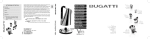
Attaching the patient circuit
The patient circuit has a long flexible hose and several other parts shown
in the diagram. It attaches to the ventilator. Inspect it every day to:
• Make sure there are no cracks in the hose.
•
Be certain all the connections are secure and free of leaks.
Clean the exhalation manifold according to the manufacturer’s
instructions.
Each time the Patient Circuit is reassembled you need to do a user self test
to make sure the circuit is functioning properly. See User self test on page
4-23.
F
A
B
C
E
D
The following instructions are for a reusable patient circuit, as illustrated.
Disposable patient circuits are also available from Puritan Bennett, and
include instructions.
A EXHALATION MANIFOLD
The exhalation manifold directs the flow of gases to and from the
patient. The exhalation manifold is also used to control PEEP and
regulate pressure during Pressure Control. This assembly consists of
a manifold body, a mushroom valve, and a cap. Refer to the
manufacturer’s instructions. Before using it with the patient, secure
all connections and ensure the seating of the mushroom valve.
4-12
November 2003
Achieva Ventilator Clinician’s Manual
Set up
During inhalation, the “mushroom” inflates and allows air to enter
the lungs. During exhalation, the “mushroom” deflates and allows
air to be expelled from the lungs. The exhalation valve is a critical
component. During pressure ventilation and PEEP the exhalation
valve is controlled to regulate pressure and PEEP.
B FLEX TUBE
This tube connects the patient circuit to the tracheostomy tube. The
tube’s flexibility makes the circuit more comfortable.
Caution
The flex tube may contain natural rubber latex
which may cause allergic reactions.
C BACTERIA FILTER
This filter cleans the incoming air before the patient inhales it.
D PATIENT AIR TUBE
This is the large tube between the bacteria filter and the exhalation
manifold.
Warning
Anti-static or conductive hoses or tubing should not
be used.
E PATIENT PRESSURE TUBE
This small tube connects the patient pressure port on the ventilator
to the proximal pressure port on the exhalation manifold.
F EXHALATION TUBE
This small tube connects the exhalation valve port to the mushroom
valve in the patient circuit.
Warning
November 2003
Ensure the proper connection and operation of the
patient circuit at least daily. The patient could be at
risk if the manifold does not function as intended.
Connecting patient pressure and exhalation tubes
to the incorrect port prevents proper patient
ventilation. Be aware that adding attachments or
other components to the breathing system will
increase inspiratory and expiratory resistances.
4-13
Set up
Achieva Ventilator Clinician’s Manual
Warning
A ventilator patient is highly susceptible to
respiratory infections. Dirty or contaminated
equipment may be a source of infection. Clean
equipment and proper use of bacteria filters are
essential to reduce the chance of infection.
Warning
For patients with respiratory failure conditions
ventilated in pressure-controlled or pressuresupported modes, the physician must determine at
what level the patient may require an alternative
means of monitoring effective ventilation.
4-14
November 2003
Achieva Ventilator Clinician’s Manual
Set up
Attaching oxygen
Connect an external oxygen source to the oxygen input connector on the
back of the ventilator (available only on Achieva PSO2). The connector is a
DISS 1240 fitting. Input pressure range is 138–552 kPa (20–80 PSIG).
NIST adapter kits are available from Puritan Bennett.
.
To start the oxygen blender, the FIO2 (O2%) setting must be above 21%.
The FIO2 (O2%) level should be set according to the prescription. The O2
Fail ( ) alarm will sound if the ventilator does not detect a flow source.
Supply pressures of less than 355 kPa (45 PSIG) may result in reduced
oxygen performance at some settings. Optimum performance is achieved
at 443 kPa (65 PSIG) oxygen supply pressure. It may take several minutes
for the oxygen concentration to stabilize. An oxygen supply capable of
delivering a minimum of 80 SLPM (Standard Liters per Minute) is
required to realize the full capacity of the blender.
The capacity of the oxygen blender is a function of tidal volume and
inspiratory time, which in combination influence peak flow. As peak flows
increase (i.e. large tidal volumes combined with short inspiratory times),
the limit of the oxygen flow capacity is approached. The set oxygen
concentration cannot be delivered if the flow capacity of the oxygen
blender has been exceeded.
Warning
November 2003
This device does not include an oxygen analyzer.
Always measure the delivered gases with a
calibrated analyzer having high and low
concentration alarms in order to ensure that the
prescribed oxygen concentrations are delivered to
the patient.
4-15
Set up
Caution
Achieva Ventilator Clinician’s Manual
Altitude changes and oxygen source pressure can
affect the ventilator’s oxygen blender. To ensure
correct oxygen blending, verify that the correct
altitude has been entered into the ventilator’s
parameters (see The Altitude Testing section in this
manual).
Two other methods of supplemental oxygen delivery are available:
•the 90° elbow with oxygen fitting
•the oxygen enrichment kit
90° Elbow with oxygen fitting Use the elbow to bleed oxygen directly into
the patient circuit. This method can achieve concentrations up to 40%.
Connect the elbow between the bacteria filter and the patient circuit.
Connect a low-pressure oxygen line to the fitting on the elbow. Use the
formula below to calculate the volume of pure oxygen to be bled into the
patient circuit to achieve the desired oxygen concentration:
BPM × V t × ( C Ð 0.21 )
LPM = ----------------------------------------------------------0.79
Where:
LPM=100% oxygen flow in liters per minute
BPM=breath rate in breaths per minute
Vt= tidal volume in liters
C= desired patient oxygen concentration (i.e., 30% = 0.3)
Note
Oxygen bled into the circuit is additional volume. Adjust for this volume
when setting the ventilator volume.
Oxygen enrichment kit You can achieve high oxygen concentrations at the
proximal airway by delivering source oxygen directly into the Air Inlet
port on the back of the ventilator. Use the optional Oxygen Enrichment
Kit. This kit contains complete instructions.
Short term humidification
When using humidification for a short time, or during transport, you can
use a heat and moisture exchanger (HME, or artificial nose) with the
ventilator. Connect this regenerative humidifier to the patient circuit
between the trach connector and the flextube, or follow the manufacturer’s
instructions.
4-16
November 2003
Achieva Ventilator Clinician’s Manual
Warning
Set up
The use of an HME or humidifier may affect the
ventilator’s low pressure alarm. See Setting the low
pressure alarm on page 4-26.
Extended Use
The patient’s doctor will usually prescribe humidification of the delivered
gases. Puritan Bennett offers special humidifier mounting brackets. The
brackets include instructions for use.
For complete instructions on the operation, cleaning, and sterilization of
the humidifier, refer to the appropriate sections of the humidifier
manufacturer’s instruction manual.
Warning
Always position the humidifier at a level lower than
the patient and at the same, or lower, level than
the ventilator. This will help prevent excessive
moisture from entering the system.
Warning
Some active humidifiers do not have temperature
monitoring or alarm capabilities. Failure to monitor
air temperature may allow inspired air to become
too hot. Thermal injury to the patient’s airway may
result. Always follow the recommendations of the
humidifier manufacturer.
Caution
Condensation forms in the patient circuit over time.
Periodically check for moisture in the patient circuit.
When present, remove the moisture. Before
November 2003
4-17
Set up
Achieva Ventilator Clinician’s Manual
attempting to dry the circuit, disconnect it from the
ventilator.
Warning
Do NOT use compressed gas to clear moisture
from the pressure line when connected to the
patient. First disconnect the ventilator and circuit.
Warning
Always drain the tubing away from the patient
connection.
Caution
Always disconnect the tubing from the ventilator
before drying with pressurized air. Failure to do so
may damage the ventilator.
4-18
November 2003
Achieva Ventilator Clinician’s Manual
Set up
Connecting to a nurse call system
The nurse call output on the back of Achieva ventilators is connected to
the contacts of a normally-open relay. During low pressure alarms, the
contacts open and close (1.67Hz, 50% duty cycle). During all other
alarms, the contacts remain closed. The contacts are also closed while the
ventilator is in Standby (non-ventilate) mode.
Pressing the Alarm Silence/Reset (
the open position.
) button resets the contacts in
Use a ¼″ phone plug (available from Puritan Bennett) to connect this
output to a nurse call station. The relay is rated at 30V, 0.5A.
If your application requires a normally-closed (open on alarm) connection,
you can change the setting by following these instructions:
1. Make sure the ventilator is unplugged and fully powered down (no
power source LED lit).
2. Use a 1/8” hex driver to remove the two screws securing the left
side rail and the left side cover (the side with the alarm). Remove
the left side rail.
3. Remove the plastic left side cover.
November 2003
4-19
Set up
Achieva Ventilator Clinician’s Manual
4. There is a label on the left side panel that looks like the sample
shown below:
Nurse Call System
NC/NO Connector
Configuration
HIGH
N.C.
Position
N.O.
Position
LOW
5. Insert a small, nonconductive screw driver through the left adjustment hole in the side panel and slide the switch to the right until
it clicks into position. (The right adjustment hole is for changing
the alarm volume level.)
6. Insert the tabs on the bottom of the plastic left side cover into the
groove at the bottom of the left side panel. Reposition the left side
cover into place.
7. Secure the left side rail and the left side cover using a 1/8” hex
driver and the two screws removed in step two.
8. Connect the nurse call system that will be used to the nurse call
jack on the back of the ventilator and test for proper operation.
The nurse call system should be alerted during an alarm condition,
or when the ventilator is set to Standby.
4-20
November 2003
Achieva Ventilator Clinician’s Manual
Set up
Operating the controls
Ventilator
controls
Alphanumeric
display
SIMV
1000
15 20 20 10 60
1.5
1:1.7
60
98
Ventilation mode and
parameter controls
Ventilator
controls
After beginning a ventilating mode, the display panel shows the set values
for ten seconds and then displays the actual values for each parameter. The
set value also appears for ten seconds after the value of a setting is changed.
Certain parameters, such as the low pressure and high pressure alarm
settings, do not have an actual value. For these dashes (---) are displayed
instead.
To set the ventilator’s parameters:
1. Press the Start/Enter (
) switch. The current settings will be
displayed.
2. Press the switch for the parameter that you wish to change. The
displayed setting will begin to flash.
3. Use the up and down arrow keys to adjust the parameter’s value.
4. When the prescribed value is displayed, press the Start/Enter
(
) switch to accept the setting.
If a setting is not displayed: Some parameter selections make it
unnecessary to select certain other parameters; for example, spontaneous
mode makes it unnecessary to select a breath rate. If a parameter is not
November 2003
4-21
Set up
Achieva Ventilator Clinician’s Manual
displayed, one of your other selections has made that parameter
unnecessary.
If a setting is flashing: If a parameter is flashing, the ventilator is waiting
for you to enter a value for that parameter. Use the up and down arrows to
select the appropriate value, then press Start/Enter (
4-22
).
November 2003
Achieva Ventilator Clinician’s Manual
Set up
User self test
While in the Standby mode, you can perform tests that assess whether or
not the ventilator’s pneumatic system is working properly. This test
requires your assistance. The user self test is accessible only when in
Standby.
1. While in Standby, press the MENU/ESC key.
2. The user self test is the first item in the menu.
Press ENTER to begin
User Self Test
3. Press the Start/Enter (
) key.
The following message will display:
Occlude patient Õ s
end of breathing circuit.
4. Block the part of the exhalation manifold that connects to the
patient. It is important that you make a tight seal and do not let
any air escape.
Warning
A ventilator patient is highly susceptible to
respiratory infections. Dirty or contaminated
equipment may be a source of infection. Clean
equipment is essential for successful ventilation. Be
sure to wash your hands thoroughly before and
after contact with the patient circuit.
The following message will display:
Press ENTER when ready
to begin test
5. When you have a good seal on the Exhalation Manifold, press the
Start/Enter (
) key.
November 2003
4-23
Set up
Achieva Ventilator Clinician’s Manual
The ventilator will push air into the circuit as it runs the test.
6. If the ventilator passes the test, the following message will display:
TEST PASSED.
ENTER: repeat ESC: exit
Press the Start/Enter (
) switch if you wish to repeat the
test, or the MENU/ESC switch to end the test and place the ventilator into Standby.
7. If the ventilator fails the test, one of three messages will be displayed.
Test ERROR.
Refer to MANUAL
If this message is displayed, it means the test was not conducted
properly.
•
Press the ALARM SILENCE/RESET switch. The display screen will
indicate that the test was a failure:
Test FAILED.
•
•
ENTER: repeat ESC: exit
Check all the connections in the patient circuit, including the
blockage in the exhalation manifold.
Press START/ENTER to repeat the test.
Leak Test FAILED.
Refer to MANUAL.
•
•
4-24
If this message is displayed, it means that there is a leak in the
patient circuit somewhere between the patient air port and the
blockage you created at the exhalation manifold.
Acknowledge the alarm condition by pressing the ALARM SILENCE/
RESET switch. The display screen will indicate that the test was
a failure.
November 2003
Achieva Ventilator Clinician’s Manual
Set up
Test FAILED.
ENTER: repeat ESC: exit
• Press START/ENTER to repeat the test.
• If the ventilator fails the test again try using a new patient
circuit and repeat the test. If the ventilator fails with a new
patient circuit, contact your equipment supplier or Puritan
Bennett.
Relief valve test FAILED.
Refer to MANUAL
If this message is displayed, it means that the ventilator’s relief valve did
not function properly
• If the ventilator fails the test again, contact your equipment
supplier or Puritan Bennett.
November 2003
4-25
Set up
Achieva Ventilator Clinician’s Manual
Setting the low pressure alarm
Warning
Throughout this procedure, the ventilator must be
disconnected from the patient. Provide another
means of ventilation.
Some patients will be in danger if they become disconnected from the
ventilator. The purpose of the low pressure alarm is to detect such a
disconnection, but the ventilator can only do so if it is adjusted properly.
Warning
Some patient circuit components can defeat a low
pressure alarm by keeping the pressure in the
circuit above the alarm limit. Examples of such
components include hydrated heat and moisture
exchangers (HMEs) and tracheostomy tubes.
For all ventilator patients who cannot respond appropriately to this
situation, the clinician must set the low pressure alarm to a level that
permits an alarm to be detected in the event of a disconnection.
Before adjusting the low pressure alarm keep these points in mind:
4-26
•
The low pressure alarm must be set for the exact configuration of
patient circuit components, including the tracheostomy tube, and the
mode of ventilation. If you add, remove or change components,
readjust the low pressure alarm.
•
When PEEP is used, the low pressure alarm setting cannot be set
lower than the PEEP setting. The settings will flash together if you
try to set the low pressure alarm below the PEEP setting.
•
The HME is a substitute for an active humidifier; do not use the two
together.
•
The HME’s resistance to air flow increases as it becomes moist with
use. After a period of time, which will depend on the patient and the
HME, the low pressure alarm must be readjusted. Consult your doctor
and the manufacturer of the HME to determine the appropriate
period.
November 2003
Achieva Ventilator Clinician’s Manual
Set up
Follow these steps to set the low pressure alarm:
1. Assemble the patient circuit exactly as it will be used by the
patient. Attach all accessories, including the HME (if used), the
tracheostomy tube or inner cannula of dual lumen tracheostomy
tubes.
2. Verify that the ventilator’s parameters are set as prescribed by the
doctor. Change them if necessary.
3. Press Ventilate (
) to begin breath delivery.
4. Adjust the Low Pressure (
) setting until a low pressure alarm
occurs. Note that it takes two breath cycles for the alarm to sound.
Warning
Repeat this procedure whenever you change,
replace, remove or reconnect components of the
patient circuit, or alter the ventilator’s parameters.
Warning
It is possible that with the low pressure alarm set
as described above, the patient’s breathing effort
will cause continuous low pressure alarms. In this
case, you may lower the low pressure setting until
alarms no longer occur during normal operation,
but an independent method of measuring
ventilation will be mandatory.
November 2003
4-27
Set up
4-28
Achieva Ventilator Clinician’s Manual
November 2003
Achieva Ventilator Clinician’s Manual
Operation
Chapter 5: Operation
This chapter provides information on starting and stopping the ventilator and
setting the various modes and menu selections. It includes a monthly safety
check, and a list of the information the patient and caregiver must know to use
the ventilator safely and effectively.
Starting the ventilator
Ventilator
controls
Alphanumeric
display
SIMV
1000
1.5
15 20 20 10 60
60
1:1.7
5
98
Ventilation mode
and parameter
controls
Ventilator
controls
In the standby mode of operation the ventilator does not deliver air to the
patient. The ventilator can be kept in the standby mode indefinitely when
it is connected to AC power. While on Standby, the ventilator charges the
internal battery, and the power indicators AC (
) and Battery
Charging (
) will light. When powered from a battery, the ventilator
will remain in standby for 30 seconds and then switch automatically to the
low power mode. Press the Start/Enter
ventilator out of the low power mode.
November 2003
(
)
switch to bring the
5-1
Operation
Achieva Ventilator Clinician’s Manual
To start the ventilator:
1. Press the Start/Enter (
) switch.
The ventilator will be in Standby and the current parameter settings will be displayed.
2. Check to make sure the parameters are set according to the physician’s prescription.
If the parameters are set incorrectly, adjust them at this time. See
Operating the controls on page 4-22.
3. Press the Ventilate (
) switch to start ventilation.
As ventilation starts, check the following:
•The ventilator’s LEDs will light and an audible alarm will sound
for one second. Then ventilation will begin. Verify that all the
LED indicators light up and the alarm sounds an audible tone. If
not, the ventilator is in need of repair. Do not use the ventilator
until the problem has been corrected.
•Read the pressure trigger and altitude settings that flash on the
display when the Ventilate ( ) switch is pressed. Verify that
these settings agree with the prescribed values.
For the patient’s safety, when the ventilator is plugged into AC or
switched up from low power mode, the ventilator releases the first breath
through the exhalation manifold. The unit’s microprocessor requires one
cycle to establish its reference point; that is, the operating mode and settings to use. This operation prevents delivery of incorrect volumes that
could result in excessive pressure build-up.
Stopping the ventilator
To stop the ventilator, disconnect the ventilator from the patient. Then
press and hold the Standby
Note
5-2
( ) switch for at least three seconds.
The ventilator can remain in standby indefinitely when connected to AC
power. While in Standby, the ventilator charges the internal battery, and
November 2003
Achieva Ventilator Clinician’s Manual
Operation
the power indicators (A.C. (
) and Battery Charging (
) will
light. When connected to battery power (internal or external), the units
will be on Standby for 30 seconds, then switch to the low power mode.
Sensitivity and adjustment
By default, Achieva ventilators use flow to trigger patient-initiated
breaths. The ventilator can also be set to trigger on both flow and pressure.
Flow triggering is always active. (Pressure triggering may result in
improved response to patient demand.) If the ventilator is set to trigger on
both flow and pressure, it will respond to the threshold that is reached
first. When using PEEP, consider setting the Pressure Trigger, along with
the sensitivity setting (Flow Trigger). See Pressure trigger on page 5-5.
Display of settings
Achieva ventilators display the set values for all parameters when not
ventilating. In a ventilating mode, the ventilator displays the set values for
ten seconds and then displays the actual values. The set value also appears
for ten seconds after the value of a setting is changed or the Start/Enter key
is pressed. The set values and the actual values are never displayed at the
same time. Certain parameters (e.g. low pressure and high pressure alarm
settings) do not have an actual value and dashes (---) are displayed instead.
Changing modes
When beginning ventilation in any particular mode, the settings in effect
the last time that mode was used are saved. Before starting ventilation
again or when switching to a different mode of ventilation, check the
values for all parameters.
November 2003
5-3
Operation
Achieva Ventilator Clinician’s Manual
Flow trigger
Use the sensitivity parameter to set the amount of flow the patient must
generate before the ventilator will deliver a patient-triggered breath. The
sensitivity parameter range is 3 to 25 LPM (liters per minute) in
increments of 1 LPM. The breath will be delivered to the patient when
flow is within ±0.5 LPM of the sensitivity setting.
To set flow sensitivity:
1. If the settings are not displayed, press Start/Enter (
). The
settings will appear on the display.
2. Press the Sensitivity (SENS.) switch. The displayed setting will
begin to flash.
3. Use the up and down arrow keys to select the flow, in liters per
minute.
4. When the prescribed value is displayed, press the Start/Enter
(
5-4
) switch to accept the setting.
November 2003
Achieva Ventilator Clinician’s Manual
Operation
Pressure trigger
The pressure trigger can be set to OFF, or 1 to 15hPa (in increments of
1hPa) below the baseline pressure. When using PEEP, set the Pressure
Trigger, along with the sensitivity setting (Flow Trigger). See Flow
trigger on page 5-4.
To set the pressure trigger level:
1. Press the MENU/ESC switch.
The display shows the first menu item.
2. Use the up and down arrows to scroll to the message:
Press ENTER to change
pressure trigger
3. Press the Start/Enter (
) switch.
The display shows the message:
Trigger Level: XXX
UP/DN: change ENTER: keep
4. Use the up and down arrow keys to select the prescribed pressure
trigger level.
5. Press Start/Enter (
November 2003
) to accept the setting.
5-5
Operation
Achieva Ventilator Clinician’s Manual
Altitude setting
Changes in barometric pressure can affect the operation of the Achieva
PSO2 ventilator’s oxygen blender. Each ventilator must be set for the
altitude of the location where it will be used. The altitude can be set from
0 meters (0 feet) to 4500 meters (14,760 feet), in increments of 100 meters
(328 feet).
To set or change the altitude setting:
1. Press the MENU/ESC switch.
The display shows the first menu item.
2. Use the up and down arrows to scroll to the message:
3.
Press ENTER to change operating altitude
Press the START/ENTER switch.
The display shows the message:
Altitude: XXXX m XXXXX ft
4.
UP/DN: change ENTER: keep
Use the up and down arrow keys to select the prescribed altitude
setting.
5. Press START/ENTER to accept the setting.
5-6
November 2003
Achieva Ventilator Clinician’s Manual
Operation
Assist/Control mode, volume breaths
To operate the ventilator in Assist/Control mode, delivering breaths of a
selected volume:
1. Press MENU/ESC to enter the ventilator’s menu system.
2. Set alarm latching (see Latching and non-latching on page 6-4),
or pressure trigger level (see Pressure trigger on page 5-5) and/or
operating altitude (see Altitude setting on page 5-6) from the
menu, as needed.
3. From standby, press Start/Enter (
) to display the parame-
ters.
4. Set MODE to A/C.
5. Set the prescribed volume.
6. Set the prescribed inspiratory time.
7. Set the inspiratory sensitivity to an appropriate level.
8. Set the breath rate.
9. Set Pressure to 0.
10. Set PEEP as required.
11. Set the low pressure and high pressure alarm levels. See Setting the
low pressure alarm on page 4-27.
12. If required, set FIO2 (available only on Achieva PSO2).
13. Press Ventilate (
November 2003
) to begin breath delivery.
5-7
Operation
Achieva Ventilator Clinician’s Manual
Limiting inspiratory flow (Flow Acceleration)
When using pressure control in modes with pressure-supported and
pressure-controlled breaths, you can set the ventilator to limit the
inspiratory flow rate. The flow acceleration can be turned on or off. When
flow acceleration is off, the ventilator delivers maximum flow with
relatively little pressure integration. When on, the flow is metered to 180
lpm maximum.
Warning
The clinician must be aware that limiting flow
below the patient’s inspiratory demand will limit
airway pressure and may prevent adequate
ventilation. Close monitoring of patient parameters
is essential to ensure that the patient is adequately
ventilated.
To set inspiratory flow limitation:
1. Press the MENU/ESC key.
2. Press the up or down arrow keys until the display shows the message:
3.
Press ENTER to change flow acceleration
Press the START/ENTER key. The display shows the current setting:
Flow acceleration: OFF
4.
UP/DN: change ENTER: keep
Use the up and down arrow keys to enable (“ON”) or disable
(“OFF”) flow acceleration.
5. Press START/ENTER to accept the setting.
5-8
November 2003
Achieva Ventilator Clinician’s Manual
Operation
Expiratory sensitivity
The expiratory sensitivity level is a percentage of peak flow at which a
pressure-supported breath will be terminated. The expiratory sensitivity
level has settings of 15% to 55% in 10% increments. To set the expiratory
sensitivity:
1. Press the MENU/ESC key.
2. Press the up or down arrow keys until the display shows the message: Press ENTER to set Expiratory Sensitivity.
3. Press the ENTER key.
4. Use the up or down arrow keys to change the expiratory sensitivity
level in 10% increments.
5. Press ENTER to accept the setting.
November 2003
5-9
Operation
Achieva Ventilator Clinician’s Manual
Assist/Control mode, pressure-controlled
Warning
For patients with respiratory failure conditions
ventilated in the pressure-controlled or pressuresupported modes, the physician must determine at
what level the patient may require an alternate
means of monitoring effective ventilation.
To operate the ventilator in Assist/Control mode, pressure controlled:
1. Press MENU/ESC to enter the ventilator’s menu system.
2. Set alarm latching (see Latching and non-latching on page 6-5),
or pressure trigger level (see Pressure trigger on page 5-5) and/or
operating altitude (see Altitude setting on page 5-6) from the
menu, as needed.
3. From standby, press Start/Enter (
) to display the parame-
ters.
4. Set MODE to A/C.
5. Set pressure support to the level prescribed (greater than 0). Volume will not be displayed.
6. Set inspiratory sensitivity to an appropriate level.
7. Set the breath rate.
8. Set inspiratory time for the period the ventilator must maintain
the pressure.
9. Set PEEP as required.
10. Set the low pressure and high pressure alarm levels. See Setting the
low pressure alarm on page 4-27.
11. If required, set FIO2 (available only on Achieva PSO2).
12. Set Flow Acceleration to ON or OFF.
13. Press Ventilate (
5-10
) to begin air delivery.
November 2003
Achieva Ventilator Clinician’s Manual
Operation
SIMV mode with pressure support
Warning
For patients with respiratory failure conditions
ventilated in the pressure-controlled or pressuresupported modes, the physician must determine at
what level the patient may require an alternate
means of monitoring effective ventilation.
To operate the ventilator in SIMV mode with pressure support (Achieva
PS and PSO2 only):
1. Press MENU/ESC to enter the ventilator’s menu system.
2. Set alarm latching (see Latching and non-latching on page 6-5),
pressure trigger level (see Pressure trigger on page 5-5) and/or
operating altitude (see Altitude setting on page 5-6) from the
menu, as needed.
3. From standby, press Start/Enter (
) to display the parame-
ters.
4. Set MODE to SIMV.
5. Set the prescribed volume.
6. Set the prescribed inspiratory time.
7. Set the inspiratory sensitivity to an appropriate level.
8. Set the breath rate for the prescribed number of volume breaths
per minute. All other breaths delivered will be pressure-supported
breaths.
9. Set both pressure support and PEEP to the prescribed level of pressure support.
10. Set the low pressure and high pressure alarm levels. See Setting the
low pressure alarm on page 4-27.
11. If required, set FIO2 (available only on Achieva PSO2).
12. Set the Expiratory Sensitivity
13. Press Ventilate (
November 2003
) to begin breath delivery.
5-11
Operation
Achieva Ventilator Clinician’s Manual
SIMV mode with CPAP
To operate the ventilator in SIMV mode with CPAP:
1. Press MENU/ESC to enter the ventilator’s menu system.
2. Set alarm latching (see Latching and non-latching on page 6-5),
or pressure trigger level (see Pressure trigger on page 5-5) and/or
operating altitude (see Altitude setting on page 5-6) from the
menu, as needed.
3. From standby, press Start/Enter (
) to display the parame-
ters.
4. Set MODE to SIMV.
5. Set the prescribed volume.
6. Set the prescribed inspiratory time.
7. Set inspiratory sensitivity to an appropriate level.
8. Set the breath rate to the prescribed number of volume breaths per
minute. All other breaths delivered will be CPAP supported
breaths.
9. Set pressure support to 0.
10. Set PEEP to the prescribed level of CPAP.
11. Set the low pressure and high pressure alarm levels. See Setting the
low pressure alarm on page 4-27.
12. If required, set FIO2 (available only on Achieva PSO2).
13. Press Ventilate (
5-12
) to begin breath delivery.
November 2003
Achieva Ventilator Clinician’s Manual
Operation
Spontaneous mode with pressure support (Flow
acceleration)
When using pressure control in the Spontaneous mode, you can set the
ventilator to limit the inspiratory flow rate. The flow acceleration can be
turned on or off. When flow acceleration is off, the ventilator delivers
maximum flow with relatively little pressure integration. When on, the
maximum flow is metered to 180 lpm. For more information on Flow
acceleration, see Limiting inspiratory flow (Flow Acceleration) on page
5-8.
To operate the ventilator in spontaneous mode with pressure support
(Achieva PS and Achieva PSO2):
1. Press MENU/ESC to enter the ventilator’s menu system.
2. Press the up or down arrow keys until the display shows the message:
Press ENTER to change flow acceleration
3. Press the START/ENTER key. The display shows the current setting:
Flow acceleration: OFF
UP/DN: change ENTER: keep
4. Use the up and down arrow keys to enable (“ON”) or disable
(“OFF”) flow acceleration.
5. Press START/ENTER to accept the setting.
6. Set alarm latching (see Latching and non-latching on page 6-5),
or pressure trigger level (see Pressure trigger on page 5-5) and/or
operating altitude (see Altitude setting on page 5-6) from the
menu, as needed. Select whether or not back up breaths should be
delivered. For more details, see page 5-16.
7. From standby, press Start/Enter (
) to display the parame-
ters.
8. Set MODE to SPON.
9. Set the inspiratory sensitivity to an appropriate level.
10. Set pressure support to the prescribed level (greater than 0).
November 2003
5-13
Operation
Achieva Ventilator Clinician’s Manual
11. Set PEEP as required.
12. Set the low pressure and high pressure alarm levels. See Setting the
low pressure alarm on page 4-27.
13. If required, set FIO2 (available only on Achieva PSO2).
14. Set the Expiratory Sensitivity.
15. Press Ventilate (
5-14
) to begin breath delivery.
November 2003
Achieva Ventilator Clinician’s Manual
Operation
Spontaneous mode with CPAP (Achieva PS and
Achieva PSO2)
To operate the ventilator in Spontaneous mode with CPAP (Achieva PS
and Achieva PSO2):
1. Press MENU/ESC to enter the ventilator’s menu system.
2. Set alarm latching (see Latching and non-latching on page 6-5),
or pressure trigger level (see Pressure trigger on page 5-5) and/or
operating altitude (see Altitude setting on page 5-6) from the
menu, as needed. Select whether or not back up breaths should be
delivered. For more details, see page 5-16.
3. From standby, press Start/Enter (
) to display the parame-
ters.
4. Set MODE to SPON.
5. Set inspiratory sensitivity to an appropriate level.
6. Set pressure support to 0.
7. Set PEEP to the level of CPAP required.
8. Set the low pressure and high pressure alarm levels. See Setting the
low pressure alarm on page 4-27.
9. If required, set FIO2 (available only on Achieva PSO2).
10. Press Ventilate (
November 2003
) to begin breath delivery.
5-15
Operation
Achieva Ventilator Clinician’s Manual
Ventilation modes and apnea
In Assist/Control mode with breath rate settings of less than 6 BPM, the
ventilator will sound an apnea alarm if no patient effort occurs for 10 ±1
seconds. During an apnea alarm, the ventilator delivers controlled breaths
at a rate of 10 BPM. If the patient initiates a spontaneous breath, the
ventilator will stop the controlled breaths and return to the previous
operating parameters.
In SIMV mode with breath rate settings of less than 6 BPM, the ventilator
will sound an apnea alarm if no patient effort occurs for 20 ±1 seconds.
During an apnea alarm, the ventilator delivers controlled breaths at a rate
of 10 BPM. If the patient initiates a spontaneous breath, the ventilator
will stop the controlled breaths and return to the previous operating
parameters.
In Spontaneous mode (Achieva PS and Achieva PSO2 only), the user may
choose to activate an optional apnea back-up rate, so that the ventilator
will automatically begin to deliver breaths at 10 BPM if no patient effort
occurs for 20 ±1 seconds. Upon choosing Spontaneous mode the
alphanumeric display will show the option to enter backup rate. Use the
up and down arrows to select “Y” or “N”. The pressure setting during the
spontaneous back-up mode is equal to the Pressure Support setting before
the apnea condition began, and the I:E ratio is 1:2. If the patient initiates a
spontaneous breath while the back-up rate option is in effect, the
ventilator will return to the previous operating parameters.
If the back-up rate option is not chosen, the ventilator will sound an apnea
alarm if no breath is triggered by the patient in 20 seconds.
5-16
November 2003
Achieva Ventilator Clinician’s Manual
Operation
Monthly safety check
Perform this check at least monthly while the ventilator is in use.
Warning
Throughout this check, the ventilator must be
disconnected from the patient. Provide another
means of ventilation.
1. Perform a visual inspection of the device. Make sure that:
•The power cord does not have any kinks, breaks or damaged
insulation.
•The connectors, rubber feet, filter housings, etc. are not loose or
broken.
•The outer casing has no dents or scratches which may indicate
dropping or other abuse.
•All the labels and markings on the ventilator are clear and
legible.
This visual inspection should be performed each time the ventilator is used after storage as well as periodically during normal use.
If the ventilator does not pass the inspection, provide an alternate
means of ventilation and contact your equipment supplier or Puritan Bennett Technical Support.
2. Perform a user self test. See User self test on page 4-24.
3. Test the audible alarm and the indicator lights. Press and hold the
Alarm Silence/Reset (
) switch (while an alarm condition
does not exist) for at least five seconds. The audible alarm must
sound and all the ventilator’s indicator lights must light.
4. Connect a patient circuit to the ventilator. Connect the ventilator
to AC power.
November 2003
5-17
Operation
Achieva Ventilator Clinician’s Manual
5. Set the ventilator mode to Assist/Control (A/C). Press Ventilate
( ).
6. Block the end of the patient circuit. It is important that you make
a tight seal and do not let any air escape.
Warning
A ventilator patient is highly susceptible to
respiratory infections. Dirty or infected equipment
may be a source of infection. Clean equipment is
essential for successful ventilation. Be sure to wash
your hands thoroughly before and after contact
with the patient circuit.
At the next attempt to deliver a breath, a high pressure alarm must
occur.
7. Unblock the end of the patient circuit. Press Alarm Silence/Reset
(
) to reset the high pressure alarm.
A Low pressure/Apnea alarm must occur after two or three breath
cycles.
8. Press and hold (for at least three seconds) the Standby ( ) switch
to put the ventilator in Standby mode. Press the Alarm Silence/
Reset (
) switch to reset the Low Pressure/Apnea alarm.
Verifying Alarm Functions
Before using the ventilator, complete the following procedures to test the
function of the various alarms on Achieva ventilators. Unless stated
otherwise, the initial ventilator settings for these tests are:
Breath rate:12 BPM
High Pressure: 80 hPa
Low Pressure: 3 hPa
Volume: 500 ml
Inspiratory Time: 1.0 seconds
FIO2: 21 percent
Ventilation Mode: Assist/Control
5-18
November 2003
Achieva Ventilator Clinician’s Manual
Operation
Low Pressure
1. With the ventilator in Assist/Control mode, adjust the Volume
setting to 500ml, Inspiratory Time to 0.4 seconds, and the Low
Pressure alarm to 5 hPa.
2. Attach an approved breathing circuit to the output port of the
ventilator.
3. With the patient-end of the breathing circuit open to the atmosphere, allow the ventilator to deliver three consecutive breaths.
At the beginning of inspiration of the third breath check that:
•the LED for the Low Pressure alarm lights up,
•the LCD display indicates that a Low Pressure alarm has
occurred,
4.
•the audible alarm sounds.
Place the ventilator back in Standby mode by pressing and holding
the Standby button for three seconds. Reset the alarm.
Apnea
1. With the ventilator in Standby mode, adjust the Volume setting to
500ml, Inspiratory Time to 0.5 seconds, and the Breath Rate to 5
BPM.
2. Place the ventilator in Assist/Control mode by pressing and holding the ventilate button for one second while the parameter settings are shown on the LCD display. The ventilator will deliver a
mandatory breath upon entering Assist/Control mode.
3. Before the next mandatory breath is delivered check that:
•the LED for the Low Pressure alarm lights up,
•the LCD display indicates that an Apnea alarm has occurred,
•the audible alarm sounds.
4. Place the ventilator back in Standby mode by pressing and holding
the Standby button for three seconds. Reset the alarm.
November 2003
5-19
Operation
Achieva Ventilator Clinician’s Manual
Power Failure
1. Plug in the ventilator to an AC source and allow it to run in
Assist/Control mode.
2. Unplug the ventilator. Check that:
•the Power Switchover LED lights up,
•the message on the LCD display states that the AC source is no
longer powering the ventilator,
•the LED power-source indicators also indicate that the AC is no
longer powering the ventilator,
•the audible alarm sounds.
5-20
November 2003
Achieva Ventilator Clinician’s Manual
Operation
Continuing Pressure (Valley)
1. With the ventilator in Standby mode, adjust the Volume setting to
200ml and Inspiratory Time to 0.5 seconds.
2. Attach an approved breathing circuit to the output port of the
ventilator.
3. Connect the patient-end of the breathing circuit to a 1 liter elastic
bag (make sure that the pressure tube of the breathing circuit is
connected to the appropriate fitting on both the ventilator and the
proximal pressure port).
4. Place the ventilator in Assist/Control mode by pressing and holding the ventilate button for 1 second while the parameter settings
are showing on the LCD display. Occlude the exhalation port of
the breathing circuit’s exhalation valve.
5. Allow the ventilator to deliver four consecutive breaths. At the
beginning of the fourth breath check that:
•the LED for the Low Pressure alarm lights up,
•the LCD display indicates that a Valley alarm has occurred,
6.
•the audible alarm sounds.
Remove the occlusion and set the ventilator to Standby mode by
pressing and holding the Standby button for 3 seconds. Reset the
alarm.
Inspiratory Time (Low Volume)
1. With the ventilator in Standby mode, adjust the Volume setting to
500ml, Inspiratory Time to 0.4 seconds, and Low Pressure alarm
to 50 hPa.
2. Attach an approved breathing circuit to the output port of the
ventilator (make sure that the pressure tube of the breathing circuit is connected to the appropriate fitting on both the ventilator
and the proximal pressure port).
3. Place the ventilator in Assist/Control mode by pressing and holding the ventilate button for 1 second while the parameter settings
are showing on the LCD display.
November 2003
5-21
Operation
Achieva Ventilator Clinician’s Manual
4. Keep the patient-end of the breathing circuit open to the atmosphere and allow the ventilator to deliver one breath. During the
inspiratory phase of the breath occlude the patient end of the
breathing circuit and check that:
•the LED for the Setting alarm lights up (a High Pressure alarm
will accompany the Setting alarm),
•the LCD display indicates that an Inspiratory Time alarm has
occurred,
5.
•the audible alarm sounds.
Remove the occlusion and set the ventilator to Standby mode by
pressing and holding the Standby button for 3 seconds. Reset the
alarm.
This concludes the Monthly Safety Check.
Warning
If the ventilator fails the monthly safety check or
you cannot complete this check, refer to the
Troubleshooting Chapter of this manual, or call
your equipment supplier or Puritan Bennett.
Menu selections
The following items are set from the menu. To access the menu, press the
MENU/ESC switch.
User self test
This selection is only available if you press the MENU/ESC switch while the
ventilator is on Standby. The user self test includes a circuit leak test and a
pressure relief valve test. For more information User self test on page
4-23.
Ventilating hours
The ventilator hours menu selection allows you to see the number of
operating hours on the ventilator since the last preventive maintenance. To
5-22
November 2003
Achieva Ventilator Clinician’s Manual
Operation
keep the ventilator operating within specifications, preventive
maintenance must be performed every 6000 operating hours, or
recertification every twelve (12) months (whichever occurs first).
To display the ventilator operating hours:
1. Press the MENU/ESC key.
2. Press the up or down arrow key until the display screen says:
Ventilating hours since
last maintenance: XXXXX
Pressure trigger
The pressure trigger menu selection allows the clinician to enable or
disable pressure triggering of breath delivery, in addition to flow
triggering. When using PEEP, consider using Pressure Trigger, along
with the sensitivity setting (Flow Trigger). See Pressure trigger on page
5-5.
Date and time
The date and time menu selection allows you to set the date and time in
the ventilator’s internal memory. This information will appear in the
printed reports and the data transferred to the Report Generator software.
For information on the printed reports, see Printing reports from the
ventilator on page 1. For information on the Report Generator software,
see the Achieva Report Generator User’s Guide.
To set the date and time:
1. Press the MENU/ESC key.
2. Press the up or down arrow key until the display screen says:
Press ENTER to modify
3. Press Start/Enter (
Date and Time
).
The display screen will show the date and time.
November 2003
5-23
Operation
Achieva Ventilator Clinician’s Manual
05/18/96 01:23:30
UP/DN: change ENTER: keep
4. The first variable in the date and time will flash. This indicates
that this value can be changed. Press the up or down arrow key to
change the value.
5. When the correct setting is displayed on the screen press Start/
Enter (
) to accept the setting and move to the next date or
time variable.
6. When all six variables have been accepted, press Start/Enter
(
), then press
MENU/ESC.
5-24
November 2003
Achieva Ventilator Clinician’s Manual
Operation
What the patient and caregiver must know
The following checklist presents a summary of the topics that patients and
caregivers must understand in order to use ventilators successfully. Some
topics do not apply to some patients; some patients may require additional
information. It is the responsibility of the clinician or clinical educator to
ensure that the patient and caregiver understand the appropriate topics
fully.
For a detailed list of learning objectives for patients and caregivers, see
Learning Objectives for Positive Pressure Ventilation in the Home (National
Center for Home Mechanical Ventilation, Denver CO, July 1993). This
publication is available from Puritan Bennett.
The patient and caregiver must understand…
November 2003
❑
❑
❑
❑
❑
❑
❑
❑
❑
❑
❑
❑
❑
❑
❑
❑
The need for ventilation.
❑
❑
❑
❑
❑
❑
❑
❑
The parts and purpose of the tracheostomy and the tracheostomy tube.
The schedule for ventilation.
The supplies required for ventilation, and the sources of each.
Whom to contact for medical emergencies, equipment emergencies, or power emergencies.
How to contact other resources for assistance (health aides, attendants, therapists, etc.)
The principles of operation for the ventilator.
Power sources for the ventilator, and how to connect each.
The settings for the ventilator parameters, and the importance of each.
How to perform a user self test of the ventilator, and how to respond if the self test fails.
The preventive maintenance schedule for the ventilator.
The ventilator alarm settings, with the purpose and function of each.
How to respond to ventilator alarms.
What to do if the ventilator alarms inappropriately.
The parts and purpose of the patient circuit.
How and how often to clean and replace the patient circuit.
How to recognize and respond to problems with the patient circuit.
Care of the tracheostomy and tracheostomy tube.
How to recognize and respond to problems with the tracheostomy and tracheostomy tube.
The parts and purpose of the nasal mask.
Care of the nasal mask.
How to recognize and respond to problems with the nasal mask.
The parts and purpose of the mouth piece.
Care of the mouth piece.
5-25
Operation
Achieva Ventilator Clinician’s Manual
The patient and caregiver must understand…
❑
❑
❑
❑
❑
❑
❑
❑
❑
❑
❑
❑
❑
5-26
How to recognize and respond to problems with the mouth piece.
The purpose of the humidifier or HME.
How to connect the humidifier or HME to the ventilator and the patient circuit.
How to clean and change the humidifier or HME.
How to recognize and respond to problems with the humidifier or HME.
The oxygen setting, and why it is required.
How to connect the oxygen source to the ventilator.
How to determine the amount of oxygen available, and how to acquire more.
Safety rules for the use of oxygen.
Why a back up ventilation system is necessary, and how to use it.
How the back up ventilation system differs from the main system.
How to recognize and respond to problems with the back up ventilation system.
How to use additional equipment, such as external monitors and alarms.
November 2003
Achieva Ventilator Clinician’s Manual
Operation
The patient and caregiver must understand…
November 2003
❑
❑
❑
❑
❑
❑
❑
❑
❑
❑
How and why to monitor the patient’s condition.
❑
❑
❑
❑
❑
❑
❑
❑
❑
❑
❑
❑
Equipment and phone numbers to have available in cases of emergency.
How to check the patient’s vital signs.
The significance of the patient’s ease of breathing.
What to note about the patient’s skin, mucous membranes, and secretions, with their significance.
How to recognize the signs of infection, and how to respond.
The importance of routine medical appointments and medical testing.
The need and processes used to clear airway secretions.
The use of manually assisted coughing.
When, why, and how to use tracheal suctioning.
How to recognize and respond to problems with suctioning.
When and how to use a manual resuscitator.
How to respond to dyspnea.
How to recognize and respond to problems with the ventilator.
How to recognize and respond to problems with the oxygen supply.
How to perform cardiopulmonary resuscitation.
Techniques to prevent aspiration of vomit.
Why and how to use a delee catheter.
The importance of coordinating care for the patient.
Resources for respite care.
Choices about future care.
The purpose of advanced directives.
5-27
Operation
5-28
Achieva Ventilator Clinician’s Manual
November 2003
Achieva Ventilator Clinician’s Manual
Alarms and alerts
Chapter 6: Alarms and alerts
This chapter provides instructions on responding to ventilator alarms. A list of
all ventilator alarms and alerts is included.
To manually initiate a test of the alarms, press and hold the Alarm
Silence/Reset (
) switch (when an alarm condition does not exist)
for at least five seconds. The ventilator will activate the audible and visual
alarms for a period of one or two seconds. Verify that all the visual alarm
indicators light up and the audible alarm makes an audible tone. If not,
the ventilator is in need of repair. Do not use the ventilator until the
problem has been corrected.
Alerts indicate conditions caused by interactions between the ventilator
and the patient that are not serious enough to constitute a direct risk, but
which the operator should be aware of. They are signaled by a visual
indicator and no audible alarm.
The alarm volume can be set louder or softer to one of two levels. Contact
Puritan Bennett’s Technical Support at (800) 255-6774 for instructions on
making the necessary changes.
Warning
All alarms indicate a potential risk to patient safety.
When an alarm sounds, provide immediate
attention, care, and support to the patient as
dictated by the situation.
Pressing Alarm Silence/Reset prevents any audible
alarm from sounding for 60 seconds even if new
alarms occur during that time. If an alarm
condition occurs while the 60 second presilence
period is in effect, or while Alarm Silence/Reset is
active, the LCD will display the alarm condition.
November 2003
6-1
Alarms and alerts
Warning
6-2
Achieva Ventilator Clinician’s Manual
Any device is subject to unpredictable failures. To
ensure patient safety, an appropriately trained
caregiver should monitor ventilation. If the
patient’s condition warrants the use of an
independent secondary alarm or another external
monitoring device, the physician should prescribe
it. The physician should also determine to what
level the patient may require an alternate means of
ventilation in the event of ventilator failure.
November 2003
Achieva Ventilator Clinician’s Manual
Alarms and alerts
Alarm sounds
Following is a list of the alarm sounds and alerts generated by Achieva
ventilators:
Repeating burst of five pulses
• Low pressure/apnea
• Battery charge depleted
• Vent Inop
Repeating burst of three pulses
• Extremely low internal battery
• High pressure
• Setting error
• O2 fail
Single reminder beep
• Low internal battery (beep is repeated every five minutes)
• Minor fault condition (beep is repeated every 30 minutes)
• Serious fault condition (beep is repeated every 15 minutes) detected
during a ventilating mode
Single three-second tone
• Serious fault condition detected while ventilator is not in a ventilating
mode
Steady audible alarm
• Microprocessor failure
Repeated single beep
• Power switchover
Visual indicator with no audible alarm: alert status
• Volume setting error
• Inspiratory setting error
Alert messages are only visible if no alarms are present.
Warning
November 2003
If alarms continue to sound, provide another
means of ventilation.
6-3
Alarms and alerts
Achieva Ventilator Clinician’s Manual
Latching and non-latching
Some of the ventilator’s alarms (those that cause the low pressure LED to
flash) have the option of operating in either a latching or non-latching
mode:
• In the non-latching mode, the audible alarm will be silenced as soon as
the condition that caused the alarm is corrected. (Some alarm
conditions correct themselves.)
• In the latching mode, the audible alarm will not be silenced until the
Alarm Silence/Reset (
) switch is pressed.
To set the latching status of the alarms:
1. Press the MENU/ESC key.
2. Press the up or down arrow key until the screen displays:
Press ENTER to change
3.
Alarm Latching Status
Press the Start/Enter (
) switch. The display indicates the
alarm’s latching status and gives directions to change the status.
4. If you change the latching status of the alarms the ventilator will
indicate the new status and ask for the change to be saved.
Alarms NONLATCHING.
Press Start/Enter (
exit without saving.
Note
6-4
ENTER: save ESC: exit
) to save the new setting or MENU/ESC to
If you exit without saving, the alarm latching status will not change.
November 2003
Achieva Ventilator Clinician’s Manual
Alarms and alerts
Presilence
Alarm conditions frequently occur during setup of the ventilator. Because
the audible part of such alarms can be annoying, they can be presilenced.
Pressing the Alarm Silence/Reset (
) switch, when an alarm
condition does not exist and no alarm LEDs are lit, will prevent the
audible alarm from sounding for one minute. The alarm control LED will
flash to indicate that the audible alarm has been presilenced. Pressing the
Alarm Silence/Reset (
) switch during the presilence condition
will cancel the presilence condition. If an alarm condition has been
corrected while the audible alarm was presilenced, the alarms will be reset
and the lights will be deactivated.
Resetting alarms
Pressing the Alarm Silence/Reset (
) switch, after an alarm
condition has been corrected, will reset the alarms and deactivate the
lights.
November 2003
6-5
Alarms and alerts
Achieva Ventilator Clinician’s Manual
Alarm conditions
Low Pressure/Apnea Alarms
Low Pressure Alarm
Visual Indicator
Audible Alarm Tone
Display screen
Cause
Latching Status
Low Pressure/Apnea
(
) light will flash.
Five pulses
WARNING: Low Pressure. Attend to patient.
A low pressure alarm condition exists if the proximal pressure does not rise above the low pressure setting during the last two consecutive breath cycles. The exception is in SIMV mode when
the Low Pressure alarm setting is higher than the Pressure setting. Then the Low Pressure alarm
will occur if the peak proximal pressure of the last two consecutive volume breaths never rises
above the Low Pressure setting.
Latching/Non-Latching
Valley Pressure Alarm
Visual Indicator
Audible Alarm Tone
Display screen
Cause
Latching Status
Low Pressure/Apnea
(
) light will flash.
Five pulses
WARNING: Valley Pressure Alarm. Attend to patient.
A valley pressure alarm condition exists if the proximal pressure does not drop below the low
pressure setting during the last two consecutive machine breaths.
Latching/Non-Latching
Exhale Fail Alarm
Visual Indicator
Audible Alarm Tone
Display screen
Cause
Latching Status
6-6
Low Pressure/Apnea
(
) light will flash.
Five pulses
WARNING: Exhale Fail Alarm. Check exhalation valve.
An Exhale fail alarm condition exists when, at the start of the inspiratory cycle, the pressure in the
patient’s circuit is greater than or equal to the high pressure alarm setting.
Latching/Non-Latching
November 2003
Achieva Ventilator Clinician’s Manual
Alarms and alerts
Apnea Alarm
Visual Indicator
Audible Alarm Tone
Display screen
Cause
Latching Status
Low Pressure/Apnea
(
) light will flash.
Five pulses
WARNING: Apnea Alarm. Check sens setting.
An apnea alarm condition exists when there is no patient breathing effort or machine cycle for 10
seconds while in Assist/Control Mode or 20 seconds in SIMV or Spontaneous modes.
Latching/Non-Latching
User Self Test Error
Visual Indicator
Audible Alarm Tone
Display screen
Cause
Latching Status
November 2003
Low Pressure/Apnea
(
) light will flash.
Five pulses
Test ERROR. Refer to USER’S MANUAL.
A user self test error condition exists if during the User Self Test the pressure in the patient circuit
does not reach a sufficient level to perform the test.
Latching/Non-Latching
6-7
Alarms and alerts
Achieva Ventilator Clinician’s Manual
Leak Test Failure Alarm
Visual Indicator
Audible Alarm Tone
Display screen
Cause
Latching Status
Low Pressure/Apnea
(
) light will flash.
Five pulses
Leak test FAILED. Refer to USER’S MANUAL.
A leak test failure alarm condition exists when the patient circuit does not maintain the appropriate pressure or the exhalation valve fails to open and reduce the pressure in the patient circuit.
Latching/Non-Latching
Response to Low Pressure Alarms
1. Attend to the patient first.
2. Check the patient circuit for kinks or loose connections.
3. Fix or replace the patient circuit.
If the alarm is not corrected
1. Attend to patient first.
2. Check to see if the ventilator’s settings are correct.
3. Correct any setting errors.
4. If the ventilator’s settings are set according to a doctor’s prescription, contact your doctor or equipment supplier.
6-8
November 2003
Achieva Ventilator Clinician’s Manual
Alarms and alerts
High Pressure Alarms
High Pressure Alarm
Visual Indicator
Audible Alarm Tone
Display screen
Cause
Latching Status
High Pressure
(
) light will flash.
Three pulses
WARNING: High Pressure Alarm. Attend to patient.
The pressure in the patient circuit exceeds the high pressure limit setting.
Non-Latching
Relief Valve Test Failure
Visual Indicator
Audible Alarm Tone
Display screen
Cause
Latching Status
High Pressure
(
) light will flash.
Three pulses
Relief valve test FAILED. Refer to USER’S MANUAL.
The relief valve failed to open while the pressure was above the relief valve threshold pressure.
Non-Latching
Response to a High Pressure Alarm
1. Attend to patient first.
2. Check the patient circuit for kinks.
3. Fix or replace the patient circuit.
If the alarm is not corrected
1. Attend to patient first.
2. Check to see if the ventilator’s settings are correct.
3. Correct any setting errors.
4. If the ventilator’s settings are set according to a doctor’s prescription, contact your doctor or equipment supplier.
November 2003
6-9
Alarms and alerts
Achieva Ventilator Clinician’s Manual
Setting Error Alarms
Invalid I:E Ratio Alarm
Visual Indicator
Audible Alarm Tone
Display screen
Cause
Latching Status
The Setting Error
( ) light will flash.
Three pulses
WARNING: Invalid I:E ratio. Check settings.
A combination of setting(breath rate and inspiratory time) resulting in an inspiratory time that
exceeds the expiratory time.
Non-Latching
High Pres < Low Pres Alarm
Visual Indicator
Audible Alarm Tone
Display screen
Cause
Latching Status
The Setting Error
( ) light will flash.
Three pulses
SETTING ERROR: High Pressure < Low Pressure setting.
The low pressure limit setting is the same or higher than the high pressure setting.
Non-Latching
Volume Error Alarm
Visual Indicator
Audible Alarm Tone
Display screen
Cause
Latching Status
The Setting Error
( ) light will flash.
Three pulses
WARNING: Volume error. Attend to patient.
During a volume breath the ventilator did not deliver the set volume (±12%).
Non-Latching
Volume Error Alert
Visual Indicator
Audible Alarm Tone
Display screen
Cause
The Setting Error
( ) light will flash.
No audible alarm tone
WARNING: Volume error. Attend to patient.
With a pressure support breath the last two breaths did not stop within three seconds, or
For a pressure control breath or a pressure support breath the piston reached the end of travel on
the last two breaths.
Latching Status
Non-Latching
Pressure Differential Alarm
Visual Indicator
6-10
The Setting Error
( ) light will flash.
November 2003
Achieva Ventilator Clinician’s Manual
Audible Alarm Tone
Display screen
Cause
Latching Status
November 2003
Alarms and alerts
Three pulses.
Pressure Differential Error. Refer to manual.
The pressure levels detected by two independent sensors differ by more than 15 cmH2O
Non-Latching
6-11
Alarms and alerts
Achieva Ventilator Clinician’s Manual
Rate Error Alarm
Visual Indicator
Audible Alarm Tone
Display screen
Cause
The Setting Error
( ) light will flash.
Three pulses
WARNING: Breath rate error. Attend to patient.
In Assist/Control Mode, breaths are delivered slower than the set breath rate, or
If the breath is a volume breath (SIMV mode), the breath rate is slower than the Breath Rate setting, or
If the breath is an assisted breath (SIMV mode), the breath rate is slower than two times the
Breath Rate setting.
Latching Status
Non-Latching
Inspiratory Error Alarm
Visual Indicator
Audible Alarm Tone
Display screen
Cause
Latching Status
The Setting Error
( ) light will flash.
Repeated single beep
WARNING: Inspiratory time error. Attend to patient.
During volume breath delivery the last measured inspiratory time differed by 12% from the
inspiratory setting.
Non-Latching
Inspiratory Error Alert
Visual Indicator
Audible Alarm Tone
Display screen
Cause
Latching Status
The Setting Error
( ) light will flash.
No audible alarm tone
WARNING: Inspiratory time error. Attend to patient.
During pressure-controlled breath delivery the measured inspiratory time differed by 12% from
the inspiratory setting for the last two consecutive breaths.
Non-Latching
Response to a Setting Error Alarm
1. Attend to patient first.
2. Check the ventilator settings.
3. Correct any setting errors.
4. If the ventilator’s settings are set according to a doctor’s prescription, contact your doctor or equipment supplier.
6-12
November 2003
Achieva Ventilator Clinician’s Manual
Alarms and alerts
Equipment Alarm
Visual Indicator
Audible Alarm Tone
The Setting Error
( ) light will flash.
The alarm will beep for one second every 30 minutes during a minor fault.
The alarm will beep once every fifteen minutes if the ventilator is currently ventilating and a serious fault is detected.
The alarm will sound for three seconds if the ventilator is not ventilating and a serious fault is
detected.
Display screen
Cause
Latching Status
Ventilator hardware error. Refer to manual.
An Equipment failure has been detected.
Non-Latching
Response to an Equipment Alarm
1. Check the patient circuit and accessory equipment.
2. Replace if necessary.
3. If the ventilator will not start ventilation and the alarm is beeping
once every fifteen minutes, contact your equipment supplier.
November 2003
6-13
Alarms and alerts
Achieva Ventilator Clinician’s Manual
Vent Inop Alarm
Visual Indicator
Audible Alarm Tone
Display screen
Cause
Latching Status
The Setting Error
( ) light will flash.
Five pulses.
WARNING: Equipment error. Refer to Manual.
An Equipment failure has been detected.
Non-Latching
Response to a Vent Inop Alarm
1. Switch to an alternate means of ventilation.
2. Press the Standby ( ) switch. If this clears the error, resume normal ventilation. If not, proceed.
3. Unplug the ventilator from AC power and wait 30 seconds without touching any controls until the unit goes to the OFF state.
Plug the ventilator into AC power and resume normal ventilation.
If the alarm has not cleared, proceed to the next step.
4. Unplug the ventilator from AC power, press and hold Standby
( ) for three or more seconds. Plug the ventilator into AC power
and resume normal ventilation. If the alarm has not cleared, contact your equipment supplier.
6-14
November 2003
Achieva Ventilator Clinician’s Manual
Alarms and alerts
Oxygen Alarm
Oxygen Alarm
Visual Indicator
Audible Alarm Tone
Display screen
Cause
Latching Status
O2 Fail
( ) light will flash.
Three pulses
WARNING: Oxygen error. Attend to patient.
The O2 Fail alarm will sound if the ventilator does not detect a flow source at the oxygen
connector.
Non-Latching
Response to an Oxygen Alarm
1. Attend to patient first.
2. Check and correct the connections to the oxygen source.
3. Check the oxygen setting.
4. Check the oxygen supply. If the supply is empty, switch to an
alternate oxygen source.
If there is an oxygen alarm in the absence of other alarm conditions, or if
there is a problem with the oxygen supply, oxygen settings or the
ventilator, contact your equipment supplier.
Warning
November 2003
This device does not include an oxygen analyzer.
Always measure the delivered gases with a
calibrated analyzer having high and low
concentration alarms in order to ensure that the
prescribed oxygen concentrations are delivered to
the patient.
6-15
Alarms and alerts
Achieva Ventilator Clinician’s Manual
Power Switchover Alarm
AC Source to External Battery Alarm
Visual Indicator
Audible Alarm Tone
Display screen
Cause
Latching Status
Power Switchover
(
) light will flash.
Repeated single beep
Power source is now the external battery.
Power is switched from the AC power source to the external battery source.
Non-Latching
AC Source to Internal Battery Alarm
Visual Indicator
Audible Alarm Tone
Display screen
Cause
Latching Status
Power Switchover
(
) light will flash.
Repeated single beep
Power source is now the internal battery.
The ventilator switches from an AC power source to the internal battery.
Non-Latching
External Battery to Internal Battery Alarm
Visual Indicator
Audible Alarm Tone
Display screen
Cause
Latching Status
Power Switchover
(
) light will flash.
Repeated single beep
Power source is now the internal battery.
The ventilator switches from an external battery to the internal battery.
Non-Latching
Response to a power switchover alarm
The power switchover alarms are used to indicate that the ventilator has
switched to another power source. Acknowledge the change by pressing
the Alarm/Silence reset switch.
Low Power Alarms
During low power conditions, other alarms (such as Setting Error) can occur when the ventilator
is unable to deliver gases at the selected parameters.
Low Internal Battery Power
Visual Indicator
Audible Alarm Tone
Display screen
6-16
Low Power
(
) light will flash.
Single beep every five minutes
WARNING: Low Internal Battery Power.
November 2003
Achieva Ventilator Clinician’s Manual
Alarms and alerts
Cause
Latching Status
The ventilator is powered from the internal battery and can provide approximately 45 minutes of
operation with the current settings.
Non-Latching
Extremely Low Internal Battery Power
Visual Indicator
Audible Alarm Tone
Low Power
Cause
Latching Status
) light will flash.
Three pulses. This tone can be silenced for five minutes by pressing the Alarm Silence/Reset
(
Display screen
(
) switch.
WARNING: Extremely Low Internal Battery Power.
The ventilator is powered from the internal battery and can provide approximately 10 minutes of
operation with the current settings.
Non-Latching
Response to Low Internal Battery Power or Extremely
Low Internal Battery Power alarms
Connect the ventilator to a functioning AC electrical outlet or charged
external battery. The ventilator will continue operation and the internal
battery will begin to charge.
November 2003
6-17
Alarms and alerts
Achieva Ventilator Clinician’s Manual
.
Battery Charge Depleted
Visual Indicator
Audible Alarm Tone
Display screen
Cause
Latching Status
Low Power
(
) light will flash.
Five pulses that cannot be reset or silenced.
WARNING: Battery charge depleted.
The ventilator is powered from the internal battery and the internal battery’s charge is depleted.
Latching
Responses to Battery Charge Depleted alarm
Condition 1: Ventilator continues to operate.
Disconnect the ventilator from the patient. To reset, press the Standby
( )
switch (for at least 3 seconds) and then allow 30 seconds to pass
without touching any controls. The ventilator will switch to low power
standby. Connect an external power source and:
•If the unit is connected to AC, it will automatically exit the low
power standby mode and begin to charge the internal battery.
Press the Ventilate ( ) switch to resume ventilation.
•If the unit is connected to a charged external battery, you must
press the Start/Enter (
) switch to restart. The internal
battery will not begin to recharge until the ventilator is put into
the ventilate mode.
6-18
November 2003
Achieva Ventilator Clinician’s Manual
Alarms and alerts
Condition 2: All the indicator lights are illuminated and the
ventilator no longer operates.
Disconnect the ventilator from the patient. To reset, press and hold the
Standby ( ) switch for at least 3 seconds. The unit will switch to the low
power standby mode. Connect an external power source and:
•If the unit is connected to AC, it will automatically exit low
power standby mode and begin to charge the internal battery.
Press Ventilate ( ) to resume ventilation.
•If the unit is connected to a charged external battery, you must
) switch to restart. The internal
press the Start/Enter (
battery will not begin to recharge until the ventilator is put into
the ventilate mode.
November 2003
6-19
Alarms and alerts
6-20
Achieva Ventilator Clinician’s Manual
November 2003
Achieva Ventilator Clinician’s Manual
Troubleshooting
Chapter 7: Troubleshooting
This chapter provides basic troubleshooting of Achieva ventilators.
Troubleshooting chart
When there is a problem with the ventilator or its accessories, you must
first check to make sure the patient is not in danger. If necessary, provide
an alternate means of ventilation. When the patient is out of danger,
proceed with your inspection of the ventilator and equipment.
If the cause of the problem cannot be determined, contact your equipment
supplier or Puritan Bennett. Do not use the ventilator and equipment
until the problem has been corrected.
Conditions
All lights turn on and audible
alarm sounds
Display Message
No display message.
Probable Cause
Solution
Normal condition, Alarms test
when the unit is turned on.
Alarms will stop in two seconds.
Normal; manual alarm test.
Alarms will stop in one second.
Microprocessor error.
Disconnect the ventilator from external power.
Press and hold Standby
( ) 3 seconds or
more. Reconnect external power.
If the unit is connected to AC, it will
automatically exit low power standby mode
and begin to charge the internal battery. Press
Ventilate
( ) to resume ventilation.
If the unit is connected to a charged external
battery,
(
press
)
the
Start/Enter
switch to restart. The
internal battery will not begin to recharge
until the ventilator is put into the ventilate
mode.
(
)
Press Start/Enter
and check parameter settings for
( )
.
accuracy. Press Ventilate
If alarm persists, unplug the ventilator and provide another
means of ventilation.
November 2003
7-1
Troubleshooting
Conditions
Low Pressure/Apnea
(
)
: Five-pulse audiAlarm
ble tone with flashing light
Achieva Ventilator Clinician’s Manual
Display Message
Apnea Alarm. Check sensitivity
setting.
Probable Cause
Solution
The patient is not breathing.
Check the patient for breathing
effort and stimulate if necessary.
Water in small-bore tubing.
Inspect and remove water from
small-bore tubing.
Kink in small-bore tubing.
Unkink and straighten the smallbore tubing.
Leaks or loose connections in the
large bore tubing of the patient
circuit.
Check connection of the patient
circuit to the ventilator; check all
connections for leaks and tightness, especially at the humidifier,
trach tube, and exhalation valve.
The patient’s breathing effort is
less than the Sensitivity control
setting.
Set the sensitivity so the patient’s
breathing effort turns on the
Assist/Spontaneous light, or call
the doctor.
Volume set below patient’s tidal
volume
Reset the Volume to the prescribed value.
If values are correct, call doctor.
Incorrect control settings
Reset all controls to the prescribed values.
If values are correct, call doctor.
Low Pressure/Apnea
(
)
Alarm
: Five-pulse audible tone with flashing light
7-2
Exhale Fail Alarm. Check exhale
valve.
Obstructions in the patient pressure tube.
Check for leaks or kinks in the
patient tubing.
Other causes.
Notify your physician and your
equipment supplier.
Water in small-bore tubing.
Inspect and remove water from
small-bore tubing.
Kink in small-bore tubing.
Unkink and straighten the smallbore tubing.
November 2003
Achieva Ventilator Clinician’s Manual
Conditions
Low Pressure/Apnea
(
)
: Five-pulse audiAlarm
ble tone with flashing light
Troubleshooting
Display Message
Low Pressure Alarm. Attend to
patient.
Probable Cause
Solution
Water in small-bore tubing.
Inspect and remove water from
small-bore tubing
Patient speech or other activities
lower patient airway pressure.
Low pressure alarm sounds
whenever low pressure limit is
not reached for two consecutive
breaths. Review the section on
alarms.
Kink in small-bore tubing.
Unkink and straighten the smallbore tubing.
Leaks or loose connections in the
large bore tubing of the patient
circuit.
Check connection of the patient
circuit to the ventilator; check all
connections for leaks and tightness, especially at the humidifier,
trach tube, and exhalation valve.
Incorrect control settings
Reset all controls to the prescribed values.
If values are correct, call doctor.
Low Pressure/Apnea
(
)
Alarm
: Five-pulse audible tone with flashing light
Valley Pressure Alarm. Attend to
patient.
Obstructions in the patient pressure tube.
Check for leaks or kinks in the
patient tubing.
Other causes.
Notify your physician and your
equipment supplier.
Water in small-bore tubing.
Inspect and remove water from
small-bore tubing.
Kink in small-bore tubing.
Unkink and straighten the smallbore tubing.
Incorrect control settings.
Reset all controls to the prescribed values.
If values are correct, call doctor.
(
)
Low Power
alarm:
Beep or repeating beep with
flashing light
November 2003
Low Internal Battery Power.
OR
Extremely Low Internal Battery
Power
OR
Battery Charge Depleted.
Other causes.
Notify your physician and your
equipment supplier.
Failure to recharge the internal
battery.
Plug ventilator into AC power.
OR
Plug ventilator into a charged
external battery.
7-3
Troubleshooting
Achieva Ventilator Clinician’s Manual
Conditions
(
Display Message
)
High Pressure
Alarm.
Three-pulse audible tone with
flashing light.
High Pressure Alarm. Attend to
patient.
Probable Cause
Solution
Water in the tubing.
Remove water from tubing.
Crimped tubing.
Uncrimp tubing.
Coughing or other high-flow
expiratory efforts.
Treat patient’s cough. The alarm
is appropriate for these conditions.
Patient inspiratory resistance or
compliance changes.
Have physician determine new
ventilator settings.
Airway obstruction.
Check for trach obstruction or for
a condition in which the patient
requires suctioning
Malfunction in the exhalation
manifold.
Replace the exhalation manifold.
( )
High Pres < Low Pres.
OR
Volume error. Attend to patient.
OR
Breath Rate error. Attend to
patient. OR
Insp Time error. Attend to
patient.
OR
Invalid I:E ratio. Check settings.
Inappropriate setting or settings
beyond the capabilities of the
machine.
Readjust settings to the doctor’s
prescription.
( )
Ventilator hardware error. Refer
to manual
OR
Equipment error. Refer to manual.
Hardware or equipment malfunction.
Press Alarm Silence/Reset
Setting Error
Alarm.
Three-pulse audible tone with
flashing light
Setting Error
Alarm.
Three-pulse audible tone with
flashing light.
(
).
If alarm remains, disconnect the
ventilator from the patient. Then
press and hold Standby
for 3 seconds.
(
)
If alarm clears, press Ventilate
( ).
If alarm didn’t clear, disconnect
external power. After all lights
are off, reconnect external power
and press Ventilate
( ).
If alarm returns, notify your physician and equipment supplier.
(
Green AC Power
light does not glow.
7-4
)
No display message.
AC power cord is not connected.
Plug in the cord.
The ventilator’s fuse has been
blown.
Replace the fuse, see Changing
the fuse on page 8-5.
No power to the wall outlet.
Use an active outlet.
November 2003
Achieva Ventilator Clinician’s Manual
Conditions
O2 Fail Alarm: Three-pulse audible tone with flashing light
November 2003
Troubleshooting
Display Message
Oxygen error. Attend to equipment.
Probable Cause
Solution
Low O2 source pressure.
Increase O2 source pressure.
O2 source disconnected.
Connect an O2 source.
O2 source empty.
Replace O2 source.
7-5
Troubleshooting
7-6
Achieva Ventilator Clinician’s Manual
November 2003
Achieva Ventilator Clinician’s Manual
Maintenance
Chapter 8: Maintenance
This chapter provides cleaning and maintenance information, a list of
replaceable parts and a maintenance schedule.
Cleaning and sterilization
This section contains instructions for maintaining and cleaning the
ventilator. You must also consult the corresponding cleaning instructions
for the various accessories used with the ventilator.
Warning
A ventilator patient is highly susceptible to
respiratory infections. Dirty or contaminated
equipment may be a source of infection. Clean
equipment is essential for successful ventilation. Be
sure to wash your hands thoroughly before and
after cleaning the ventilator or accessories.
Caution
Do not sterilize the ventilator with ethylene oxide
(ETO) or steam. Doing so may damage the ventilator.
Caution
Do not use MEK, trichloroethylene, or alcohol to
clean the ventilator. Their use may damage the unit’s
surfaces.
November 2003
8-1
Maintenance
Achieva Ventilator Clinician’s Manual
Ventilator surface
Clean as often as the surface becomes soiled.
1. Clean with a mild soap solution and a damp cloth. Squeeze the
cloth thoroughly before applying it to the unit’s surface.
2. Do not allow liquids to enter the ventilator.
Warning
Never allow liquids to contact internal ventilator
components under any circumstances. Excessive
moisture will damage the ventilator.
Note
Contact Puritan Bennett for alternate cleaning methods.
Flatpak filter
The model Y-6109 Inlet Filter (Flatpak) is a standard part for the ventilator. Inspect the filter monthly (weekly if used outdoors, portably, or in a
dusty atmosphere). Replace with a new filter when it shows signs of discoloration. The Flatpak filter is disposable; do not attempt to wash or otherwise clean it.
1. Twist off the retainer ring of the Inlet Filter (Flatpak) from the
back panel of the ventilator and replace the Flatpak filter cartridge.
2. If you are replacing a Model Y-6106 Inlet Filter, keep the existing
O-ring for use with the Flatpak filter. You may discard the existing screens and filter cap.
3. Reassemble the O-ring, Flatpak filter, and Retainer Ring as
shown:
Inlet Housing
O-Ring
Flatpak Filter (Model Y-6109)
Retainer Ring
(Model Y-6109-ACH)
8-2
November 2003
Achieva Ventilator Clinician’s Manual
Maintenance
Caution
Failure to change a dirty filter may cause serious
damage to the ventilator. A blocked inlet filter may
cause a setting error alarm.
Caution
Do not operate the ventilator without an inlet air
filter. Using the ventilator without a filter may
damage the ventilator. Use only filters supplied by
Puritan Bennett.
Note
Do not reuse filters. Discard them after removal.
November 2003
8-3
Maintenance
Achieva Ventilator Clinician’s Manual
Changing the fuse
A fuse may need to be replaced if the ventilator is plugged into an
electrical outlet but the charging light is not illuminated.
The fuses for the ventilator are rated at 250 V, 3.15 A, 5 x 20 mm, slow
blow. Replacement fuses are available from your equipment supplier or
Puritan Bennett.
Caution
For continued protection against fire hazard, replace
only with identically rated fuses.
Warning
Before changing the fuse, unplug the power cord.
The fuse holder is located above the power cord connector.
To remove the fuse holder:
1. Insert a small screwdriver into the small slots on the under side of
the fuse holder.
2. Pull upward with the screwdriver.
3. The fuse holder should pop out slightly.
4. Pull the fuse holder out.
8-4
November 2003
Achieva Ventilator Clinician’s Manual
Maintenance
5. Remove the fuses.
6. Place the new fuses directly into the fuse holder.
7. Replace the fuse holder in the ventilator. You should feel a click
when it is secure.
8. Reconnect the power cord.
November 2003
8-5
Maintenance
Achieva Ventilator Clinician’s Manual
Periodic maintenance
The ventilator requires Preventive Maintenance at a minimum of once
every 6000 operating hours, or recertification every twelve (12) months
(whichever occurs first) by service personnel qualified by Puritan Bennett.
The ventilator is intended to function within its specified parameters if the
service schedule is followed.
Achieva ventilators are warranted against defects in workmanship and
materials. The full warranty provides details. Do not make any service
repairs on this equipment during the stated warranty period. Any
unauthorized work immediately voids the warranty. If you need
information or assistance, or if the information in this manual is
insufficient, contact Puritan Bennett.
Puritan Bennett does not recognize the owner of a ventilator as an
authorized service representative. Puritan Bennett will not be liable for
any repairs attempted by the owner. Any such attempted repairs, other
than specified non-warranty repairs, void the warranty. Parts and labor
costs incurred by the owner will not be reimbursed by Puritan Bennett.
Before returning any device to Puritan Bennett, you must get a Return
Authorization Number by calling Puritan Bennett.
8-6
November 2003
Achieva Ventilator Clinician’s Manual
Appendix A
Appendix A: Ventilator data
This chapter tells how to print a report from the ventilator and describes the
information in that report. It also describes how to transfer information from
the ventilator to a computer equipped with the Achieva Report Generator
software.
Achieva ventilators store data which can be used to evaluate the
ventilation program. Some information is available in a report that can be
printed directly from the ventilator. More complete reports can be made
with the Achieva Report Generator software.
For more information on the Report Generator, see the Achieva Report
Generator User’s Guide.
Printing reports from the ventilator
You can use a printer to create a permanent copy of the patient
information and ventilator operation. The printer must be Epsoncompatible with a serial input (or a serial-to-parallel adaptor).
1. Connect a printer to the Communications port on the back of the
ventilator.
2. Load the printer with paper and ink, as required.
3. Connect the printer to power. Turn it on and ensure that the
printer is Selected or On Line. See the printer manufacturer’s
instructions for details.
4. On the ventilator, briefly press the Test Battery (
) switch.
The printout will contain the ventilator’s settings and measured or
calculated parameters as of the last breath (inspiration and expiration)
completed before the printout was created.
Reports are printed automatically:
• after any alarm
• after any parameter change
• every four hours
November 2003
A-1
Appendix A
Achieva Ventilator Clinician’s Manual
The header of the printout displays:
• model and serial number for the ventilator
• blanks for writing in the patient’s name and room
• date and time of the printout, with machine operating hours since the
last maintenance
• mode and power source at the time of the printout
• any alarm condition
• latched or non-latched Low Pressure alarms. See Latching and nonlatching on page 6-4.
The remainder of the printout displays the set and/or actual values for:
• tidal volume and breath rate
• inspiratory time and inspiratory to expiratory ratio (set and actual for
each)
• average and maximum inspiratory flow (set and actual for each)
• sensitivity, pressure limit, and PEEP settings (actual only)
• selected oxygen concentration (set) and estimated oxygen
concentration
• low pressure setting (set) and minimum pressure (actual)
• high pressure setting (set) and maximum pressure (actual)
• average expiratory and inspiratory pressures (actual for each).
A-2
November 2003
Achieva Ventilator Clinician’s Manual
Appendix A
Local data transfer
You can connect the ventilator directly to the computer through the
ventilator’s communications port (on the back panel). For more
information on the Report Generator, see the Achieva Report Generator
User’s Guide.
Note
You cannot start ventilation during a local data transfer, however you can
continue ventilation started before the data transfer.
1. Connect one end of the RS-232 communications cable to the communications port on the back of the ventilator.
2. Connect the other end of the cable to the computer’s COM1 (or
other COM port, as selected in the Report Generator software).
Note
Your computer may require a 9 pin-to-25 pin adaptor.
3. On the computer, start the Report Generator software.
4. On the main Report Generator display, select Connection, and
Local Connection. The computer will display:
Connected to VEN (ventilator serial number), Patient (patient
name)
5. On the computer, click OK.
November 2003
A-3
Appendix A
Achieva Ventilator Clinician’s Manual
Download procedure
1. On the ventilator, press the Start/Enter
switch.
2. Press the MENU/ESC switch.
3. Press the up or down arrow keys until its display screen reads:
Press ENTER for local
data transfer
OR
4.
Press ENTER for remote
data transfer
Press the Start/Enter
switch.
5. While the ventilator is sending the data, the display will read:
Sending Data É
A-4
November 2003
Achieva Ventilator Clinician’s Manual
Appendix A
6. After the “Sending Data ...” is displayed and the download is complete, one of the four messages will be displayed.
Transfer Successful
or
Transfer Failed
Hanging up
or
Failed to initialize modem
or
Failed to connect to remote computer
“Failed to initialize modem” indicates a problem with the modem. Check
switch settings and connections for the external modem. If you are using
an internal modem, contact Puritan Bennett.
“Failed to connect to remote computer:” Check the connections between
the Achieva Report Generator-equipped computer and the ventilator.
Make sure the computer is set to use the correct COM port. Retry the
transfer. See the Achieva Report Generator User’s Guide for details.
November 2003
A-5
Appendix A
Achieva Ventilator Clinician’s Manual
Remote data transfer
You can connect the ventilator to a computer through an external modem.
The phone number for the location of the Achieva Report Generator
computer must be entered into the ventilator via a local (RS-232 cable)
connection. For more information, see the Achieva Report Generator User’s
Guide.
Note
You cannot start ventilation during a remote data transfer, however you
can continue ventilation started before the data transfer.
1. External modem: Connect one end of the communication cable to
your ventilator’s communications port, and the other end to your
modem. Connect the modem to the telephone line per the manufacturer’s instructions.
2. Make sure the Achieva Report Generator computer is connected to
a modem and set to either Remote Attended or Remote Unattended, to wait for a call.
3. On the Report Generator application screen, select Connection and
Remote Attended or Remote Unattended.
Follow the Download procedure on page A-4.
A-6
November 2003
Achieva Ventilator Clinician’s Manual
Appendix B
Appendix B: Glossary
This appendix contains the definitions of terms used in this manual.
Airway pressure Paw. Measured by the ventilator at the point where the
proximal pressure line connects to the patient circuit.
Alarm latching/non-latching Latching alarms continue to sound until the
(
) switch is pressed, regardless of whether
the alarm condition has been corrected. Non-latching alarms will stop
sounding as soon as the condition is corrected, although the alarm LED
will stay on until the Alarm Silence/Reset (
) switch is pressed.
The user has a menu option to set some alarms (those that cause the Low
Pressure LED to flash) to either latching or non-latching operation.
Alarm Silence/Reset
Alert Alerts signify a condition that occurs between the patient and the
ventilator which is not an immediate danger to the patient, but of which
the operator should be aware.
Apnea During Assist/Control ventilation, an absence of breath delivery
or inspiratory effort for 10±1 seconds. During SIMV or Spontaneous
ventilation (Achieva PS and Achieva PSO2), an absence of breath delivery
or inspiratory effort for 20±1 seconds.
Assist/Control In Assist/Control mode, the ventilator delivers an assisted
breath of a set volume or set pressure when the patient’s breathing effort
creates a flow that is greater than the sensitivity setting; optionally,
assisted breaths will be delivered when the patient’s breathing effort
reduces pressure in the patient circuit by the amount selected.
When the patient’s breath rate falls below the breath rate setting, the
ventilator will deliver a controlled breath of the set volume or pressure.
(Does not apply in Spontaneous mode.)
Assist/Spontaneous Assist/Spontaneous LED indicates inspiratory effort
sufficient to trigger delivery of a breath.
Caregiver An individual who assists a patient with the tasks of daily
living. This may be a family member, a live-in assistant, or the nursing
staff of a healthcare facility.
Caution Directions that warn of potential damage to the ventilator or of
data loss.
November 2003
B-1
Appendix B
Achieva Ventilator Clinician’s Manual
Continuous Positive Airway Pressure (CPAP) Airway pressure maintained
above ambient pressure. Available in SIMV mode from all Achieva
ventilator models. Available in Spontaneous mode from Achieva PS and
Achieva PSO2 only. Achieve CPAP by setting Pressure Support to 0 and
PEEP to the prescribed level of CPAP.
Expiratory sensitivity The expiratory sensitivity level is a percentage of
peak flow at which a pressure supported breath will be terminated. The
expiratory sensitivity level has settings of 15% to 55% in 10%
increments.
Flow
V· .
The average inspiratory air flow, calculated as Vt ⁄ ti.
Flow acceleration The inspiratory Flow Acceleration feature controls flow
during pressure supported and pressure controlled breaths. When the flow
acceleration feature is ON, the actual flow rate during inspiratory phase of
a pressure supported or a pressure controlled breath cannot exceed 180
LPM.
Modem (modulator/demodulator) Device for converting binary signals into
tones that can be transmitted over telephone lines.
Note Directions that make it easier to use the ventilator.
Nurse call output Connector on the ventilator for use with call systems in
use at many healthcare facilities. Connected to a relay that switches during
alarm conditions. See Connecting to a nurse call system on page 4-20.
O2 Fail The O2 Fail ( ) alarm will sound after 10 breaths if the
ventilator does not detect a flow source at the oxygen inlet.
Positive End Expiratory Pressure (PEEP)
end of expiration, above ambient.
Pressure in the patient circuit at the
) switch while no
Presilence Pressing the Alarm Silence/Reset (
alarm conditions exist and no alarm LEDs are lit. Prevents the audible
alarm from sounding for 60 seconds. Useful for routine procedures that
would otherwise cause an alarm.
Pressure Control Augmentation of the patient’s ventilation synchronously
with inspiratory effort until a preset pressure is met. Pressure is
maintained throughout patient inspiratory flow, and is cycled to
expiration by time (controlled by the selected Inspiratory Time setting).
Used in Assist/Control mode by setting Pressure above 0.
B-2
November 2003
Achieva Ventilator Clinician’s Manual
Appendix B
Pressure Support Augmentation of the patient’s ventilation synchronously
with inspiratory effort until a preset pressure is met. Pressure is
maintained until inspiratory flow is reduced to a percentage of peak flow
(between 15% and 55%) that depends on the expiratory sensitivity setting
for the inspiration, when the ventilator cycles into exhalation. Available in
SIMV or Spontaneous modes (Achieva PS and Achieva PSO2 only).
Respiratory Failure The inability of a patient to spontaneously ventilate at
a level that maintains normal respiration for any period of time.
Respiratory Insufficiency The inability of a patient to spontaneously
ventilate at a level that maintains normal respiration for some time period
(usually less than 12 hours), leading to negative effects over a prolonged
period.
Sensitivity Level at which the ventilator delivers an assisted breath. The
Sensitivity (SENS.) switch sets the flow (in liters per minute) the patient
must generate to trigger inspiration. The clinician can also set the pressure
below the baseline that will trigger inspiration. Pressure triggering may
result in greater sensitivity to patient demand in low-flow conditions.
When using PEEP, use the pressure trigger along with sensitivity (Flow
Trigger). The pressure trigger setting can be accessed and changed as a
menu option. See Pressure trigger on page 5-6.
Spontaneous
Warning
A ventilation mode that delivers assisted breaths only.
Spontaneous mode does not provide breaths if the
patient does not make an inspiratory effort greater
than the sensitivity settings and the apnea backup
is off, but an apnea alarm will occur.
Standby The operational mode of the ventilator where it is connected to
power, but is not ventilating the patient.
Synchronous Intermittent Mandatory Ventilation (SIMV) A ventilator mode
which provides a mechanism for synchronizing the ventilator-delivered
breaths with a patient’s inspiration, as detected by the ventilator.
Tidal volume Vt. Volume of gas entering or leaving the patient.
User self test A ventilator test, performed with user assistance, that
checks for leaks in the patient circuit, and tests operation of the high
pressure relief valve.
November 2003
B-3
Appendix B
Achieva Ventilator Clinician’s Manual
Volume breath Inspiration of the selected volume, delivered over the
selected inspiratory time.
Warning Directions that warn of conditions that put the patient,
caregiver, or other individuals at risk of injury.
B-4
November 2003
Achieva Ventilator Clinician’s Manual
Appendix C
Appendix C: Resources
This chapter provides a brief bibliography, and a list of organizations of
interest to clinicians, caregivers, and patients.
Bibliography
ACCP Consensus Conference on Mechanical Ventilation. Respir Care
1993; 38:1389–1417
Consensus Conference on the Essentials of Mechanical Ventilators. Respir
Care 1992; 37:999–1130 [special issue]
Murray JE. Payment Mechanisms for Pediatric Home Care. Caring Oct.
1989: 33–35
The National Center for Home Mechanical Ventilation. Learning Objectives
for Positive Pressure Ventilation in the Home. Denver CO, 1993
Organizations
Puritan Bennett’s Ventilator Users Network Network
of
healthcare
professionals with the purposes of aiding communication among clinicians
regarding special ventilator applications, sharing news on ventilation, and
working together to meet the needs of ventilated individuals and improve
their quality of life.
Contact:
November 2003
Tyco Healthcare Group LP
Nellcor Puritan Bennett Division
4280 Hacienda Drive
Pleasanton, CA 94588
(800) 635-5267
C-1
Appendix C
Achieva Ventilator Clinician’s Manual
Congenital Central Hypoventilation Syndrome (CCHS) Family Network
Publishes the CCHS Family Network Newsletter, and supports camps for
ventilator-dependent children.
Editor:
71 Maple St
Oneonta NY 13820
607.432.8872
I.V.U.N. (International Ventilator Users Network) Links ventilator users with
each other and with home care professionals interested in home mechanical
ventilation.
Publishes spring and fall issues of I.V.U.N. NEWS
Publisher:
Gazette International Networking Institute (GINI)
5100 Oakland Ave #206
St. Louis, MO 63110
314.534.1475
Contact:
Executive Director
National Spinal Cord Association This is a membership, consumer-based
organization whose purpose is to address the needs of persons with spinal
cord injury or disease (which includes many ventilator-dependent
individuals). The association conducts programs in the area of research and
services, includes a network of local chapters providing direct services, and
compiles a resource directory. The directory provides information on
services, programs, and resources available for persons with limited
mobility.
Address:
C-2
600 W Cummings Park, Suite 2000
Wooburn, MA 01801
617.935.2722
November 2003
Achieva Ventilator Clinician’s Manual
Appendix D
Appendix D: Theory of operation
This appendix provides an operating theory for Achieva model ventilators. It
includes a description of the ventilation modes and sample waveforms.
Pneumatic diagram
November 2003
D-1
Appendix D
Achieva Ventilator Clinician’s Manual
The following is a theory of operation for the pneumatic system in
Achieva ventilators. For a complete theory of operation, see the Achieva
Ventilator Technical Manual.
Text in a sans-serif font refers to the labels in the illustration , see
Pneumatic diagram on page D-1.
Air enters the ventilator through a .3 micron inlet filter. Negative
pressure for entrainment is accomplished by the withdraw stroke of the
piston in the mechanical piston pump (7” diameter cylinder). Passing
through an inlet c.v. (check valve), the air enters the cylinder and is mixed
with oxygen from the blender. The combined gases become pressurized by
the forward piston stroke. Gas exits through a pump outlet c.v. (check
valve) and through a 50 X 250 mesh filter. Before exiting to the patient
through the patient air outlet tube, the gas passes through one additional
40 mesh filter.
Ventilator by-pass is accomplished by use of a parallel path incorporated
into the manifold. This path bypasses the pump and allows air to move
directly to the patient air outlet tube after passing through the .3 micron
inlet filter and the ventilator by-pass c.v. (check valve). This allows the
patient to breathe spontaneously in the event of complete ventilator
failure.
The PEEP valve is a voltage sensitive orifice (VSO) that controls the
mushroom valve in the exhalation manifold. With the VSO open, the
mushroom valve is deflated, resulting in a PEEP level of 0 /hPa. With the
VSO fully closed, the mushroom valve is fully seated, and the maximum
PEEP pressure in the patient circuit is 20 hPa. As a safety measure, the
VSO is normally open to deflate the mushroom valve. This allows the
patient, in the event of ventilator failure, to exhale through the exhalation
manifold (and inhale through the ventilator).
The patient flow sensor operates on the principle of heat transfer due to
the airflow directed across the surface of the sensing element. The patient
flow inducer creates a small airflow to feed the sensor by creating a
pressure drop across an orifice.
D-2
November 2003
Achieva Ventilator Clinician’s Manual
Appendix D
The pressure transducer is connected to the proximal pressure line of the
patient circuit. The transducer functions from -10 to +100 hPa. The
secondary pressure transducer is part of the ventilator check for gross
failure. Pressure differences between the transducers greater than 15 hPa
(averaged over a 100 millisecond period) will result in a ventilator fault
alarm.
The high pressure relief valve limits the pressure delivered to the patient
to a maximum of 90 hPa ±10 hPa.
The internal oxygen blender (available only on Achieva PSO2) is shown in
the solid line on the pneumatic diagram. Oxygen 138–552 kPa (20–80
PSIG) enters the blender through the DISS O2 connector, and passes
through the blender c.v. (check valve) and the mesh filter (40 micron).
The regulator drops the pressure to 400 kPa (55 PSIG) before feeding the
oxygen to two parallel VSO O2 valves. The oxygen flow supplying the
pump is controlled from 0 to 100% capacity by varying the voltage
sensitive orifices (VSOs) from fully closed to fully opened. Oxygen
concentrations available to the patient are reduced by low pressure
supplied to the blender and high volume of total gases delivered to the
patient. The O2 flow sensor measures the oxygen volume delivered to the
pump. This is compared to the total volume, to determine the percentage
of oxygen concentration delivered to the patient. At low flow rates, total
gas flow is calculated based on tidal volume. When the ventilator
determines that the measured flow rates are insufficient for the FIO2
(O2%) setting, the O2 FAIL ( ) alarm will sound.
November 2003
D-3
Appendix D
Achieva Ventilator Clinician’s Manual
Breaths and ventilation modes
Breaths available from the ventilator are:
• Volume breaths in Assist/Control mode
• Pressure controlled in Assist/Control mode
• Mandatory volume breaths in SIMV mode
• Pressure supported breaths in SIMV or Spontaneous modes
• CPAP in SIMV or Spontaneous modes
Volume
breaths in
Assist/
Control
mode
D-4
In Assist/Control mode, with Pressure set to 0, each delivered breath will
be of the selected Volume, delivered over the selected Inspiratory Time.
Inspiration is triggered by patient-generated flow or pressure drop (for
assisted breaths) or by the ventilator (for controlled breaths; Breath Rate is
the controlling parameter). For both controlled and assisted breaths, the
inspiration is limited by the volume, and is cycled by volume and time.
See the waveforms on the following page.
November 2003
Achieva Ventilator Clinician’s Manual
November 2003
Appendix D
D-5
Appendix D
Achieva Ventilator Clinician’s Manual
Assist/Control mode guarantees a maximum period between breaths, as
determined by the Breath Rate setting. In the waveform below, the
ventilator delivers a controlled (machine) breath, and calculates the time
before another controlled breath must be delivered. The ventilator delivers
a second controlled breath at the conclusion of that machine-calculated
breath time (for simplicity, we will use the term period for “machinecalculated breath time”). Following the second controlled breath, but
before another period can elapse, the patient’s effort triggers an assisted (or
patient-initiated) breath. This restarts the period. At the conclusion of the
period, the ventilator delivers another controlled breath.
D-6
November 2003
Achieva Ventilator Clinician’s Manual
Pressure
controlled in
Assist/
Control
mode
Appendix D
In Assist/Control mode, with Pressure set greater than 0, each delivered
breath will maintain the selected Pressure, maintained over the selected
Inspiratory Time. Inspiration is triggered by patient-generated flow or
pressure drop (for assisted breaths) or by the ventilator (for controlled
breaths; Breath Rate is the controlling parameter). For both controlled and
assisted breaths, the inspiratory pressure is limited to the Pressure setting,
and is cycled by time.
Inspiratory Flow Acceleration and Expiratory Sensitivity Inspiratory
flow
acceleration controls flow and increases pressure rise time during a
pressure supported or pressure controlled breath. By selecting the
inspiratory Flow Acceleration feature, the operator can control flow during
pressure supported and pressure controlled breaths. The inspiratory flow
acceleration feature has settings of ON or OFF. When the flow
acceleration feature is ON, the actual flow rate during inspiratory phase of
a pressure supported or a pressure controlled breath cannot exceed 180
LPM.
The operator can also set the expiratory sensitivity level, which is a
percentage of peak flow at which a pressure supported breath will be
terminated. The expiratory sensitivity level has settings of 15% to 55% in
10% increments.
See the waveforms on the opposite page.
November 2003
D-7
Appendix D
D-8
Achieva Ventilator Clinician’s Manual
November 2003
Achieva Ventilator Clinician’s Manual
Mandatory
volume
breaths in
SIMV mode
Appendix D
In Synchronized Intermittent Mandatory Ventilation (SIMV), the
mandatory volume breaths deliver the selected Volume over the selected
Inspiratory Time. Inspiration is triggered by patient-generated flow or
pressure drop (for assisted breaths) or by the ventilator (for controlled
breaths; Breath Rate is the controlling parameter). For both controlled and
assisted breaths, the inspiration is limited by the volume, and is cycled by
volume and time.
See the waveforms on the following page.
SIMV mode will also deliver pressure-supported breaths. For a description
of pressure-supported breaths, see page D-13. For a discussion of how
mandatory volume and pressure-supported breaths interact in SIMV
mode, see page D-12.
November 2003
D-9
Appendix D
D-10
Achieva Ventilator Clinician’s Manual
November 2003
Achieva Ventilator Clinician’s Manual
Appendix D
In SIMV mode, the ventilator delivers volume breaths, as determined by
the Breath Rate setting, with all additional breaths delivered as pressure
supported breaths. See Pressure supported breaths on page D-13. In the
waveforms on the opposite page, the breath in the first machine-calculated
breath time is due to a lack of patient effort in the preceding machinecalculated breath time; that is, the first breath shown is actually associated
with a preceding machine-calculated breath time (for simplicity, we will
use the term period for “machine-calculated breath time”). The second
breath shown is delivered because of the absence of patient effort in the
first period shown. Before the next period elapses, the patient initiates an
assisted, volume breath. Although it continues into the third period, it
fulfills the requirements of the second period. The second patient-initiated
volume breath fulfills the requirements of the third period. Therefore, the
ventilator does not deliver another breath until the fourth period has
elapsed. The patient-initiated breath that starts in the fifth period fulfills
the requirements for the fifth period. The first patient-initiated breath in
period six fulfills the requirements for period six; therefore, the second
patient-initiated breath in period six is delivered as a pressure supported
breath. Because of the patient activity in period 6, no breath is delivered in
period seven; therefore, a breath is delivered at the start of period eight, to
fulfill the requirements of period seven.
In SIMV mode for Achieva PS and Achieva PSO2, spontaneous breaths are
supported to the baseline pressure (either 0 hPa or, if used, the selected
PEEP setting).
November 2003
D-11
Appendix D
D-12
Achieva Ventilator Clinician’s Manual
November 2003
Achieva Ventilator Clinician’s Manual
Pressure
supported
breaths
Appendix D
In SIMV or Spontaneous modes, the supported breaths maintain the
selected pressure. Inspiration is triggered by patient-generated flow or
pressure drop. When Flow Acceleration is on, maximum flow is limited to
180 lpm. When Flow Acceleration is off, the maximum flow is delivered
and is cycled by the patient when flow drops to the Expiratory Sensitivity
setting (between 15% and 55% of peak flow).
In SIMV, additional mandatory volume breaths will be delivered,
dependent on the selected Breath Rate. See Mandatory volume breaths in
SIMV mode on page D-10.
Available on Achieva PS and Achieva PSO2 only.
See the waveforms on the following page.
November 2003
D-13
Appendix D
Achieva Ventilator Clinician’s Manual
15%
55%
15%
55%
D-14
November 2003
Achieva Ventilator Clinician’s Manual
CPAP
Appendix D
Continuous Positive Airway Pressure (CPAP) is available in SIMV (all
models) or Spontaneous modes (Achieva PS only). Pressure must be set to
0. The ventilator maintains pressure at the selected PEEP over the entire
breath cycle. Inspiration is triggered by patient-generated flow or pressure
drop. Inspiration is limited by the pressure, and is cycled by the patient
when flow drops to the Expiratory Sensitivity setting (between 15% and
55% of peak flow).
In SIMV, additional mandatory volume breaths will be delivered,
dependent on the selected Breath Rate. See Mandatory volume breaths in
SIMV mode on page D-10.
See the waveforms on the following page.
November 2003
D-15
Appendix D
D-16
Achieva Ventilator Clinician’s Manual
November 2003
Achieva Ventilator Clinician’s Manual
Appendix E
Appendix E: Specifications
This appendix provides complete specifications for Achieva ventilators and
information regarding connection of the ventilator’s modem (Achieva PS and
Achieva PSO2 only) to the telephone lines.
Power
Power Line
External DC Power
100 to 240 VAC, 50 to 60 Hz, 2 Amps
11.6 to 32.0 VDC (24 VDC optimal)
Operating time: At least 19 hours under normal load, and 5 hours 30 minutes under heavy load*
24 VDC or 12 VDC, 32 Ah (Amp-Hour)
Internal Battery
24 VDC (nominal)
Operating time: At least 4 hours under normal load, and 1.0 hour under heavy load*
Gel cell, sealed Lead Acid
Lithium Battery
Standard Power Converters
Fuses
90 to 200 VAC
250 V, 3.15A, 5X20 mm, slow blow
Power Usage
Maximum
75 W
Minimum
10 W
Type
Positive Pressure Volume ventilator
Motor
3-phase brushless motor
Pump
Piston, 50ml to 2200ml tidal volume capability
Protection against electrical shock
Type of protection: Class 1
Degree of protection: Type BF
*Normal Load: Mode = Assist/Control, Volume = 1000 ml, Breath Rate = 10 BPM, Inspiratory Time = 1.5 sec., FIO2 = 21%, Sensitivity = 5 LPM, PEEP = 0 hPa, Vent pres.=30 hPa
Heavy Load: Mode = Assist/Control, Volume = 1500 ml, Breath Rate = 20 BPM, Inspiratory Time = 1.0 sec., FIO2 = 100%, Sensitivity = 5 LPM, PEEP = 20 hPa, Vent pres.=60 hPa
November 2003
E-1
Appendix E
Achieva Ventilator Clinician’s Manual
Indicators
Normal Events
Patient Pressure Meter
Alphanumeric Display
Power
Displays patient pressure, -10 to + 100 hPa; also displays battery charge when TEST BATTERY
button is pressed.
Shows current operating parameters and ventilator information.
Green LEDs indicate operating power source: AC
Internal Battery
Battery Charging
), External Battery (
),
)
)
Green LED indicates the unit is charging the internal battery.
(
)
Green LED indicates that the patient’s effort exceeds the sensitivity setting.
(
)
Red LED flashes at 1 second intervals during a presilence condition and continuously when the nonlatching alarm feature is active.
(
Assist/Spontaneous
(
(
Alarm Control
Alarms
), Low Power (
( ), Setting Error ( ), Power Switchover (
( ) (O Fail available only on Achieva PSO ).
Flashing red LEDs: Low Pressure/Apnea
2
(
), High Pressure
), O Fail
2
2
Audible Alarms
One Second Beep
Repeated Single Beep
Repeated Three Pulses
Repeated Five Pulses
Continuous Tone
Single Beep Every Five Minutes
One Second Beep Every Thirty Minutes
One Beep Every Fifteen Minutes
Three Second Tone
Alarm Volume
E-2
Relief Valve Test Failure, User Self Test Error, Leak Test Failure
Power switchover
Extremely Low Internal Battery, High Pressure, Invalid I:E Ratio, High Pres<Low Pres, Volume
Error, Rate Error, Inspiratory Error, Oxygen Alarm, Pressure Differential Error
Low Pressure, Valley, Exhale Fail, Apnea, Battery Charge Depleted, Vent Inop
Microprocessor failure
Low internal battery
Minor Fault
Ventilator is ventilating and serious fault is detected.
Ventilator is not ventilating and a serious fault is detected.
85 db or 70 db at distance of 1 meter
November 2003
Achieva Ventilator Clinician’s Manual
Appendix E
Controls
Alarm Silence/Reset
Test Battery
(
(
)
1. Silences audible alarms during an alarm condition. 2. Silences an alarm before a known alarm
condition occurs. 3. Used to reset an alarm after the alarm condition has been corrected. 4.
Indicator and audible alarm tests.
)
1. When the test battery switch is pressed, the Patient Pressure Meter shows the charge level of the
battery currently in use. 2. Starts printer output activation.
( )
Standby
Used to place the ventilator in the Non-ventilate State, disabling the delivery of air.
Enables the ventilator to deliver air to the patient.
Ventilate
( )
Mode
Setting Switches
Causes the current mode on the display to flash and allows the mode to be changed.
(Vt), Inspiratory Time (Ti), Sensitivity (SENS.), Breath Rate (f),
Pressure (P), PEEP (PEEP), Low Pressure (
), High Pressure ( ),
FIO (O2%) (Achieva PSO )
Volume
2
Menu/Esc
START/ENTER (
)
2
Activates and deactivates the menu on the ventilator’s display.
Used to accept the currently flashing parameter as the new setting. Activates display.
Up and Down Arrow Keys
Increases or decreases the parameter settings or menu levels. Pressing when the sub menu is not
active and a parameter has not been selected will cause the last alarm message to be displayed.
Volume
(Vt)
For Assist/Control 50ml to 2200ml in 10 ml steps. For SIMV 50ml to 1750ml in 10 ml steps.
Accurate to ± 10 ml for 50-100 ml and ± 10 % (max 75 ml) for 100-2200 ml of the setting to
a maximum delivered volume error of 75 ml.
Inspiratory Time
(Ti)
0.2 to 5.0 seconds in increments of 0.1 seconds. Accurate to ±10%.
Settings
Sensitivity
(SENS.)
Breath Rate
(f)
1 BPM to 80 BPM in steps of 1BPM. Accurate to ±10% or 1 BPM which ever is greater.
Pressure
(P)
0 to 50 hPa in 1 hPa increments. Accurate to ±2.5 hPa of the setting once the pressure reaches the
setting.
PEEP
0 and 3 to 20 hPa in 1 hPa increments. Accurate to ±2.5 hPa.
Low Pressure
(
)
1 to 59 hPa in increments of 1 hPa. Activates within ±2.5 hPa.
High Pressure
(
)
2 to 80 hPa in increments of 1 hPa. Activates within ±2.5 hPa.
Flow Acceleration
Expiratory Trigger
November 2003
Flow: 3 to 25 LPM in 1 LPM increments. Accurate to ±2.0 LPM. Off or 1 to 15 hPa in 1 hPa
increments. Accurate to ±2.5 hPa.
OFF or ON (Inspiratory Flow < 180 lpm)
15% to 55% in increments of 10%. Accurate to ±15% at 15%, to ±5% at
25% - 55%.
E-3
Appendix E
Achieva Ventilator Clinician’s Manual
O2 Level
(O2%)
Achieva PSO2
21% to 100% for tidal volumes greater than or equal to 100 ml, 21% to 70% for tidal volumes
less than 100 ml in 1% increments. Accuracy: 50 to 90 ml, O2 settings < = 70% ± 10% O2 ;
100 to 2200 ml, O2 settings <50%, ± 5% O2, all other O2 settings, ± 10% of settings.
Supply pressures of less than 355 kPa (45 PSIG) may result in reduced O2 performance at some
settings. Optimum performance is achieved at 443 kPa (65 PSIG) O2 supply pressure. It may take
several minutes for the oxygen concentration to stabilize. The capacity of the O2 blender is a
function of tidal volume and inspiratory time, which in combination influence peak flow. As peak
flows increase (i.e. large tidal volumes combined with short inspiratory times), the limit of the O2
flow capacity is approached. The set O2 concentration cannot be delivered if the flow capacity of the
O2 blender has been exceeded. To ensure the prescribed oxygen concentration is delivered to the
patient, measure the delivered gases with a calibrated oxygen analyzer at all times.
Altitude
E-4
0 to 4500 meters in increments of 100 meters (or 0 to 14,760 feet in increments of 328 feet).
November 2003
Achieva Ventilator Clinician’s Manual
Appendix E
Connectors
Communications Port
O2 Inlet (Achieva PSO2)
External Battery Connector
Power Entry Module
RS-232 connector for Report generator computer, printer or external modem.
9/16 - 18, DISS 1240 THD
3 pin male receptacle for 24 Volt DC input
EIA dual fuse power entry module
Provides connections for hot, neutral and grounded conductors.
The receptacle incorporates fuses in the hot and neutral lines.
Inlet Filter
Patient Pressure Port
Remote Alarm Connector
Nurse Call Connector
Patient Air
Exhalation Valve Port
November 2003
Intake for patient air. Screw off cap for filter change. 98% efficient at 0.3 microns.
Port for connection to the proximal pressure line of the patient circuit. 3/16” I.D. tube.
Connector for remote alarm
Connector for Nurse Call Station
22mm O.D./15 mm I.D. ISO Fitting
Port for connection to the exhalation valve of the patient circuit. 1/8” I.D. tube.
E-5
Appendix E
Achieva Ventilator Clinician’s Manual
Sensors
Primary Pressure
Purpose
Measures the proximal pressure for use in pressure control and pressure monitoring.
Location
Proximal
Type
Range
Gauge pressure sensor
-20 hPa to 120 hPa (compensated) Temperature Range: -18°C to +63°C
Accuracy
±2.5 hPa
Purpose
Provides backup pressure measurement for safety reasons.
Location
Distal
Secondary Pressure
Type
Range
Gauge pressure sensor
1 psi (compensated) Temperature Range: 0°C to +55°C
Accuracy
±8 hPa
Purpose
Measures the amount of oxygen entering the piston chamber during piston retraction.
Location
Inlet to piston chamber
Oxygen Flow
Type
Range
Temperature Range
Accuracy
Condition
Mass flow sensor
0 LPM to 180 LPM
-25°C to +85°C
±3.5% of reading over +5°C to +60°C
Nominal barometric pressure. (Changes in gas density due to changes in altitude are compensated
for via the Altitude setting.)
Primary Flow
Purpose
Measures the amount of gas discharged from the ventilator’s output port.
Location
Patient output port
Type
Range
Temperature Range
Accuracy
Condition
Mass flow sensor
0 LPM to 180 LPM
-25°C to +85°C
±3.5% of reading over +5°C to +60°C
Nominal barometric pressure. (Changes in gas density due to changes in altitude are compensated
for via the Altitude setting.)
Relative Motor Position
Purpose
Senses the relative motion of the piston drive motor.
Location
Stator of motor
Type
Range
E-6
Hall sensor
Digital
November 2003
Achieva Ventilator Clinician’s Manual
Appendix E
Accuracy
NA
Environment
Operating
Storage
5°C to 40°C (41°F to 104°F), 10% to 90% RH.
-20°C to 50°C (-4°F to 140°F), 10% to 90% RH.
When moving the ventilator from a non-operating to an operating environment, allow a minimum
of one hour temperature stabilization before use.
When storing the ventilator, the battery must be recharged every thirty days. Storage above or
below specified operating temperatures may affect battery life.
November 2003
E-7
Appendix E
Achieva Ventilator Clinician’s Manual
Miscellaneous
Maintenance
Preventative maintenance must be preformed by qualified personnel every 6000 operating hours or
recertification every twelve (12) months, whichever occurs first.
Dimensions
27.3 X 33.8 X 39.6 cm (10.75” X 13.30” X 15.60”)
Weight
Less than 32lbs.
Resistance Factor
Maximum of 4.5 hPa @60 LPM
Compliance Factor
1.25 mL/hPa for A/C breaths
2.50 mL/hPa for Pressure Support breaths
Emergency Pressure Relief
90 ± 10 hPa
Response time
75 milliseconds (under the following conditions): Resistance = 5 hPa/L/sec.; Compliance = 50
ml/hPa; Breath Rate = 20 BPM; Volume = 1500 ml; Pressure support = 10 hPa; PEEP = 5
hPa. Response time varies inversely with the displayed flow rate, and directly with the selected
trigger level.
Flow
2.0 LPM to 180 LPM
Achieva ventilators are intended to operate within their specifications if
they are properly maintained and the service schedule is followed.
Achieva ventilators are protected against electrostatic discharge of up to
eight kilovolts (8 kV). Electrostatic discharge greater than eight kilovolts
may damage the ventilator.
Standard compliance
The ventilator complies with the following international agency standards:
• *IEC 601-1 Medical Electrical Equipment, 1988 Part 1: General
Requirements for Safety
• IEC 601-1-2 Medical Electrical Equipment, Part 1: General
Requirements for Safety, Part 2: Collateral Standard - Electromagnetic
Compatibility Requirements and Tests
• *CAN/CSA-C22.2 No.601.1-M90 Medical Electrical Equipment Part
1: General Requirements for Safety
• *UL2601-1 Medical Electrical Equipment, Part I: General
Requirements for Safety (1994)
*Classified as Class 1 and internally powered; Type BF; drip proof, not
suitable for use in the presence of flammable anesthetics, continuous
operation.
E-8
November 2003
Achieva Ventilator Clinician’s Manual
Appendix F
Appendix F: Service
This appendix provides service information and the limited warranty.
Service information
Achieva ventilators are warranted against defects in workmanship and
materials. The full text of the warranty provides the details. Do not make
any service repairs on this equipment during the stated warranty period.
Any unauthorized work immediately voids the warranty. If you need
information or assistance, or if the information in this manual is
insufficient, contact Puritan Bennett.
Puritan Bennett does not recognize the owner of a ventilator as an
authorized service representative. Puritan Bennett will not be liable for
any repairs attempted by the owner. Any such attempted repairs other
than specified non-warranty repairs void the warranty. Parts and labor
costs incurred by the owner will not be reimbursed by Puritan Bennett.
Puritan Bennett will make available on request: diagrams, component
parts lists, descriptions, calibration procedures and instructions to assist in
the repair of parts classified by Puritan Bennett as repairable.
Before returning any device to Puritan Bennett you must get a Return
Authorization Number.
November 2003
F-1
Appendix F
Achieva Ventilator Clinician’s Manual
Limited warranty
Puritan Bennett warrants to the owner that the Achieva ventilator,
exclusive of expendable parts and other accessories, shall be free from
defects in material and workmanship for twelve months from the original
date of sale. Puritan Bennett’s sole obligation, with respect to any such
defect, is limited to the repair or, at Puritan Bennett’s option, replacement
of the ventilator. Purchaser pays return freight charges.
This warranty is made on the condition that prompt notification of a
defect is given to Puritan Bennett within the warranty period, and that
Puritan Bennett has the sole right to determine whether a defect exists.
This warranty is conditional on the performance of Preventive
Maintenance at a minimum of once every 6000 operating hours, or
recertification every twelve (12) months (whichever occurs first) by service
personnel qualified by Puritan Bennett. The warranty does not apply to
ventilators that have been partially or completely disassembled; altered;
subjected to misuse, negligence, or accident; or operated other than in
accordance with the instructions provided by Puritan Bennett. This
includes repair by unauthorized personnel.
This warranty represents the exclusive obligation of Puritan Bennett and
the exclusive remedy of the purchaser regarding defects in the ventilator.
THIS WARRANTY IS GIVEN IN LIEU OF ANY EXPRESS
OR
IMPLIED
WARRANTIES,
INCLUDING
ANY
WARRANTY OF MERCHANTABILITY OR FITNESS FOR A
PARTICULAR PURPOSE.
No person is authorized to modify, in any manner, Puritan Bennett’s
obligation as described above.
F-2
November 2003
Achieva Ventilator Clinician’s Manual
Index
A
AC Power 4-4
Accessories 3-15
Accessory checklist 4-3
Airway pressure B-1
Alarm control light 3-3
Alarm lights 3-2
Alarm Silence/Reset switch 3-4
Alarm sounds 6-3
Alarms
apnea 6-6
battery charge depleted 6-18
high pressure 6-9
high pressure, response to 6-9
invalid I/E ratio 6-10
latching and non-latching 6-4
latching/non-latching B-1
leak test failure 6-8
low power 6-16
low pressure 6-6
low pressure, response to 6-8
low pressure, setting 4-26
oxygen, response to 6-15
patient circuit and equipment, response to 6-13
power switchover 6-16
power switchover, response to 6-16
presilence 6-5
presilencing 6-5
rate error 6-12
resetting 6-5
setting error 6-10
setting error, response to 6-12
user self test 6-7
volume error 6-10
Alcohol 8-1
Alerts
volume error 6-10
Apnea 5-16, B-1
Apnea alarm 6-6
Apnea alarms 6-7
Arrow keys, up and down 3-6
Assist/Control B-1
Assist/Control mode D-6, D-7
pressure controlled 5-10
volume breaths 5-7
Assist/Spontaneous B-1
November 2003
I-1
Index
Achieva Ventilator Clinician’s Manual
Assist/Spontaneous light 3-3
Attaching the patient circuit 4-12
Audible alarms E-2
B
Back and sides of ventilator case 3-10
Back panel label 3-14
Battery
external 4-5
internal 4-9
performance 4-7
testing 4-8
Battery charge depleted alarm, response to 6-18
Bibliography C-1
Breath rate 3-7
Breaths and ventilation modes D-4
C
Caregiver B-1
Caregiver topics 5-25
Caution, explanation of 1-4
Cleaning and sterilization 8-1
Connectors specifications E-5
Continuous Positive Airway Pressure B-2
Contra-indications 3-1
Controls 4-21
Controls and display 3-5
Controls specifications E-3
Conventions 1-4
CPAP B-2
D
Data transfer,remote A-6
Definitions of terms B-1
Description of ventilator 3-1
E
Electromatic interference 2-2
Environment specifications E-7
Equipment alarm, response to 6-12
Ethylene oxide 8-1
ETO 8-1
Exhale fail alarm 6-6
External battery 4-5, 4-6
F
Features of ventilators 2-1
Flow 3-7, B-2
Flow trigger 5-4
Front panel 3-2
Fuse, changing 8-4
I-2
November 2003
Achieva Ventilator Clinician’s Manual
Index
G
Glossary B-1
H
High pressure 3-8
High pressure alarm, response to 6-9
High pressure alarms 6-9
Hours of operation 5-22
I
I/E ratio 3-8
Indicators specifications E-2
Inlet filter 8-2
Inside door label 3-12
Inspection 4-2
Inspiratory time 3-6
Intended use 3-1
Internal battery 4-9
Introduction to this manual 1-1
Invalid I/E ratio alarm 6-10
L
Latching alarms 6-4
Leak test failure alarm 6-8
Lights
alarm control 3-3
alarm/alert 3-2
Assist/Spontaneous 3-3
Local data transfer 5-25, A-3
Low battery power alarms, response to 6-17
Low power alarms 6-16
Low pressure 3-8
Low pressure alarm 4-26, 6-6
Low pressure alarms, response to 6-8
M
Maintenance 8-1
Maintenance, periodic 8-6
MEK 8-1
Menu selections 5-22
Menu/Esc switch 3-6
Meter, patient pressure 3-4
Miscellaneous specifications E-8
Mode 3-6
Modem B-2
Monthly safety check 5-17
N
Non-latching alarms 6-4
Normal events specifications E-2
Note, explanation of 1-4
November 2003
I-3
Index
Achieva Ventilator Clinician’s Manual
Symbols
Nurse call 4-19
Nurse call output B-2
O
Operation 5-1
Organizations C-1
Overview of ventilators 2-1
Oxygen 4-15
Oxygen alarm, response to 6-15
Oxygen display 3-9
Oxygen fail alarm B-2
P
Panel, front 3-2
Patient circuit alarm, response to 6-12
Patient circuit, making attachments 4-12
PEEP 3-7, B-2
Periodic maintenance 8-6
Pneumatic diagram D-1
Positive End Expiratory Pressure 3-7, B-2
Power lights 3-3
Power specification E-1
Power switchover alarm 6-16
Power usage specification E-1
Power, AC 4-4
Presilence B-2
Presilencing alarms 6-5
Pressure 3-7
Pressure control B-2
Pressure control in Assist/Control mode D-7
Pressure support B-3
Pressure trigger 5-5, 5-6, 5-23
Print reports A-1
Printing reports directly from the ventilator A-1
Printout sample A-1
R
Rate error alarm 6-12
Relief valve test failure 6-9
Remote data transfer A-6
Resetting alarms 6-5
Resources C-1
Respiratory failure B-3
Respiratory insufficienty B-3
Response time 5-7
Response to
low power alarm 6-17
low pressure alarm 6-8
I-4
November 2003
Achieva Ventilator Clinician’s Manual
Index
power switchover alarm 6-16
S
Safety check, monthly 5-17
Self test 4-23
Sensitivity 3-7, 5-3, B-3
Serial number label 3-13
Service information F-1
Setting error alarm, response to 6-12
Setting error alarms 6-10
Settings specifications E-3
Setup 4-1
SIMV B-3
SIMV mode
CPAP 5-12
pressure support 5-11
Single reminder beep 6-3
Single three second tone 6-3
Specifications E-1–E-8
Spontaneous B-3
Spontaneous mode
CPAP 5-15
pressure support 5-13
Standard compliance E-8
Standby 3-5, B-3
Starting the ventilator 5-1
Steady audible alarm 6-3
Sterilization 8-1
Stopping the ventilator 5-2
Symbol definitions 1-5
Synchronous Intermittent Mandatory Ventilation B-3
T
Test battery switch 3-4
Test, user self 4-23
Testing the batteries 4-8
Theory of operation D-1, ??–D-15
Tidal volume B-3
Time and date, setting 5-23
Top label 3-12
Top panel 3-2
Trichloroethylene 8-1
Trigger, pressure 5-23
Troubleshooting 7-1
Troubleshooting chart 7-1
U
Unpacking the ventilator 4-1
User self test 4-23, B-3
November 2003
I-5
Index
Achieva Ventilator Clinician’s Manual
User self test error 6-7
V
Valley alarm 6-6
Ventilate switch 3-5
Ventilating hours 5-22
Ventilation modes and apnea 5-16
Ventilator data A-1
Ventilator failure 2-4
Ventilator Users Network C-1
Volume 3-6
Volume breath B-4
Volume breaths D-4
Volume error alarm 6-10
Volume error alert 6-10
W
Warning, explanation of 1-4
Warranty F-2
Waveform D-4, D-6, D-8
I-6
November 2003
Reorder model number Y-102672-UK rev C
This device complies with the requirements of Medical Device Directive 93/42/EEC.
Tyco Healthcare Group LP
Nellcor Puritan Bennett Division
4280 Hacienda Drive
Pleasanton, CA 94588 USA
Toll Free: 1.800.635.5267
Authorized Representative:
Tyco Healthcare UK LTD
154 Fareham Road
Gosport PO13 0AS, U.K.