1
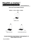
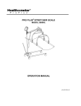
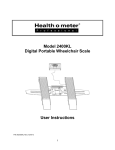
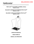
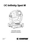
®
ProPlus Display Module
User Manual
Patents: US: 7550682B2, D508655; Europe: 0149984/1-8;
China: 200430004551.2, ZL200480031711X
Rev. 20091015
© Pelstar LLC 2009
User Manual
ProPlus® Display Module
www.homscales.com
Thank you for your purchase of this Health o meter® Professional product. Please read this
manual carefully and keep it handy for ready reference or training support.
TABLE OF CONTENTS
KEYPAD DESCRIPTION……..………………………………………………..3
CAUTION AND WARNING…………………………………………………….4
SPECIFICATIONS…………………...………………………………………….4
BATTERY INSTALLATION……………………………………………………..5
AC ADAPTER USE……………....……………………………………………..5
QUICK START INSTRUCTIONS……………………………………………...5
OPERATION INSTRUCTIONS….…………………………………………….7
MAINTENANCE……….……………………………………………………….18
EXPLODED DIAGRAM……………………………………………………….18
DISPLAY MODULE PARTS LIST……………………………………………19
CALIBRATION PROCEDURE………………………………………………..20
PC COMMUNICATION PROTOCOL………………………………………..20
WARRANTY AND SERVICE SUPPORT……………………………………24
2
KEYPAD DESCRIPTION
2700KL, 2650KL, 2600KL,
2500KL & 2101KL
2400KL
1100KL & 1600KL
Zeros the scale prior to weighing.
Allows repeated weighing of the patient
without stepping off the scale.
Holds the value of the weighed object on
the display until the button is pressed again
to clear the value. Also used to scroll down
in the menu.
Toggles between kilograms or
pounds. Also used to scroll up in the
menu.
Prompts entry of data to calculate
the patient’s Body Mass Index
(BMI).
Prints patient’s data (if printer is
connected to the scale).
Enters the menu of the scale.
Prompts entry of TARE value that
will be deducted from the weight on
the platform. Also releases tare
weight (returns display to zero).
Prompts entry of patient’s identification number (ID). This ID will be
stored with all the weighing made
until cleared or a different ID is
stored.
Used to enter commands and values
into the scale.
Reverts back one step when in the
menu and data entry modes.
Turns the scale ON and OFF.
2000KL
3
CAUTION AND WARNING
To prevent injury and damage to your display module, please follow these instructions very carefully.
• Do not use in the presence of flammable materials.
• Operating at other voltages and frequencies than specified could damage the equipment.
• If the “LOW BAT” indicator activates, for accurate weighing replace the batteries or connect the scale
to an AC power source as soon as possible.
• It is intended that this equipment be used with assistance of a healthcare worker.
SPECIFICATIONS
Health o meter® Professional ProPlus® Electronic Scales are highly sophisticated microprocessor technology. Each precision instrument is designed to provide accurate, reliable and repeatable weight measurements and features that make the weighing process simple, fast and convenient.
The scales are set up to use motion sensing technology, to determine the actual weight of a moving patient. The display settings may be changed to measure in live weight. See page 13 for instructions on
changing the display settings.
The weight can be displayed in pounds (decimal; fractions of a pound; lb/oz) or in kilograms.
The display unit can be operated using its AC adapter (included) or by 6-D cell batteries (not included).
DISPLAY SPECIFICATIONS
Capacity and Resolution
2700KL, 2650KL, 2600KL, 2500KL, & 2101KL
1,000 lb x 0.2 lb / 1/4 lb / 4 oz (454 kg x 0.1 kg)
2400KL
800 lb x 0.2 lb / 1/4 lb / 4 oz (360 kg x 0.1 kg)
1100KL & 1600KL
700 lb x 0.2 lb / 1/4 lb / 4oz (310 kg x 0.1 kg)
2000KL
400 lb x 0.2 lb / 1/4 lb / 4 oz (181 kb x 0.1 kg)
Power Requirements
Adapter model ADPT 31* (USA-CSA only)
120 VAC –9V DC 60Hz (Included) or 6 D cell
batteries (Not Included)
Adapter model ADPT 30* (Not Included) 120240 VAC— 9V DC 50-60 Hz
Environmental
Operating Temperatures:
50ºF to 95ºF (10ºC to 35ºC)
Storage Temperatures:
30ºF to 125ºF (0ºC to 50ºC)
Humidity:
85%
* Use only a Health o meter® Professional provided power supply.
4
BATTERY INSTALLATION / REPLACEMENT
Unplug the ProPlus® display from all power sources.
Using a Phillips screwdriver remove the battery cover from the display (A).
Disconnect battery holder cable connector from the scale-battery connector (B).
Carefully remove the battery holder by sliding it out of the display assembly (C).
Replace the batteries with new ones. *
Carefully position the battery holder into the display assembly.
Connect the battery holder cable connector to the scale-battery connector and carefully slide the battery holder into the display assembly.
8. Attach the battery cover to the display assembly and install the screw.
1.
2.
3.
4.
5.
6.
7.
* We recommend the use of EVEREADY Energizer® e2TM batteries.
AC ADAPTER USE
The ProPlus® display has been designed to operate on
9V DC and ships with an AC Adapter (APDT31). To
operate the display using the AC adapter, insert the
adapter into the jack located on the rear of the display.
Use only a Health o meter® Professional adapter with
the ProPlus® display.
POWER SUPPLY JACK
QUICK START INSTRUCTIONS
WEIGHING A PATIENT
1.
2.
3.
4.
Make sure there is no object on the weighing platform.
Press the ON/OFF button to turn the display on.
Wait until “000Lb00oz” and “ZERO” on the left side of the display appear.
Ask the patient to step on the scale. The display should read “WEIGHING” until the weight calculation is complete and the weight is displayed.
5. If you wish to reweigh without asking the patient to step off and on the scale again, press the REWEIGH button.
6. Ask the patient to step off the scale.
NOTE: The scale will always default to the settings and units last used.
WARNING: If the scale will not be used for a prolonged period of time, remove the batteries to avoid a
safety hazard.
5
QUICK START INSTRUCTIONS
TARE FUNCTION
When using the scale, the weight of an object such as a wheelchair or shoes accompanying the patient
can be subtracted from the total weight of the patient alone. The Tare function automatically performs this
subtraction, avoiding the need for manual calculations. ProPlus® scales allow tare weight to be entered
automatically (PUSH BUTTON TARE) or manually using the keypad to enter the exact tare value
(KEYPAD TARE).
AUTOMATIC (PUSH BUTTON) TARE
The user can set a tare value by pressing the TARE button (9) while there is a weight on the scale platform. The display will reset to zero and the word “TARE” will be displayed to indicate there is a tare value
stored in memory.
NOTE: Due to the scale’s sensitivity, we recommend using the REWEIGH function prior to setting the
TARE weight, in order to eliminate any operator interference with the item to be tared.
MANUAL (KEYBOARD / KEYPAD) TARE
1. Make sure there is no object on the weighing platform.
2. Press the ON/OFF button to turn the display on.
3. Wait until “000Lb00oz” and “ZERO” on the left side of the display appear.
4. Press the TARE button (9). The user will be prompted to enter the TARE value.
5. Use the keypad to enter the weight of the object desired to be tared (i.e. wheelchair) and press ENTER.
6. The value entered will be displayed as a negative value.
7. Place the patient and the tared object on the scale. The display will automatically deduct the entered
tared weight from the gross weight of the patient and tared object.
8. The weight of the patient will appear on the scale.
9. The tared value is stored in memory until it has been changed, cleared or the display has been turned
off.
Important: The TARE weight cannot exceed:
250lb (2101KL, 2500KL, 2600KL, 2650KL & 2700KL)
200lb (2400KL)
150lb (1100KL & 1600KL)
125lb (2000KL)
REMOVING THE TARE
Once a tare value has been stored and the word “TARE” appears on the display, the tare value can be
deleted from memory by pressing the TARE button. The scale will return to normal operation.
CALCULATING BMI
1. Complete steps 1 to 4 on page 6 for “Weighing a Patient”.
2. Press the BMI button (2).
3. The scale will prompt you to enter the patient’s height. Use the keypad to enter the height.
Note: When weighing in lbs., height is entered in ¼” increments. For the fractional portion of the
height, press 1 for ¼”, press 2 for ½” and 3 for ¾”. When weighing in kg the height is
entered in 1cm increments.
4. Press ENTER.
5. Display will show the patient’s BMI.
6. Press ENTER to return to normal weighing operation.
Note: The scale will not calculate a BMI for a patient 24 pounds (12 kg) or less. If a height is not
entered within 30 seconds of pressing the BMI key, the scale will return to normal operation.
6
OPERATION INSTRUCTIONS
MENU
In the menu screen the user can set preferences and/or instruct the scale how to handle stored data.
The menu can be navigated using the up and down keys (▲▼) or by entering the associated menu
position number with the keypad. The menu has a “roll-over” way of working: when the user scrolls to
the bottom of the menu and presses the down button, it will return to the top of the menu.
MENULOCK
NOTE: The default mode of the scale is set so the menu option is locked out. If the menu button is
pushed before activating the menu option, “MENULOCK” will show on the display. To temporarily
reactivate the use of the MENU key, press and hold the MENU key for 5 seconds. During the menu
access delay, the menu will display “MENULOCK”. After 5 seconds, the menu will show on the display
and you may begin navigating through the menu.
Main Menu
▲
→ 01-Weight Disp Mode
Indicator of menu position
02-Tare Weight
03-Data Management
Active menu option is
marked by inverted color
▼▲ to change
Scroll through the menu
options with ▲ and ▼ keys
▼
Enter
04-Scale Settings
05-System Settings
06-System Test
07-User Settings
08-Exit
01 WEIGHT DISPLAY MODE
(only applies to pound values, NOT metric values)
Before making changes to this scale setting, please refer to “Menu” instructions above to temporarily
activate the Menu key.
The user can set the screen display value in either fraction of pound (¼, ½ or ¾ lb), in pounds and
ounces (resolution of 4 ounces) or in decimals (resolution of 0.2 lb). When kg is selected as the units of
use, these settings have no effect. The mode that is selected is used through all the screens.
01-Display Mode
10/14/2009
▲
11:30pm
→ 01-Fraction Pounds
02-Pounds & Ounces
03-Decimals
▼▲ to change
185
▼
Enter
7
3
4 lb
OPERATION INSTRUCTIONS
01-Display Mode
10/14/2009
▲
11:30pm
01-Fraction Pounds
→ 02-Pounds & Ounces
03-Decimals
▼▲ to change
01-Display Mode
LB
10/14/2009
▲
01-Fraction Pounds
02-Pounds & Ounces
→ 03-Decimals
▼▲ to change
185 12
▼
Enter
OZ
11:30pm
185.8lb
▼
Enter
02 TARE WEIGHT
Before making changes to this scale setting, please refer to Menu instructions on page 7 to temporarily
activate the Menu key.
In addition to the two methods of entering tare values mentioned in the Quick Start Instructions, a tare
value can be stored into memory by selecting option 02-Tare Weight of the User Menu .
The Tare Weight window will appear and prompt the user to enter
the tare value using the numbered keypad and to press ENTER.
NOTE: The tare weight must be entered using the following increments: 4oz, 0.2lb, ¼ lb.
When the tared weight is not on the scale, the value entered will
be display as a negative value. After the TARE has been entered,
the scale goes back to normal operation. This TARE value is
stored in memory until changed, cleared or the scale is turned off.
If the tare weight is not entered in 30 seconds the scale will revert
back to normal operation, and the Menu Lock will be activated.
02-Tare Weight
005 12
LB
Exit
The word “TARE” appears on the display to
indicate a weight has
been tared. When the
tared wieght is removed
from the scale the value
will be displayed as a
negative value.
10/14/2009
OZ
Enter
11:30pm
TARE
-005 12
LB
8
Main Menu
▲
01-Weight Disp Mode
→ 02-Tare Weight
03-Data Management
▼▲ to change
▼
Enter
04-Scale Settings
05-System Settings
06-System Test
07-User Settings
08-Exit
The number that is to be changed will
flash and will move from the left to the
right after the appropriate number was
entered or by using the ▲ key (left) and
the ▼ key (right).
OPERATION INSTRUCTIONS
Removing the Tare
Once a tare value has been stored and the word “TARE” appears on the display, the tare value can be
deleted from memory by pressing the TARE button. The scale will return to normal operation.
03 DATA MANAGEMENT
Main Menu
▲
01-Weight Disp Mode
02-Tare Weight
→ 03-Data Management
▼▲ to change
▼
Enter
04-Scale Settings
05-System Settings
06-System Test
07-User Settings
08-Exit
Before making changes to this scale setting, please refer to the Menu instructions on page 7 to temporarily activate the Menu key.
The scale manages patient data including patient ID, weight, height, tare and BMI. The value is stored
in memory or transferred to a PC. This function is performed by opening a new data file.
OPEN A NEW DATA FILE:
1. Press the ID button (7) - See page 3 for the illustration.
2. Using the keypad, type in the identification number.
3. Press ENTER.
The scale offers two options to manage information: to transfer / download the values or to store them.
The first option automatically downloads (transferred) the value to your PC. The second option stores the
value in memory. The maximum capacity of the scale is 270 files of different data.
03-Data Management
▲
→ 01-Auto Download
02-Store In memory
03-Do not store data
▼▲ to change
▼
Enter
04-Transfer now
05-Clear memory
01 Auto-Download
01-Auto Download
Updated
Automatic Download is the default option and will transfer the value to the PC as soon as the patient steps off
the scale or when the user presses the HOLD/
RELEASE button if it was kept in “HOLD”. If no PC is
connected, the value is not transferred or stored and will
be lost after the load is removed from the scale.
9
OPERATION INSTRUCTIONS
02 Store in memory
The value is stored in memory
for later download to a PC. If the
memory is full the user will be
warned and given the option to
transfer all values to the PC or to
clear the memory of values.
02-Store In Memory
Updated
Memory FULL
▼
▼▲ to change
Enter
03 Do not store data
No data will be stored.
03-Do not store data
Updated
04 Transfer now
04-Transferring
0
10
All the values stored in memory are transferred to the PC
and the scale memory is cleared of all values. If the
transfer was unsuccessful, the values are kept in memory
until successfully transfer or cleared.
05 Clear memory
05-Clear mem?
Yes
▼▲ to change
No
If Yes is selected and Enter is pressed, all the values in
memory will be cleared. If No is selected, the display will
return to the last menu.
Enter
10
▲
8 positions left in memory
01-Transfer now
02-Clear memory
OPERATION INSTRUCTIONS
04 SCALE SETTINGS
Main Menu
02-Tare Weight
03-Data Management
→ 04-Scale Settings
▼▲ to change
04-Scale Settings
▲
▲
→ 01-Auto Hold
02-Sleep Time
03-Auto Off Time
▼
▼▲ to change
Enter
05-System Settings
06-System Test
07-User Settings
08-Exit
▼
Enter
04-Tone Volume
05-Disp Date & Time
06-Display Backlight
07-Display Contrast
08-Live Weight
09-Exit
Before making any changes to this scales settings, please refer to the Menu instructions on page 7 to
temporarily activate the Menu key.
01 Auto Hold Time
01-Auto Hold Time
00 Seconds
The user can determine how long to display the weight
reading once it is determined, regardless of whether the
patient remains on the platform. The scale defaults to no
Auto Hold Time. The maximum setting is 20 seconds
Hold Time.
Enter
02 Sleep Time
02-Sleep Time
01:00
Enter
The user can set the time elapsed
before the scale goes into the sleep
mode. The default is 1 minute.
When the scale goes into sleep
mode, STANDBY is displayed on
the screen. The maximum setting
is10 minutes Sleep Time.
STANDBY
03 Auto Off Time
03-Auto Off Time
10 Minutes
The user can determine how long the scale will operate
before turning off automatically due to inactivity. Default
time is 10 minutes. If the value is set to zero, the auto off
function is disabled. The maximum setting is 60 minutes
Auto Off Time.
Enter
11
OPERATION INSTRUCTIONS
04 Tone Volume
04-Tone Volume
▲
01-Keypad Tone
02-Stable Weight
03-Alarm Tone
▼▲ to change
▼
Enter
Set Volume
0
10
▼▲ to change
There is an option to adjust the beeping tone of the scale.
This tone should sound when the scale has determined
the weight on the platform, when a key is pressed, after
the scale is turned on, at the end of self-test, or in the case
of fault or warning.
Use the ▲ and▼ keys on the keypad to adjust the
volume. Whenever the user presses the key to change a
volume, a beep will sound to indicate the set volume
level.
Enter
05 Display Date and Time
05-Disp Date & Time
No
Yes
▼▲ to change
10/14/2009
ZERO
This option will turn on or turn off the
date and time display.
Enter
11:30pm
ZERO
000 00
LB
OZ
000 00
LB
OZ
06 Display Backlight
The user can set the brightness of the backlight.
06-Partial Display only
0
▼▲ to change
10
Enter
12
OPERATION INSTRUCTIONS
07 Display Contrast
The user can set the contrast of the LCD.
07-Display Contrast
0
10
▼▲ to change
Enter
By selecting “Yes” the user deactivates the motion-sensing
mode and activates the Live Weight mode. In Live Weight mode
the weight displayed will fluctuate with the patient’s movement.
In Live Weight mode the scale will not lock on to the weight as it
does when the motion-sensing mode is active.
08 Live Weight
08-Live Weight
Yes
No
▼▲ to change
To use motion sensing mode to verify a weight determined in the
Live Weight mode, press the REWEIGH button and the weight
will be displayed on the screen.
Enter
To deactivate Live Weighing mode, highlight “No” and press
enter.
05 SYSTEM SETTINGS
Main Menu
03-Data Management
04-Scale Settings
→ 05-System Settings
▼▲ to change
05-System Settings
▲
▲
→ 01-Set Time & Date
02-About
03-Display 24 Hour
▼
▼▲ to change
Enter
▼
Enter
06-System Test
07-User Settings
08-Exit
Before making any changes to this scales settings, please refer to the Menu instructions on page 7 to
temporarily activate the Menu key.
01 Set Time & Day
The user can set the time and date using the keypad.
05-System Settings
01-Set Time
▲
→ 01-Set Time & Date
02-About
03-Display 24 Hour
▼▲ to change
▲
→ 01-Set Time
02-Set Date
▼
▼
Enter
▼▲ to change
13
Enter
OPERATION INSTRUCTIONS
01 Set Time
02 Set Date
01-Set Time
02-Set Date
04:32:01
09/14/09
AM /PM
Enter
Enter
To set the time move between
hours, minutes and seconds using the up and down keys ▲▼
and enter the values on the keypad.
Set the date using the up and
down keys (▲▼) and enter the
values on the keypad.
02 About
05-System Settings
01-Set Time & Date
→ 02-About
03-Display 24 Hour
▼▲ to change
MCU Ver
:
Rev.1.2
MCU Ver
:
Rev.1.0
▲
This screen displays the
software version of the
display.
Last Updated: 04/12/09
▼
Enter
Exit
Enter
03 Display 24 Hour
05-System Settings
03-Display 24 Hour
▲
01-Set Time & Date
02-About
→ 03-Display 24 Hour
Yes
▼
▼▲ to change
Enter
No
There are two options to
display time in 12 hour
(AM/PM) or 24 hour format
Enter
10/19/2009
16:32
10/19/2009
0.0lb
04:32 pm
0.0lb
24-hour format
12-hour format
14
OPERATION INSTRUCTIONS
To display time in a 24 hour format, highlight “Yes” and press the ENTER button. The display will return
to the System Settings menu. If the 24 hour format was selected and the correct time was set in the 12
hour format, the display will automatically convert the time to the 24 hour format. Otherwise, the user
should select menu option 01-Set Time and Date to set the correct time for the 24 hour format.
05-System Settings
01-Set Time
▲
→ 01-Set Time & Date
02-About
03-Display 24 Hour
▼▲ to change
▲
→ 01-Set Time
02-Set Date
▼
▼
▼▲ to change
Enter
Enter
01-Set Time
16:32:01
Enter
06 SYSTEM TEST
Before making any changes to this scales settings, please refer to the Menu instructions on page 7 to
temporarily activate the Menu key.
Main Menu
▲
→ 01-Battery Test
04-Scale Settings
05-System Settings
→ 06-System Test
▼▲ to change
06-System Diagnostic
▲
02-UCB Connection
03-UI Test
▼
▼▲ to change
Enter
▼
Enter
07-User Settings
08-Exit
01 Battery Test
The display will show the estimated amount of battery life remaining
until the batteries will have to be replaced.
01-Battery Test
0
▼▲ to change
10
Enter
NOTE: In order to complete the battery test, the display must be
powered by batteries only. Unplug the display from AC power
source prior to battery test.
15
OPERATION INSTRUCTIONS
02 USB Connection
The display will test the connection to the PC and will show a message “Connection is OK” or “NO Connection”.
If “NO Connection” is shown, check your USB connections to the
display and your PC and retest the connection. Refer to qualified
service personnel if problem persists.
02-USB Connection
Connection
Is OK
Exit
03 Diagnostic Test
The display has a diagnostic routine where it tests the User Interface
(UI) hardware functionality (LCD, keypad). In order to do this the
user has to press all the keys according to the messages displayed
on the screen.
03-Diagnostic Test
Please Press
1 ...
Exit
Enter
03-Diagnostic Test
Please Press the
button marked 1 …
(you have 10 seconds)
Exit
If the requested command was not received or the wrong button was
pressed, the following message will be displayed.
Enter
If after 10 seconds the requested command was not received, the
following message will be displayed. If “UI Error Failure” is displayed, refer to qualified service personnel.
UI Error
Failure
07 USER SETTINGS
Before making any changes to this display’s settings, please refer to Menu instructions to temporarily
activate the Menu key.
Main Menu
05-System Settings
06-System Test
→ 07-User Settings
▼▲ to change
07-User Settings
▲
▲
→ 01-Retain Values
02-Disp Height & ID
03-Prompt For Height
▼
▼▲ to change
Enter
04-Prompt for ID
05-Exit
08-Exit
16
Enter
▼
OPERATION INSTRUCTIONS
01 Retain Entered Values
01-Retain Ent Values
No
Yes
▼▲ to change
Enter
This option allows the user to use the same values for ID, height and
TARE between weighing. If this option is disabled, the user has to
re-enter these values for each reading. If the values are not entered,
only the weight is stored.
NOTE: These values cannot be retained by ID number.
02 Display Height & ID
02-Disp Height & ID
Yes
No
▼▲ to change
10/14/2009
ZERO
Enter
11:30pm
10/14/2009
ZERO
0.0kg
11:30pm
0.0kg
Height: 170.0cm
ID: 9817237371
When the user selects to display the height and ID of the patient, it will be displayed at the bottom of the
screen. We recommend the use of this function to ensure that the patient’s correct ID and height have
been entered.
03 Prompt For Height
03-Prompt For Height
Yes
▼▲ to change
No
When this option is activated,
the user will be asked to enter
the patient’s height after every
weighing. The operator has 30
seconds to enter height.
10/14/2009
153
3
4
11:30pm
lb
Please enter Height:
0ft00 0/0in
▼▲ to change
Enter
Enter
04 Prompt For ID
04-Prompt for ID
Yes
▼▲ to change
No
When this option is activated,
the user will be asked to enter
the patient’s ID after every
weighing. The operator has 30
seconds to enter ID.
Enter
10/14/2009
153 34 lb
Please enter ID:
234587336
▼▲ to change
17
11:30pm
Enter
MAINTENACE
GENERAL
This section provides instructions for maintenance, cleaning, troubleshooting and operator replaceable
parts for ProPlus® Display Modules. Maintenance operations other than those described in this section
should be performed by qualified service personnel.
MAINTENANCE
Before first use and after periods of non-use. Check display for proper operation and function. If the display does not operate correctly. Refer to qualified service personnel.
1. Check overall appearance of the display for any obvious damage, wear and tear.
2. Inspect the AC Adapter for cord cracking or fraying or for broken or bent prongs.
3. See parts list on page 19 if replacement parts are required.
CLEANING
Proper care and cleaning is essential to ensure a long life of accurate and effective operation.
Disconnect the scale from the AC power source.
1. Clean all external surfaces with a clean damp cloth or tissue. Anti-bacterial soap and water may be
used. Dry with a clean soft cloth.
2. Do not immerse the display into cleaning or other liquid solution.
3. Do not use Isopropyl Alcohol or other cleaning solutions to clean the display.
4. Do not use abrasive cleaners.
EXPLODED DIAGRAM– DISPLAY MODULE
1
2
22
21
3
4
20
19
5
18
6
17
18
16
7
15
8
9
10
14
13
12
11
DISPLAY MODULE PARTS LIST
Key no.
Part no.
Description
Qty.
Remark
1
B411192
KEYPAD
1
1000 LB for 2700KL, 2650KL, 2600KL, 2500KL, & 2101KL
1
B3513101-0
KEYPAD
1
700LB for 1100KL & 1600KL
KEYPAD
1
800LB for 2400KL
B411220
KEYPAD
1
400LB for 2000KL
1
1
2
LENS, TRANSPARENT PC
1
BATTERY HOLDER. PP
1
4
STATIC PROTECTION MEMBRANE
1
5
LCD PCB ASM
1
6
WIRE
1
3
B2033801-0
7
PCB ASM
1
8
STATIC PROTECTION MEMBRANE
1
9
10
B3245801-0
11
12
B3822801-0
SINGLE FACE GLUE FOAM
1
INPUT/ OUTPUT POSTS LABEL
1
SCREW M3X6
2
BATTERY COVER, ABS (757)
1
13
SCREW M3.5X8
6
14
15
HEAD BACK, ABS+Q235A
SCREW, Ф 3X6
1
4
16
TERMINAL
1
17
SCREW, Ф 2.3 X 8
4
18
WIRE
1
19
POSITIVE PLATE
1
20
NEGATIVE PLATE
1
21
POSITIVE AND NEGATICE PLATE
1
22
HEAD FRONT, ABS+Q235-A
1
19
CALIBRATION PROCEDURE
All Health o meter® Professional scales are factory calibrated and do not require
calibration prior to use.
Calibration can be performed in kg or lb, according to the units of measure used upon entering into the calibration mode.
Operator Action
Display
1.
Make sure the display is turned off, then press and hold the HOLD/
RELEASE button while pressing the ON/OFF button.
Enter load weight:
450.0LB (or 200.0KG)
2.
Using the ▼ and ▲ keys and/or the numeric keypad set the
calibration weight to at least 1/2 of the capacity of the scale (for the
best results and greater accuracy, use the full capacity of the
scale).
Enter load weight:
450.0LB (or 200.0KG)
3.
Make sure there is nothing on the scale, then press ENTER button.
Zero calibration
Please clear the scale
4.
Please wait 1-3 seconds without touching or shaking the scale for
Zero Calibration to finish.
5.
Load the scale with the required weight and press the ENTER
button.
Weight calibration
Put: XXX.X
6.
Please wait 1-3 seconds without touching or shaking the scale for
Calibration to finish.
Weight calibration
Please wait
7.
If calibration is successful, the display will show Factor OK. If the
process failed, the display will show Factor Fail.
Factor Update
Factor OK! (or Factor Fail!)
8.
If successful, the display will begin to reboot.
9.
The display will return to the start up message.
Zero calibration
Please wait
Rebooting…
Please wait
Health o meter
Pro-Plus
10. Wait until the display resumes normal operation and then remove
the weight from the scale.
Health o meter
Pro-Plus
PC COMMUNCICATION PROTOCOL
This ProPlus® display uses an escape protocol for communicating with a PC and over the USB and
serial ports. In an Escape protocol, the escape (<esc> or ASCII 27) is used to indicate that there is a
command, and not data, following.
Two scenarios have been defined: Scale initiated communication and PC initiated communication.
The following is a table of what can be sent across the communications line.
Scale Initiated
PC Initiated
ESC Value
Send Single reading
ESC
Value
R
Update Firmware
U
Send continuous reading
R
Request current values/settings
Q
Send bulk readings
R
Diagnostics
A
Send Diagnostics
A
Send scale control messages
C
Request stored data
R
Set stored data
S
Delete stored data
X
20
PC COMMUNCICATION PROTOCOL
The following is a complete list of ESC characters that will be used:
Name
ESC
character
ESC value
with
parameters
Description
Reading
R
R
This will tell the PC that the scale is sending a reading. Immediately following
this will be the value that is sent (i.e.
<ESC>R<ESC>I1234567890<ESC>W200.00<ESC>Nm<ESC>…<ESC>E
ID
I
Icccccccccc
This is the patient ID. (10 chars)
Weight
W
Wnnn.nn
This is the patient weight (i.e. W200.05 means 200.5 )
Height
H
Hnnn.nn
This is the patient height
TARE
T
Tnnn.nn
This is the TARE weight that the scale is taring out
BMI
B
Bnnn.n
This is the patient's BMI
End Of Packet (EOP)
E
E
This indicates that the end of the command/datapacket has been reached
Units
N
Nc
Power Status
J
J
On
O
O
When prompted for a power status, this will indicate that the scale is turned on
This indicates in which unit the values have been taken (m=metric,
c=constitutional)
Requests the power status of the scale. The response to this will be either a
<ESC>O<ESC>E or <ESC>F<ESC>E or <ESC>L<ESC>E
Off
F
F
When prompted for a power status, this will indicate that the scale is turned off
(or is in low power/sleep mode) When in Low Power mode, the scale will return
L
DateTime
D
Dnnnnnnnnnnn
n
This is a time and date string (MMDDYYYYhhmmss)
This command has a parameter c, which will help doing the update of the firmware. First of all the PC will initiate the update by sending an Ur (Request for
update). The scale will reply with Uc (Clear to send) or Ue (error, don’t send).
Then the scale will send U127K or U127B (the length of the data that is following in Kbytes or Bytes) and send the data.
This is a request to receive scale global values such as brightness of LCD,
auto hold time, keypad beep volume, etc. (See Table A) (i.e. <ESC>QAHT will
return the Auto Hold Time of 10 seconds like this: <ESC>PAHT=10<ESC>E )
Update
U
Uc
Request
Q
Qccc
Response
P
Pccc=ccccccc
This will be the scales response to the request mentioned above
Diagnostics(1)
A
Accc
This is the request for a diagnostic test on certain parts of the scale (such as
battery life, loadcells, keypad, LCD etc.). (See Table B)
Diagnostics(2)
Z
Zccc
Control (set a value)
C
Cccc=cccccc
Get subject record
data and readings
G
G
This will return all the information from both the subject record data as well as
the readings stored in the readings table.
Set subject record data
S
S
This will set the subject record data for a specific patient. Immediately following
this will be the value that is set. (i.e.
<ESC>S<ESC>I1234<ESC>T200<ESC>Um<ESC>E will set the TARE for
patient ID1234 to 200kg)
Clear readings
X
X
This will clear all the values stored in the readings table on the scale. Only the
subject record data will not be deleted.
Clear subject record
data
Y
Y
This will clear the subject record data for a specific patient. The patient ID will
follow the Y immediately (<ESC>Iccccccccccc). If no ID is given, ALL the data
will be cleared.
This will be the response of the diagnostics done on the scale. Values will include error codes to indicate what is wrong with the scale, or all zeros to indicate that all is well.
This is to set the value of the scale's global settings such as backlight, auto
hold time, keypad beep volume etc. (See Table A) (i.e.
<ESC>CAHT=20<ESC>E will set the Auto Hold Time to 20 seconds)
We used descriptive characters to show the type of the parameters. These are: c=Character, n=Numeric. The number of parameters indicates the set
number of placeholders for these characters and numbers (i.e. Zccc indicates that a value containing 3 characters will be given.)
21
PC COMMUNCICATION PROTOCOL
Name of Control
Auto Hold Time
Auto Off Time
Identifier
AHT
AOT
Unit
nn (Seconds)
nn (Minutes)
Sleep Time
STM
nn (Seconds)
Keypad Volume
VKE
nn (01..10)
Stable weight Volume
VSW
nn (01..10)
Alarm Volume
VAL
nn (01..10)
Display of Date/Time
DAT
nn (01 or 10)
Backlight
BAC
nn (01..10)
Contrast
CON
nn (01..10)
Weight Display Mode (fractions(f), decimals(d) or Pounds and
ounces (p)
Tare Weight
WDM
c (f,d,p)
TAR
nnn.nn (Kg)
Unit Of Measure (Metric or constitutional)
UOM
c (m or c)
Positions left in RAM
RAM
nnnn (0..max)
Table A - Scale Global Values List and Identifiers
Name of component to test
Load Cell A
Load Cell B
Identifier
LCA
LCB
Error Code
E3A
E3B
Load Cell C
Load Cell D
LCC
LCD
E3C
E3D
Battery
BAT
PC Communication (USB)
PCC
E4L(Bat Low, but still usable) or
E4U (Bat Low and Unstable)
E05
Write to RAM
WRM
E08
Read from RAM
RRM
E09
Table B - Components to test
The different tables on the scale:
There will be two data tables on the scale. The first will store the subject record data (patient-related
data that does not change) and the second will store the data recorded during the readings made.
Subject record data
Fields: ID, TARE, HEIGHT
Readings
Fields: Index (referring to the ID from the Subject Record Table), Weight, Date-time
Sample and explanation of esc protocol
1. When the scale measures the weight of a patient and sends this over the communications line to the
PC, it will look like this:
Direction of communication
<SCALE>
<PC>
22
PC COMMUNCICATION PROTOCOL
2. When the PC requests the values of the stored records, it will look like this:
First the PC will ask the scale to send the data. We do this with the “Get Subject Record Data and Readings” command.
<SCALE>
Direction of communication
<PC>
Then the scale will reply with the stored data.
Direction of communication
<SCALE>
<PC>
If no data is stored on the scale, it will simply send
<ESC>R<ESC>E
23
PC COMMUNCICATION PROTOCOL
Pin Configuration for ProPlus® Cables
The pins of the two connectors are connected as follows:
RJ45
function
DB9
7
TX
2
5
RX
3
8
GND
5
1 2 3 4 5 6 7 8
RJ45
DB9
Transmission Parameters
Baud rate
9600
Parity
None
Databits
Stopbits
Startbits
Hardware handshake
8 bits
1bit
1 bit
None
WARRANTY AND SERVICE SUPPORT
For warranty information, terms and conditions please refer to the user manual accompanying your
specific Health o meter® ProPlus® model.
To get Warranty Service make sure you keep your sales receipt or document showing proof of purchase.
Call 1-800-638-3722 to receive a return authorization (RA) number, which must be included on the return
label. Attach your proof of purchase to your defective product along with your name, address, daytime
telephone number and description of the problem. Carefully package the product and send with shipping
and insurance prepaid to:
Pelstar, LLC
Attention R/A#_____________
Repair Department
11800 South Austin Avenue, Unit B
Alsip, IL 60803
If your scale is not covered by warranty, or has been damaged, an estimate of repair costs or
replacement costs will be provided to you for approval, prior to servicing or replacing.
Pelstar, LLC
11800 South Austin Avenue, Unit B • Alsip, IL 60803
1-800-638-3722 or 1-708-377-0600
PLEASE REGISTER YOUR SCALE FOR WARRANTY COVERAGE
AT: http://www.homscales.com/customers/registration.aspx
Health o meter® Professional products are manufactured, designed and owned by Pelstar, LLC.
ProPlus® is a registered trademark of Pelstar, LLC. Health o meter® is a registered trademark of Sunbeam Products, Inc. used under license.
© Pelstar, LLC 2009
24