1
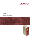
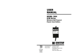
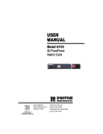
USER
MANUAL
MODEL 1030
and 1030S
Synchronous, Carrier
Controlled Short
Range Modem
Part #07M1030-C
Doc. #041013UC
Revised 4/20/98
CERTIFIED
An ISO-9001
Certified Company
SALES OFFICE
(301) 975-1000
TECHNICAL SUPPORT
(301) 975-1007
http://www.patton.com
1.0 WARRANTY INFORMATION
1.3 SERVICE
Patton Electronics warrants all Model 1030 components to be
free from defects, and will—at our option—repair or replace the product
should it fail within one year from the first date of shipment.
This warranty is limited to defects in workmanship or materials, and
does not cover customer damage, abuse or unauthorized modification.
If this product fails or does not perform as warranted, your sole
recourse shall be repair or replacement as described above. Under no
condition shall Patton Electronics be liable for any damages incurred
by the use of this product. These damages include, but are not limited
to, the following: lost profits, lost savings and incidental or
consequential damages arising from the use of or inability to use this
product. Patton Electronics specifically disclaims all other warranties,
expressed or implied, and the installation or use of this product shall be
deemed an acceptance of these terms by the user.
1.1 RADIO AND TV INTERFERENCE
The Model 1030 generates and uses radio frequency energy, and if
not installed and used properly—that is, in strict accordance with the
manufacturer’s instructions—may cause interference to radio and
television reception. The Model 1030 has been tested and found to
comply with the limits for a Class A computing device in accordance
with the specifications in Subpart J of Part 15 of FCC rules, which are
designed to provide reasonable protection from such interference in a
commercial installation. However, there is no guarantee that
interference will not occur in a particular installation. If the Model 1030
does cause interference to radio or television reception, which can be
determined by disconnecting the RS-232 interface, the user is
encouraged to try to correct the interference by one or more of the
following measures: moving the computing equipment away from the
receiver, re-orienting the receiving antenna and/or plugging the
receiving equipment into a different AC outlet (such that the computing
equipment and receiver are on different branches).
All warranty and nonwarranty repairs must be returned freight
prepaid and insured to Patton Electronics. All returns must have a
Return Materials Authorization number on the outside of the shipping
container. This number may be obtained from Patton Electronics
Technical Services at:
telephone: (301) 975-1007
email: [email protected]
web address: http://www.patton.com
NOTE: Packages received without an RMA number will not be
accepted.
Patton Electronics' technical staff is also available to answer any
questions that might arise concerning the installation or use of your
Patton Model 1030. Technical Service hours: 8AM to 5PM EST,
Monday through Friday.
1.2 CE NOTICE
The CE symbol on your Patton Electronics equipment indicates
that it is in compliance with the Electromagnetic Compatibility (EMC)
directive and the Low Voltage Directive (LVD) of the Union European
(EU). A Certificate of Compliance is available by contacting Technical
Services.
1
2
2.0 GENERAL INFORMATION
Thank you for your purchase of this Patton Electronics product.
This product has been thoroughly inspected and tested and is
warranted for One Year parts and labor. If any questions or problems
arise during installation or use of this product, please do not hesitate to
contact Patton Electronics Technical Support at (301) 975-1007.
3.0 CONFIGURATION
The Model 1030 provides seven configuration switches, which
allow selection of carrier control method, clocking method, RTS/CTS
delay and data rate. This section describes switch locations and
explains all possible switch configurations.
3.1 SWITCH LOCATIONS
2.1 FEATURES
Point-to-point or multipoint operation
Internal, external or receive loopback clocks (switch selected)
Data rates to 19,200 bps
Range to 11 miles
Carrier “on” or “controlled” (switch selected)
Options for easy daisy chain installation
Full or half duplex operation
Transformer isolated
Custom VLSI chip filters each data rate separately
Built-in Silicon Avalanche Diode surge protection
For your convenience, all configuration switches are located on a
SIP (single in-line package) mounted on the PC board. Figure 1 shows
the location of the SIP with respect to other PC board components. For
instructions on opening the Model 1030 case, see Section 4.1.2.
Terminal
Block
Patton
VLSI chip
PATTON
PE068
XXXX
•
•
•
•
•
•
•
•
•
•
Isolating
Transformers
Control
Switches
2.2 DESCRIPTION
The Patton Electronics Model 1030 synchronous, multipoint
short range modem provides exceptional versatility in a compact
package. Measuring only 2.66” x 2.10” x and 0.73”, the Model 1030 is
suitable for many applications where connection space is limited. The
Model 1030 supports up to twelve drops, and requires no AC power or
batteries for operation.
Operating at switch selectable data rates between 1.2 and 19.2
Kbps, the Model 1030 can attain distances between 3.5 and 8.5 miles
over two 24 AWG twisted pair (thicker gauges may yield better
distances). The Model 1030 operates half duplex or full duplex, and
accommodates three clocking methods: internal, external and received
loopback. Transformer isolation guards the Model 1030 against
ground looping in building-to-building applications. Other features
include a selectable RTS/CTS delay of 7 mSec or 53 mSec, and
selectable carrier status of constantly on or RTS controlled.
The Model 1030S is a surge protected version of the Model 1030
that uses Silicon Avalanche Diodes to provide 600 watts of transient
protection per wire.
3
Figure 1. Model 1030 PC board showing switches
Figure 2 shows the orientation of the switches on the SIP, including
ON/OFF position.
OFF
1
2
3
4
5
6
7
8
ON
Figure 2. Close up of configuration switches
4
3.2 SWITCH SETTINGS
Switch 5: RTS/CTS Delay
All possible settings for the Model 1030’s configuration switches
are presented in the summary table and descriptions below. If you
have additional questions regarding configuration, contact Patton
Technical Support at (301) 975-1007.
After request to send (RTS) is raised by the host terminal, the
Model 1030 raises CTS after a slight delay in order to give the remote
terminal time to receive an incoming signal. Depending on the type of
environment, either a 7mS or 53mS delay can be selected.
SWITCH SUMMARY TABLE
Position
Function
Factory Default
Switch 1
Not Used
Off
Switch 2
Carrier Enable
On
Switch 3
Transmit Clock
Off
Switch 4
Transmit Clock
On
Switch 5
RTS/CTS delay
On
Switch 6
Data Rate
On
Switch 7
Data Rate
Off
Switch 8
Data Rate
Off
Not Used
Switch 5
On
Off
Setting
7 mS (Default)
53 mS
Constant Carrier
}
Internal
Clock
7 mSec delay
}
9,600 bps
Switch 1: Not used
Switch 2: Carrier Enable
Switches 6, 7 and 8: Data Rate
Switches 6 thru 8 are set in combination to allow the Model 1030 to
be used at data rates from 1200 bps to 19,200 bps.
Switch 6
On
On
On
Off
On
Off
Off
Off
Switch 7
On
On
Off
On
Off
On
Off
Off
Switch 8
On
Off
On
On
Off
Off
On
Off
Switch 2 is used to specify how the carrier signal is raised. In most
point-to-point, full duplex applications, the carrier signal can remain
constantly “high”. In a multi-point environment, contention for the line is
“controlled” by RTS.
Switch 2
On
Off
Setting
Constant Carrier (Default)
Controlled by RTS
Switches 3 and 4: Transmit Clock
Switches 3 and 4 are used together to specify the clocking method.
The Model 1030 can provide an internal clock (Pin 15), receive an
external clock (from Pin 24), or loopback a received clock.
Switch 3
On
On
Off
Off
Switch 4
On
Off
On
Off
Setting
External Clock
External Clock
Internal Clock (Default)
Receive Loopback
5
6
Setting
1.2 Kbps
2.4 Kbps
4.8 Kbps
7.2 Kbps
9.6 Kbps (Default)
14.4 Kbps
19.2 Kbps
19.2 Kbps
4.0 INSTALLATION
Once the Model 1030 is properly configured, it is ready to connect
to your system. This section tells you how to properly connect the
Model 1030 to the twisted pair and RS-232 interfaces, and how to
operate the Model 1030.
When connecting two Model 1030s, it is necessary to use a
“crossover” cable. The diagram below shows how a crossover cable
should be constructed for an environment where both Model 1030s use
a 6-wire RJ-11 connector. Similar logic should be followed when using
RJ-45 connectors or a combination of the two.
4.1 CONNECTION TO THE TWISTED PAIR INTERFACE
SIGNAL
PIN#
COLOR
The Model 1030 supports data-only communication between two
RS-232 devices at distances to 11 miles and data rates to 19.2 Kbps.
There are two essential requirements for installing the Model 1030:
GND†
RCV◊
XMT
XMT
RCV
GND
1
2
3
4
5
6
Blue‡ ................White
Yellow ..............Red
Green...............Black
Red ..................Yellow
Black ................Green
White ...............Blue
1.
These units work in pairs. Therefore, you must have one Model
1030 at each end of a two twisted pair interface.
2.
To function properly, the Model 1030 needs two twisted pairs of
metallic wire. These pairs must be unconditioned, dry metallic
wire, between 19 and 26 AWG (the higher number gauges may
limit distance somewhat). Standard dial-up telephone circuits, or
leased circuits that run through signal equalization equipment, are
not acceptable.
For your convenience, the Model 1030 is available with three
different twisted pair interfaces: RJ-11 jack, RJ-45 jack and terminal
blocks with strain relief.
4.1.1 TWISTED PAIR CONNECTION USING RJ-11 OR RJ-45
The RJ-11 and RJ-45 connectors on the Model 1030’s twisted pair
interface are pre-wired for a standard TELCO wiring environment. The
signal/pin relationships are shown below:
RJ-11
SIGNAL
RJ-45
1...................GND†
2...................RCV‡
3...................XMT
4...................XMT
5...................RCV
6...................GND
†
‡
SIGNAL
1 .................N/C
2 .................GND†
3 .................RCV‡
4 .................XMT
5 .................XMT
6 .................RCV
7 .................GND
8 .................N/C
COLOR PIN#
GND
XMT
RCV
RCV
XMT
GND
Connection to ground is optional
Standard color codes—yours may be different
The Model 1030 is not sensitive to polarity
†
‡
◊
1 - Blue
2 - Orange
3 - Black
4 - Red
5 - Green
6 - Yellow
7 - Brown
8 - Slate
1 - Blue
2 - Yellow
3 - Green
4 - Red
5 - Black
6 - White
Standard AT&T color codes
4.1.2 TWISTED PAIR CONNECTION USING TERMINAL BLOCKS
If your application requires you to connect two pair of bare wires to
the Model 1030, you will need to open the case to access the terminal
blocks. The instructions on the following pages will tell you how to
open the case, connect the bare wires to the terminal blocks, and
fasten the strain relief collar in place so that the wires won’t pull loose.
Connection to ground is optional
The Model 1030 is not polarity sensitive
7
6
4
5
2
3
1
SIGNAL
8
1.
Open the unit by gently inserting a screwdriver between the
DB-25 connector and the lip of the plastic case (see below).
You don’t have to worry about breaking the plastic, but be
careful not to bend the D-sub connector.
4.
Connect one pair of wires to the two XMT (transmit) poles on
the terminal block. The Model 1030 is not polarity sensitive,
so either wire may connect to either pole.
5.
Connect the other pair of wires to the two RCV (receive) poles
on the terminal block. The Model 1030 is not polarity
sensitive, so either wire may connect to either pole.
Ultimately, you will want to construct a two pair crossover
cable that makes a connection with the two Model 1030s as
shown below:
XMT
XMT
G
RCV
RCV
6.
Once the unit has been opened, you will be able to see the
terminal blocks located at the rear of the PC board.
Strip the outer insulation from the twisted pairs about one inch
from the end.
3.
Strip back the insulation on each of the 2 twisted pair wires
about .25”.
9
}
One Pair
}
One Pair
If there is a shield around the telephone cable it may be
connected to “G” on the terminal block. To avoid ground
loops, we recommend connecting the shield at the computer
end only. A ground wire is not necessary for proper operation
of the Model 1030.
7. When you finish connecting the wires to the terminal block, the
assembly should resemble the diagram below:
RCV G XMT
2.
To Shield (Optional)
RCV
RCV
G
XMT
XMT
10
8.
Place the 2 halves of the strain relief assembly on either side
of the telephone wire and press together very lightly. Slide the
assembly so that it is about 2 inches from the terminal posts
and press together firmly. If your cable diameter is too small or
too large for our strain relief, please contact our technical
support. We have strain relief assemblies to accommodate
most cable diameters.
RCV G XMT
9.
10. Place the top half of the case as necessary to slide it over the
strain relief assembly. Do not snap the case together yet.
11. Insert one captive screw through a saddle washer. Then insert
the entire piece through the hole in the DB-25 end of the case.
Snap that side of the case closed. Repeat the process for the
other side. This completes cable installation.
Insert the strain relief assembly and wire into the slot in the
bottom half of the modem case and set it into the recess in the
case.
4.2 CONNECTION TO THE RS-232 INTERFACE
Once you have connected the twisted pair wires correctly, simply
plug the Model 1030 directly into the DB-25 port of the RS-232 device.
After doing so, remember to insert and tighten the two captive
connector screws.
4.2.1 CONNECTION TO A “DTE” DEVICE
RCV G XMT
The Model 1030 is wired as a DCE, and therefore wants to plug
into a DTE such as a terminal, PC or host. Because the Model 1030 is
interface powered, a direct connection to the RS-232 DTE port is most
desirable. If you must use a cable to connect the Model 1030 to the
DTE port, make sure it is a straight through cable of the shortest
possible length—we recommend 6 feet or less.
11
12
APPENDIX A
4.2.2 CONNECTION TO A “DCE” DEVICE
PATTON MODEL 1030/1030S SPECIFICATIONS
Since the Model 1030 is wired as a DCE, you cannot connect it
directly to another DCE such as a modem, multiplexer or printer. If you
need to connect the Model 1030 to another DCE device, you must use
a null modem cable wired according to diagram below. We recommend
that you use the shortest possible cable, preferably 6 feet or less.
Connection to Model 1030
DB-25 Pin No.
Connection to DCE Device
DB-25 Pin No.
†
1....................................................1
2....................................................3
3....................................................2
4....................................................8
8....................................................4
6..................................................20
20....................................................6
17..................................................24
24..................................................17
7....................................................7
Transmission Format:
Transmission Line:
Clocking:
Range:
Interfaces:
Data Rates:
Isolation:
Surge Protection:
Control Signals:
Connectors:
Power Supply:
Note: When connecting to another DCE device, the Model 1030
should be configured for “external clock” (see Section 3.2).
†
4.3 OPERATING THE MODEL 1030
Temperature Range:
Altitude:
Humidity:
Dimensions:
Weight:
Synchronous, full or half duplex
Two unconditioned twisted pair 19 - 26
AWG
Internal, external or receive loopback
(See table below)
EIA RS-232, CCITT V.24
1200 - 19.2 Kbps
Minimum 1500 V RMS via custom
transformers
600W Surge Protection (10x1000µs
waveform) (Model 1030S only)
CTS turns on 8 or 53 mS (switch selectable)
after the terminal raises RTS; carrier
continuous or controlled by RTS; DCD turns
on immediately after recognizing the
received signal from the line
DB-25 male or female on RS-232 side; RJ11, RJ-45 or terminal block with strain relief
on line side
No external power required, uses power
from EIA data and control signals
0-60°C (32-140°F)
0-15,000 feet
5 to 95% noncondensing
2.66” x 2.10” x 0.73”
2 oz.
Once the Model 1030 is properly configured and installed, it should
operate transparently—as if it were a standard cable connection.
Operating power is derived from the RS-232 data and control signals;
there is no “ON/OFF” switch. All data signals from the RS-232 interface
are passed straight through. In addition, one hardware control signal is
passed in either direction.
Model 1030 Distance Table (miles)
Data
Rate
19,200
9,600
4,800
2,400
1,200
13
19
7.5
10.0
10.0
10.0
11.0
14
Wire Gauge
24
3.5
3.5
7.0
8.5
8.5
26
2.5
2.5
4.0
5.0
6.0
APPENDIX B
PATTON MODEL 1030/1030S
RS-232 PIN CONFIGURATIONS
DIRECTION
“DCE” STANDARD SETTING
From Model 1030
Transmitting Timing - 15
From Model 1030
Receiver Timing - 17
To Model 1030
Data Term. Ready (DTR) - 20
To Model 1030
Transmitting Timing LXC - 24
1- (FG) Frame Ground
2- (TD) Transmit Data
3- (RD) Receive Data
4- (RTS) Request to Send
5- (CTS) Clear to Send
6- (DSR) Data Set Ready
7- (SG) Signal Ground
8- (DCD) Data Carrier Detect
Copyright © 1998
Patton Electronics Company
All Rights Reserved
15
DIRECTION
To Model 1030
From Model 1030
To Model 1030
From Model 1030
From Model 1030
From Model 1030