1
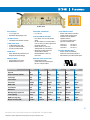
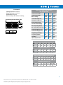
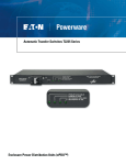
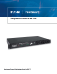
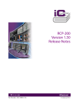
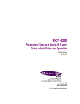
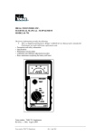
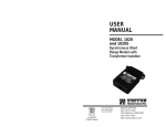
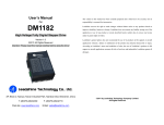
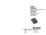
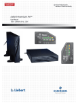
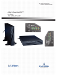
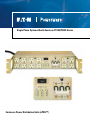
Single Phase Systems-North American PC125/PC420 Series
Enclosure Power Distribution Units (ePDU™)
PC125-C Front
RACK MOUNTED
• 19” x 3.4” (2U) x 8.5”.
• Approximate shipping weight: 19 lbs.
SPIKE/SURGE SUPPRESSION
• L-N, L-G, N-G
(3 N/O) REMOTE I/O PORTS
• Remote on/off and EPO control, EPO
overrides remote and local control
• Sequence Power Up additional
equipment down line
• “LT” units only: Latching remote (N/C) EPO, momentary start
LOCAL/OFF/REMOTE SWITCHING
• Local: Power “on or off” to the switched
outlets
• Off: When breaker is “on” but this switch is
in the “off” mode, you will have power to the
unswitched outlets only
• Remote: Power “on or off” to the
switched outlets via a remote device
• When using a Latching remote, the
selection switch is wired for
Remote/Off/Remote - There is no
local control
(12) NEMA OUTLETS
• 4 unswitched and 8 switched via remote
(4) INDICATOR LIGHTS
• (1) Main breaker power “ON”
• (1) Power to unswitched outlets
• (2) Power to switched outlets
POWER INPUT
• Power cable with plug is attached to unit
through the rear panel cable grip
EMI/RFI FILTERING
• Common Mode Line to Ground
• Differential Mode Line to Line
PC125-A-LT
PC125-A2-LT
PC125-B-LT
PC125-C-LT
PC125-D-LT
PC125-F-LT
MULTIPLE TIME DELAY(MTD)TM
• Section 1 powers on immediately
followed four seconds later by Section 2
• Select PC420 in part number for MTD option
OVERLOAD CIRCUIT PROTECTION
• Electromagnetic breaker
provides manual on/off switching and
trips in an overload condition
SPECIFICATIONS
PC125-A
PC125-A2
PC125-B
PC125-C
PC125-D
PC125-F
Approvals
UL
UL
UL
UL
UL
UL
Voltage Input/Output (50/60Hz)
120V~
120V~
240V~
120V~
120V~
240V~
Current Input
15A
20A
15A
30A
30A
30A
Current Output
12A
16A
12A
24A
24A
24A
Full Load VA
1440VA
1920VA
2880VA
2880VA
2880VA
5760VA
NEMA Outlets
5-15R
5-20R
6-15R
5-15R
5-20R
6-15R
Circuit Breaker
15A
20A
15/15A
15/15/30A
20/20/30A
15/15/30A
EMI/RFI Filter
20A
20A
20A
30A
30A
30A
Multi-Stage Surge Suppression
270V/150V
270V/150V
320V/270V
270V/150V
270V/150V
320V/270V
Cord/Length/Plug
14/3, 9’
12/3, 9’
14/3, 9’
10/3, 15’
10/3, 15’
10/3, 15’
NEMA Power Input Plug
5-15P
5-20P
N/A
L5-30P
L5-30P
L6-30P
Multiple Time Delay (MTD)
PC420-A
PC420-A2
PC420-B
PC420-C
PC420-D
PC420-F
2
www.pulizzi.com • [email protected] • 800-870-2248 • Fax: 605-334-4999
© 2008 Eaton Corporation. All Rights Reserved. All specifications are subject to change without notice.
Optional Remote Control Panel
RCP200-BLK-LT
RCP100-BLK-LT
Standard Remote Control Interface
REMOTE START REQUIRES (2) CONDITIONS:
1. The “on/off/remote” switch must be in the “remote” position.
2. A maintained closure between pins 1 & 3 will turn the unit on.
REMOTE POWER OFF REQUIRES (1) CONDITION:
1. Opening the maintained connection between pins 1 & 3 will
turn off the switched outlets.
REMOTE EPO REQUIRES (1) CONDITION:
1. A maintained contact between pins 2 & 3 will turn off
the switched outlets regardless of the position of the
“on/off/remote” switch.
SEQUENCED REMOTE:
Connect pins 1, 2 & 3 of the sequence port to pins 1, 2 & 3 on any remote
port of the slave unit. (Do not connect to another “sequence” port!)
The sequence port of the master unit activates 4 seconds after the final set
of outlets turn on. Additional units may be daisy chained in this fashion.
CAUTION!
THIS TYPE OF REMOTE IS NOT TO BE SUBSTITUTED
FOR A SAFETY INTERLOCK!
EPO is normally open, so removing the EPO connection
will not shut down the power to the unit.
Latching Remote “LT” Control Interface
REMOTE START REQUIRES (2) CONDITIONS:
1. A maintained contact between pins 2 & 3.
2. A momentary contact between pins 1 & 3.
REMOTE POWER OFF OR EPO REQUIRES (1) CONDITION:
1. Opening the maintained connection between pins 2 & 3.
Additional EPO or stop buttons can be connected in series
between pins 2 & 3.
This will turn off the switched outlets regardless of the
remote switch position.
SEQUENCE REMOTE:
Connect pins 1 & 2 of the “sequence” port to any remote port on
another “-LT” unit. The sequence port activates 4 seconds after the
final set of outlets turn on.
(Do not connect to another “sequence” port!)
NOTE: “LT” units are designed for remote operation only.
Even when the “REMOTE/OFF/LOCAL” switch is set to “LOCAL”,
the unit still requires a power request from the remote ports to
turn the unit on.
REMOTE OPERATION: Most Pulizzi® units have more than one remote connector. Unless labeled as “SEQUENCE” they are wired in parallel. Connection
to only one remote connector is required. It is recommended that a Pulizzi® control panel be ordered for use with your PDU. Connectors are provided for
those who wish to wire their own switches or control panels. We recommend using 14 AWG wire and not exceeding 50 feet for any remote cable. Mating
control panels can be seen on our web site at www.pulizzi.com.
If additional remote connectors are needed: The female AMP connectors used in our Power Controllers are: three pin - Part Number
1-480304-0 and four pin Part Number 1-480425-0, and are used with AMP Socket Terminals, Part Number 60619-1. The mating male AMP connector is:
three pin - Part Number 1-480305-0, and four pin - Part Number 1-480426-0 and are used with AMP male contacts Part Number 60620-1.
www.pulizzi.com • [email protected] • 800-870-2248 • Fax: 605-334-4999
© 2008 Eaton Corporation. All Rights Reserved. All specifications are subject to change without notice.
3
Environmental
Operating Temperature is 0 to 50 C
Storage Temperature is -40 to 70 C
Altitude Maximum 10,000 ft.
Relative Humidity is 95% Max Non-Condensing
Rack Mounting Hole Specification Table
19.00”
Y
Z A
HOLE SPECIFICATION TABLE
A
Y
Z
3.5
.875
1.75
TVSS (Transient Voltage Surge Suppression)
MOV SPECIFICATIONS
Continuous AC Voltage
150VAC
270VAC
320VAC
Continuous DC Voltage
200VDC
360VDC
420VDC
Max. DC Leakage
200µA
200µA
200µA
Low Varistor Voltage Limit
212VDC
389VDC
462VDC
High Varistor Voltage Limit
243VDC
453VDC
540VDC
Nominal Varistor Voltage
236VDC
424VDC
503VDC
Current For Varistor Voltage
1mA
1mA
1mA
Max. Clamp Voltage 8x20µs
360V
680V
810V
Max. Clamp Voltage Test Current 100A
100A
100A
Peak Current Rating (1 Pulse)
12000A
10000A
10000A
Peak Current Rating (2 Pulse)
9000A
6500A
6500A
Energy Rating (10x1000µs)
170J
325J
385J
Energy Rating (8x20µs)
170J
325J
385J
Capacitance
1700pF
970pF
820pF
Impulse Response Time
50ns
50ns
50ns
EMI/RFI FILTERING COMMON MODE INSERTION LOSS
Mhz.
.15
.50
1.0
5.0
10.0
30.0
dB.
6
19
28
42
45
50
DIFFERENTIAL INSERTION LOSS
Mhz.
.15
.50
1.0
5.0
10.0
30.0
dB.
6
6
30
50
30
30
EMI/RFI FILTERING COMMON MODE INSERTION LOSS
Mhz.
.1
.5
1.0
5.0
10.0
20.0
50.0
dB.
18
40
48
62
80
70
60
DIFFERENTIAL INSERTION LOSS
Mhz.
.1
.5
1.0
5.0
10.0
20.0
dB.
21
33
41
50
50
50
4
www.pulizzi.com • [email protected] • 800-870-2248 • Fax: 605-334-4999
© 2008 Eaton Corporation. All Rights Reserved. All specifications are subject to change without notice.
Drawings are not shown to scale
Dimensions are in inches
5
www.pulizzi.com • [email protected] • 800-870-2248 • Fax: 605-334-4999
© 2008 Eaton Corporation. All Rights Reserved. All specifications are subject to change without notice.