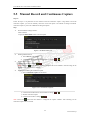
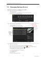
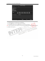
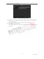
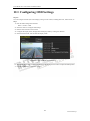
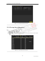
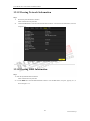
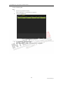
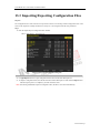
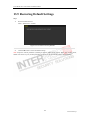
1
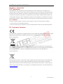
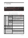
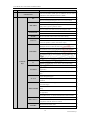
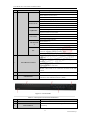
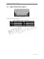
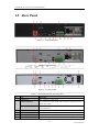
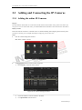
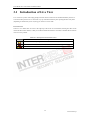
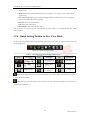
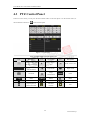
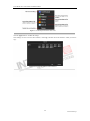
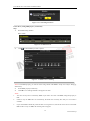
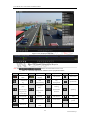
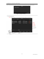
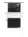
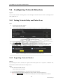
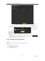
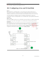
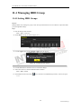
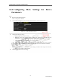
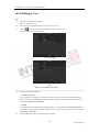
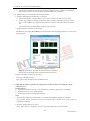
User Manual of I7- N07xx/N077xx/N08xx/N09xx
7
eSATA (Optional)
Connects external SATA HDD, DVD-R/W.
8
LAN Interface
Connectors for LAN (Local Area Network).
1 LAN interface provided for DS-7700NI-ST and 2 LAN interfaces for
DS-9600NI-ST/RT/XT and DS-8600NI-ST.
9
Termination Switch
RS-485 termination switch.
Up position is not terminated.
Down position is terminated with 120Ω resistance.
10
RS-485 Interface
Connector for RS-485 devices. T+ and T- pins connects to R+ and R-
Controller Port
D+, D- pin connects to Ta, Tb pin of controller. For cascading devices,
pins of PTZ receiver respectively.
the first NVR‟s D+, D- pin should be connected with the D+, D- pin of
the next NVR.
ALARM IN
Connector for alarm input.
ALARM OUT
Connector for alarm output.
11
GROUND
Ground(needs to be connected when NVR starts up).
12
AC 100V ~ 240V
AC 100V ~ 240V power supply.
13
POWER
Switch for turning on/off the device.
14
USB interface
Universal Serial Bus (USB) ports for additional devices such as USB
mouse and USB Hard Disk Drive (HDD).
Figure 1. 9 I7-N07xxVH
Table 1. 8 Description of Rear Panel Interfaces
No.
Item
Description
1
VIDEO OUT
BNC connector for video output.
AUDIO OUT
BNC connector for audio output.
3
AUDIO IN
BNC connector for audio input. (Also for voice talk)
4
RS-232 Interface
Connector for RS-232 devices.
5
VGA
DB9 connector for VGA output. Display local video output and menu.
6
HDMI
HDMI video output connector.
7
USB
Connects USB disks and devices.
8
LAN Interface
Connector for LAN (Local Area Network).
RS-485 Interface
Connector for RS-485 devices. T+ and T- pins connect to R+ and R- pins of
2
9
PTZ receiver respectively.
ALARM IN
Connector for alarm input.
ALARM OUT
Connector for alarm output.
10
Power Supply
12VDC power supply.
11
Power Switch
Switch for turning on/off the device.
25
www.internec.pl