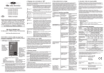
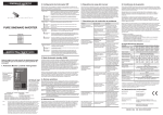
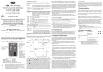
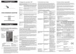
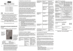
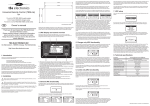
1
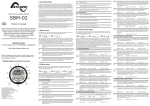
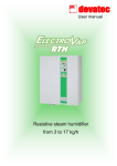
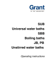
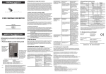
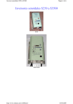
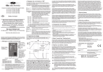
2. Dipswitch settings
6. Inverter load requirements
8. Warranty conditions
During step 5 of the installation sequence, you can alter the factory settings of the
dipswitches to change the inverter’s functionality on a few points. The following settings
can be made :
Before you connect your appliance(s) to the inverter, always check it's maximum power
consumption. Do not connect appliances to the inverter needing more than the nominal
power rating of the inverter continuously. Some appliances like motors or pumps, draw
large inrush currents in a startup situation. In these conditions, it is possible that the
startup current exceeds the overcurrent trip level of the inverter. In this case the output
voltage will shortly decrease to limit the output current of the inverter. If this overcurrent trip
level is continuously exceeded, the inverter will shut down and restart within 20 seconds.
In this case it is advisable to disconnect this appliance from the inverter, since it requires to
much power to be driven by this inverter. The inverter will not restart automatically when it
has shut down due to overloads for four times in a row. In this case, the inverter needs to
be restarted manually. Note that at higher ambient temperature levels, the overload
capacity of the inverter reduces.
TBS Electronics (TBS) warrants this inverter to be free from defects in workmanship or
materials for 24 months from the date of purchase. During this period TBS will repair the
defective inverter free of charge. TBS is not responsible for any costs of the transport of
this inverter.
1. LOC. / EXT.
Professional DC to AC sinewave inverter
powersine PS1000-12
powersine PS1400-24
powersine PS1600-12
powersine PS1800-24
powersine PS1800-48
: Choose output frequency (dipswitch 2) and low battery protect
(dipswitch 3) settings to be made using the local dipswitches, or
override these settings and setup the inverter using the optional
Universal Remote Control.
on
1
on
Setting ON : The local dipswitch settings of dipswitch 2 and 3 are ignored and
configuration must be done using the Universal Remote Control.
Setting OFF : The local dipswitch settings are used (factory default).
1
2. 50Hz / 60Hz
: Choose 50Hz or 60Hz output frequency.
on
Setting ON : Output frequency is 60Hz (factory default for 115V outputs).
2
on
Setting OFF : Output frequency is 50Hz (factory default for 230V outputs).
Owner’s manual
EN
7. Troubleshooting guideline
Problem
Possible cause
Remedy
Inverter is not working (all
indicators are off).
Power switch in OFF (0)
position.
Push the power switch in the
ON (I) or ASB (II) position.
Poor contact between the
inverter's battery wires and
the battery terminals.
Clean battery terminals or
inverter wire contacts.
Tighten battery terminal
screws.
2
3. LOW BATT
PROTECT
: Chooses whether the inverter will shut down at a safe low voltage
level for the battery, or at an even lower voltage level.
on
Thank you for purchasing a TBS Electronics DC to
AC sinewave inverter.
Please read this owner’s manual for information
about using the product correctly and safely.
Keep this owner’s manual close to the inverter for
future reference.
Setting ON
3
on
3
: the inverter will shutdown at a safe low voltage level to avoid a too
deep discharge of your battery. This voltage level is typically
around 10.5V for 12V inverters, 21V for 24V inverters and 41V for
48V inverters. (factory default).
Setting OFF : the inverter will shutdown at a lower battery voltage level. This
setting is only advised for professional users that are fully aware of
the battery system's capabilities. TBS is not responsible for any
battery damage or battery cycle loss caused by misuse of this
setting. The low voltage levels in this setting are typically 9V
for 12V inverters, 18V for 24V inverters and 36V for 48V inverters.
'Battery voltage too low or
too high' error keeps on
appearing.
4. BYPASS REMOTE : Bypasses the remote switch connection when no remote switch is
SW.
connected.
Blown inverter fuse.
The inverter has to be
returned for service.
Very poor battery condition.
Replace battery.
Poor battery condition.
Replace battery or charge it
first.
Poor connection or
inadequate wiring between
battery and inverter,
resulting in too much
voltage drop.
When extending the battery
wires of the inverter make
sure you use the correct wire
gauge (1.5 times larger than
the fixed battery wires). It's
not advisable to extend the
battery wires to more than 3
meters.
on
TBS ELECTRONICS BV
De Marowijne 3, 1689AR, Zwaag, The Netherlands
http://www.tbs-electronics.com
Setting ON
: remote switch connection terminals are bypassed (factory setting).
4
on
Setting OFF
4
: remote switch connection terminals are open. A remote switch
must be connected and switched ON in order to activate the
inverter. The local on/off switch on the frontpanel always overrides
the remote switch. So in order to use the remote switch, the local
on/off switch must be in the 'on' or 'auto standby' (ASB) position.
General failure in your
electrical system (in case of
no direct battery
connection).
Too high ripple voltage on
DC input.
3. Automatic standby (ASB) mode
Before proceeding with this owner’s manual, please make
sure you have carefully read the installation guide on the
backside of this paper!
1. Powersine display and control overview
powersine
output power bar
100%
75%
50%
“power on, off, ASB”
switch
5%
auto standby
When in position “O” the
inverter if off.
When switched to “I” the
inverter switches on in
normal operating mode.
When switched to “II” the
inverter operates in Auto
StandBy (ASB) mode.
See chapter 3 for more
details on the ASB mode.
“inverter on” or “error” indicator
To warn you before the inverter might shut down, the inverter is equipped with an
acoustical alarm. There are three kinds of acoustical alarms depending on the cause of
possible inverter shutdown. These alarms are related to the red LED blinking
sequences mentioned in chapter 1. The following acoustical alarms are available :
Alarm 1 : One beep per second. The battery voltage has reached a too low or too high
level. If the battery voltage respectively decreases or increases any further, the
inverter shuts down.
Alarm 2 : Two beeps per second. The inverter will shut down soon due to an
overloaded output. Note that at heavy overloads the alarm will not sound due
to too fast inverter shut down.
indicator mode :
description :
Alarm 3 : Three beeps per second. The inverter will shut down when it's
temperature is rising another three degrees Celsius.
continuous green
flashing green
flashing red (1 flash per sec.)
flashing red (2 flashes per sec.)
flashing red (3 flashes per sec.)
power on, normal operation
power on, ASB activated
DC error (see note 1)
output overload or short circuit
high temperature error
5. Alarm relay
DC errors are too low or too high battery voltage and too high input ripple voltage. A
ripple voltage error can be caused by a too small battery, too long battery cables, bad DC
connections or too small battery cable wire gauge.
Operating in DC error mode, the inverter restarts automatically when the battery voltage
returns to the normal inverter input voltage range again. If the DC error is caused by an
input ripple voltage error, the inverter needs to be restarted manually. Operating in output
overload or short circuit error, the inverter automatically restarts after 20 seconds.
Operating in high temperature error, the inverter restarts automatically when the inverter
temperature has reached a normal temperature level again. All error types are allowed
maximal four times in a row within a certain time period. When more than four errors are
counted within this time period, the inverter remains operating in an error mode and
needs to be restarted manually.
This inverter is equipped with a potential free alarm relay. This relay will be activated when
the inverter shuts down and jumps to an error mode as described in chapter 1. The alarm
relay de-activates again when the error mode has been cleared and the inverter is running
in normal operating mode again. On pins 1,2 and 3 of the 5 pins screw terminal located in
the connection compartment, both normally closed and normally open contacts are
available. Please make sure not to exceed the maximum relay contact rating of 60V and
1A to avoid damaging the relay.
Check battery wire
connections. Decrease
battery wire length. Increase
battery size. Make sure that
no other equipment on the
same battery is generating a
high ripple voltage.
Make sure that the total
power rating of the
connected equipment is
lower than the nominal
inverter power rating.
This warranty will not apply where the product has been misused, neglected, improperly
installed or repaired by anyone other than TBS. TBS is not responsible for any loss,
damage or costs arising from improper use, use in an unsuitable environment, improper
installing of the inverter and inverter malfunctioning.
Since TBS cannot control the use and installation (according to local regulations) of their
products, the customer is always responsible for the actual use of these products. TBS
products are not designed for use as cricital components in life support devices or
systems, that can potentially harm humans and/or the environment. The customer is
always responsible when implementing TBS products in these kind of applications. TBS
does not accept any responsibility for any violation of patents or other rights of third
parties, resulting from the use of the TBS product. TBS keeps the right to change product
specifications without previous notice.
1)
Examples of improper use are :
- Too high input voltage applied
- Reverse connection of battery polarity
- Mechanical stressed enclosure or internals due to harsh handling and/or incorrect
packaging
- Backfeed via inverter output from external power source like public grid or generator
- Contact with any liquids or oxidation caused by condensation
9. Technical specifications
Parameter
Output power
1)
PS1000-12
PS1400-24
PS1600-12
PS1800-24
PS1800-48
Pnom
850VA
1000VA
1300VA
1400VA
1400VA
P10min
1050VA
1450VA
1600VA
1800VA
1800VA
Psurge
2000VA
2800VA
2500VA
3000VA
3000VA
230VAC±2% or 115V±2% (True sinewave)
Output voltage
Output frequency
50Hz±0.05% or 60Hz±0.05%
All loads are accepted
Admissible cosö of load
Input voltage (±3%)
Nom.
Range
12V
24V
12V
‘High temperature error’
keeps on appearing.
Note : Do not turn off the
inverter when it's operating
in an ‘High temperature
error’. The inverter needs
this error time to cool down.
Make sure that the
connected equipment is not
broken or malfunctioning.
Check if the AC power cord
between the inverter and the
connected equipment is ok.
Any physical damage on the
power cord can produce a
short circuit.
Connected equipment
causes a too large inrush
current.
Try to power-up connected
equipment successively, and
not simultaneously.
Otherwise stop using the
connected load, it's not
suitable to power it with this
inverter.
Airflow around the inverter
is obstructed.
Make sure there is at least
10 centimeters of clearance
around the inverter. Remove
any items placed on or over
the inverter. Keep the
inverter away from direct
sunlight or heat producing
equipment.
Too high ambient
temperature.
Move the inverter to a cooler
environment or provide
additional cooling by an
external fan.
48V
24V
10.52) - 16V 212) - 31V 10.52) - 16V 212) - 31V
412) - 60V
92%
92%
92%
92%
96%
Noload power consumption3)
< 9.6W
< 12W
< 9.6W
< 12W
< 12W
[ASB]
[2.5W]
[3.5W]
[2.5W]
[3.5W]
[4.7W]
Maximum efficiency
Operating temperature range
ASB Threshold
-20°C to +50°C
Pout = 10W
Short circuit, overload, high temperature, AC backfeed,
high/low battery voltage and high input ripple voltage
Protections against
2 x 1.5 meter, 25mm2
DC input connection
2 x 1.5 meter, 35mm2
25mm2
Screw terminals
AC output connection
4. Acoustical alarms
inverter on
note 2 :
Inverter is overloaded.
Connected equipment
causes a short circuit at the
inverter's output.
25%
power on
note 1 :
'Output overload or short
circuit' error keeps on
appearing.
Note that some loads like TV/video equipment (with standby mode) and alarm clocks need
continuous power so that the ASB mode can not be used. With some small non
compensated loads, it is possible that the inverter jumps from continuous output to pulsed
output and vice versa all the time. In this case you will have to connect a small additional
load to the AC output.
1600VA 12VOLT
indicates the percentage of delivered output power. The power
bar turns red if more
than nominal output
power is presently
being delivered.
When the inverter is not supplying power to an appliance for a longer time, it is
recommended to use the inverter in the "Auto Standby" (ASB) mode to heavily reduce the
inverter's own power consumption. In this case the power switch must be pushed in the
“II” position. In the ASB mode the inverter will generate a testpulse on it's output once per
second, to check if there is a load applied. When a load is connected to the inverter output
(or switched on) drawing more than approx. 10W, the inverter jumps to the continuous
mode immediately, delivering power to the load. When the load is disconnected again (or
switched off), after 4 seconds the inverter jumps back to the pulsed output ASB mode. This
way the inverter automatically jumps to a low power mode when there is no power
demand on the output.
Check your electrical system
or consult an electrical
engineer to check it for you.
This warranty is void if the inverter has suffered any physical damage or alteration, either
internally or externally, and does not cover damage arising from improper use1),
attempting to operate the inverter with excessive power consumption requirements, or
from use in an unsuitable environment.
351 x 210 x 114mm
Enclosure size (L x W x H)
Total weight
10.5kg
Protection class
The inverter complies with the
following standards
IP21 (vertical mounting)
EN61000-6-3 (EN55022), EN61000-6-2 (EN61000-2/3/4,
EN61000-4-3), LVD 73/23/EEC (EN60335-1)
Note: the given specifications are subject to change without notice.
1)
Measured with resistive load at 25°C ambient. Power ratings are subject to a tolerance of 4% and are
decreasing as temperature rises with a rate of approx. 1.2%/°C starting from 25°C.
2)
Undervoltage limit is dynamic. This limit decreases with increasing load to compensate the voltage drop
across cables and connections.
3)
Measured at nominal input voltage and 25°C.
10. Declaration of conformity
MANUFACTURER
:
TBS Electronics BV
ADDRESS
:
De Marowijne 3
1689 AR Zwaag
The Netherlands
Declares that the following products :
PRODUCT TYPE
MODELS
:
:
DC to AC Sinewave inverter
PS1000-12, PS1400-24, PS1600-12, PS1800-24,
PS1800-48
Conforms to the requirements of the following Directives of the European Union :
EMC Directive 2004/108/EC
RoHS Directive 2002/95/EC
The above product is in conformity with the following harmonized standards :
EN61000-6-3: 2001
EMC - Generic Emissions Standard
EN61000-6-2: 2005
EMC - Generic Immunity Standard
GB
INSTALLATION GUIDE
- Please read this document very carefully to avoid inverter malfunction, shock and/or fire hazards!
- This document provides a brief overview of a stand alone inverter installation. For long term safe and troublefree operation, it is very important to read the owner’s manual on the rear side of this paper as well!
- Please follow the exact installation sequence as given below. Skipping one or more steps could result in inverter malfunctioning or shock and/or fire hazards!
1 UNPACKING
The inverter package should contain the
following items :
2a LOCATION REQUIREMENTS
3 INVERTER MOUNTING
= Approved
4 CONNECTION PRECAUTIONS
= Not recommended
Prior to inverter mounting, please make sure that the mounting location meets the following requirements :
Before making any electrical connections to your inverter, carefully read
all safety instructions below!
- Install the inverter in a well ventilated room.
- Inverter (incl. DC cables).
WARNING
- Avoid any contact with water or other liquids on the inverter. Do not expose the inverter to rain or moisture.
- Make sure that your complete inverter installation including all AC and DC
connections, are in accordance to all locally applicable regulations.
- This Installation guide / Owner's manual.
- 2x M10 crimp terminals.
- Do not place the unit in direct sunlight or other high temperature environments. Ambient air temperature should be between 0°C
and 40°C (humidity < 95% non condensing). Note that in some extreme situations the inverter's case temperature can exceed
70°C.
- Operation of your inverter without proper grounding may lead to hazardous
situations. Use the inverter chassis ground terminal between the fans, to connect
to your central ground (vehicle chassis, grounding system of your boat etc.).
- 4x Mounting screws.
After unpacking, check if the inverter
shows any mechanical damage. Never
use the inverter when the unit is
damaged, contact your local supplier for
further information.
- Do not obstruct the airflow around the inverter. Leave at least 10 centimeters clearance around the inverter. Do not place items
on or over the inverter while it's operating. When the inverter is running to hot, it will shut down until a safe temperature level is
reached to restart the inverter.
- This inverter has a floating AC output. The neutral (N) output should be connected
to chassis ground (PE) to ensure proper functioning of a GFCI (Ground Fault
Circuit Interrupter). Please check your local regulations for further details.
- Never use the inverter at locations where there is gas or explosion danger.
- Do not expose the inverter to dusty environments.
- Do not install the inverter directly above the batteries. Battery gasses can cause explosions and have corrosive properties which
may cause damage to the inverter.
vertical wall mounting
(IP21)
vertical wall mounting
(upside down)
horizontal wall mounting
187mm
- To avoid inverter damage, always check if your battery voltage corresponds to the
input voltage range of your inverter.
2b BATTERY PRECAUTIONS
- Always install a DC fuse inline with the battery positive (+) cable, as near as
possible to the battery.
334mm
- Working in vicinity of a lead acid battery is dangerous. Batteries can generate explosive gases during operation. Never smoke or
allow a spark or flame in vicinity of a battery. Provide sufficient ventilation around the battery.
- Wear eye and clothing protection. Avoid touching eyes while working near batteries. Wash your hands when done.
- If battery acid contacts skin or clothing, wash immediately with soap and water. If acid enters eye, immediately flood eye with
running cold water for at least 15 minutes and get medical attention immediately.
- Be careful when using metal tools in vicinity of batteries. Dropping a metal tool onto a battery might cause a shorted battery and
an explosion.
floor mounting
- Make sure to connect the battery to the inverter using the correct polarity. The
red DC cable must be connected to the positive (+) terminal, and the black DC
cable to the negative (-) terminal of the battery. Exchanging these cables will
damage the inverter permanently. This damage is not covered by the warranty.
- Never connect the inverter's AC output to an external AC source. This may
damage the inverter.
ceiling mounting
- Remove personal metal items such as rings, bracelets, necklaces, and watches when working with a battery. A battery can
produce a short circuit current high enough to weld a ring or the like to metal, causing severe burns.
5 MAKING AC OUTPUT AND CONTROL CONNECTIONS
- Never remove the connection compartment panel when the battery is still
connected to your inverter. Before removing the panel for service, always
disconnect the battery and activate the inverter (power switch in position I) for at
least 10 seconds to discharge all internal capacitors. This procedure should also
be followed prior to transporting your inverter.
126mm
drilling template
6 MAKING DC INPUT CONNECTIONS
inverter fuse
1)
1A/60V
max.
AC out
L1 PE N
TBSLink
dipswitch
For explanation on the dipswitch settings,
please consult the owner’s manual on the
rear side of this paper (chapter 2).
WARNING
1)
+
Access the connection compartment
by removing the two screws and
sliding the red cover downwards.
This inverter has a floating AC
output. The neutral (N) output
should be connected to chassis
L1
ground (PE) to ensure proper
PE
functioning of a GFCI (Ground
N
Fault Circuit Interrupter). Please
Use a wire size of
note that in some countries a GFCI
2
Ø1.5mm (AWG15) or
only, is not considered safe
larger for the AC wires
enough. Always check your local
regulations for further details.
Please try to avoid extending the battery cables. If
unavoidable, use at least 1.5 times the wire gauge as
supplied with the inverter. Maximum recommended
battery cable length is 3 meters (10 feet).
Before connecting the battery, slide
the red connection compartment
cover to it’s original position again
and relocate the two screws.
1)
Battery fuse ratings
PS1000-12 model : 200A/32V
PS1400-24 model : 120A/32V
PS1600-12 model : 300A/32V
PS1800-24 model : 150A/32V
PS1800-48 model : 80A/80V
Do not connect
the battery
cables yet!
chassis
ground
Red cable
Black cable
max. length 50m (150ft)
Fuse1)
Remote on/off
switch
use Ø1mm2 (AWG17) wire size
+60V max.
1A fuse
Nominal battery voltage
PS1000-12 / PS1600-12 model : 12V
PS1400-24 / PS1800-24 model : 24V
PS1800-48 model : 48V
Alarm indicator light (1A max.)
Universal Remote Control (optional)
- (return)
WARNING
PS1000-1800 Manual Rev3e / Printed in The Netherlands
Double check for correct
polarity, before connecting the
battery cables to the battery!
Recommended capacity
PS1000-12 model : ³ 160Ah
PS1400-24 model : ³ 90Ah
PS1600-12 model : ³ 200Ah
PS1800-24 model : ³ 120Ah
PS1800-48 model : ³ 60Ah