1
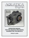
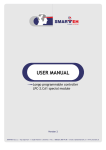
USER MANUAL
Longo programmable controller
LPC-2.DU1 LCD control panel
Version 2
SMARTEH d.o.o. / Trg tigrovcev 1 / 5220 Tolmin / Slovenia / Tel.: +386(0)5 388 44 00 / e-mail: [email protected] / www.smarteh.si
Longo programmable controller LPC-2.DU1 LCD control panel
Written by SMARTEH d.o.o.
Copyright © 2012, SMARTEH d.o.o.
User Manual
Document Version: 002
July 1, 2012
i
Longo programmable controller LPC-2.DU1 LCD control panel
STANDARDS
AND
PROVISIONS:
Standards,
recommendations,
regulations and provisions of the country in which the devices will
operate, must be considered while planning and setting up electrical
devices. Work on 230 VAC network is allowed for authorized personnel
only.
DANGER WARNINGS: Devices or modules must be protected from
moisture, dirt and damage during transport, storing and operation.
WARRANTY CONDITIONS: For all modules LONGO LPC-2 – if no
modifications are performed upon and are correctly connected by
authorized personnel – in consideration of maximum allowed
connecting power, we offer warranty for 24 months from date of sale
to end buyer. In case of claims within warranty time, which are based
on material malfunctions the producer offers free replacement. The
method of return of malfunctioned module, together with description,
can be arranged with our authorized representative. Warranty does
not include damage due to transport or because of unconsidered
corresponding regulations of the country, where the module is
installed.
This device must be connected properly by the provided connection
scheme in this manual. Misconnections may result in device damage,
fire or personal injury.
Hazardous voltage in the device can cause electric shock and may
result in personal injury or death.
NEVER SERVICE THIS PRODUCT YOURSELF!
This device must not be installed in the systems critical for life (e.g.
medical devices, aircrafts, etc.).
If the device is used in a manner not specified by the manufacturer,
the degree of protection provided by the equipment may be impaired.
Waste electrical and electronic equipment (WEEE) must be collected
separately!
LONGO LPC-2 complies to the following standards:
• EMC:EN 61000-6-2 (EN 50082), EN 61000-6-4 (EN 50081)
• LVD: IEC 61131-2
• Vibrations and climatic-mechanical: EN 60068-2-6, EN 60068-2-27,
EN 60068-2-29
Smarteh d.o.o. operates a policy of continuous development.
Therefore we reserve the right to make changes and improvements to
any of the products described in this manual without any prior notice.
MANUFACTURER:
SMARTEH d.o.o.
Trg tigrovcev 1
5220 Tolmin
Slovenia
ii
Longo programmable controller LPC-2.DU1 LCD control panel
LPC-2.DU1 LCD control panel
1 DESCRIPTION...................................................................................1
2 FEATURES.......................................................................................2
3 OPERATION.....................................................................................3
3.1 Operational modes.....................................................................3
3.2 Communication principles............................................................4
3.3 Communication specification........................................................4
3.3.1 OUT string format tables......................................................4
3.3.2 IN string format tables.........................................................6
3.3.3 Communication example......................................................7
3.3.4 Navigating through pages on CP..............................................9
3.4 CP parameters description ........................................................10
3.4.1 Character table................................................................10
3.4.2 Customization of the display................................................10
4 INSTALLATION................................................................................12
4.1 Connection scheme..................................................................12
4.2 Mounting frame selection...........................................................14
4.3 Mounting instructions................................................................15
4.4 Module labeling.......................................................................16
5 TECHNICAL SPECIFICATIONS................................................................17
6 CHANGES .....................................................................................18
7 NOTES..........................................................................................19
iii
Longo programmable controller LPC-2.DU1 LCD control panel
1 DESCRIPTION
LPC-2.DU1 control panel (CP) is general purpose operation terminal, capable of displaying 4 lines of
text at 17 characters per line. CP is equipped with four touch buttons (TB) for navigating and
changing settings. Additionally, CP has built in temperature measurement and light intensity sensor,
both available for further processing on MCU. Light intensity measurement is also internally used to
adjust LCD intensity (dimming brightness).
Display is built from graphic color LCD display 220 times 176 pixels. Background picture, which
contains button descriptions and company logo can be freely customized (e.g. putting in your
LOGO). Text color is static and is also freely customizable, each line can be in different color.
LPC-2.DU1 supports menus and scrolling, which needs to be programmed in MCU where control panel
is connected.
CP supports displaying custom alphanumeric strings and certain preformatted line outputs for
displaying values:
•
numeric values (description + value + unit), where value can be up to 5 characters1 plus sign,
•
discrete (description + state) state 0/1 with 5 character alphanumeric state description,
•
day time (hh:mm),
•
scheduler with 12 steps, with up to 4 values (0/1/2/3) per step.
Using preformatted outputs it is possible to display up to four values (states, settings) per single
page.
Security, disabling controls and set points limitations can be programmed on MCU, where LPC-2.DU1
control panel display is driven from.
PC-2.DU1 control panel communicates using Smarteh proprietary protocol and is compatible with
Smarteh MCUs marked LPC-2.MCx.
1
Panel displays signed integer (16 bit register), that is ±32767
1
Longo programmable controller LPC-2.DU1 LCD control panel
2 FEATURES
Figure 1: LPC-2.DU1 module
Table 1: Features
4 touch buttons
4 lines for displaying strings, values and settings
Temperature measurement
Light intensity measurement
LCD intensity control
Color LCD with custom selection of line colors and background picture
2
Longo programmable controller LPC-2.DU1 LCD control panel
3 OPERATION
LPC-2.DU1 control panel receives data from MCU line by line and, according to received line number
and format selector, displays properly formatted data on certain line of the display.
Some format selectors are used also to allow setting values. Changed values are sent from CP to
MCU as input values, allowing programmer to define what to do with the received values. Programer
has to decide to write changed value over the old one or just to ignore changed value.
Screen updates are stopped, while operator is changing set points (while CP is in EDIT mode).
Page navigating is only possible when CP is not in EDIT mode. Navigating screens and changing
settings can be done with four panel Touch Buttons (TB).
It is advised to press touch-buttons respectively with finger not much faster than 1 press per second.
Press (touch) must be done with whole finger tip. Brief pressing can not activate the action, because
of protection against unwanted action, caused by touching CP accidentally.
3.1 Operational modes
Display mode
When CP is connected to MCU and receives data, displayed page is constantly refreshing, showing
current states and values. In display mode, touch button sensitivity is low. Display illumination can
be dimmed, depending on ambient light.
Error mode
If powered up CP is not communicating to MCU,“ERR” fault sign appear on LCD. When
communication is restored, ERR sign disappears.
Set mode
When any of four touch buttons is pressed for a while (approximately for a second), CP switches to
SET mode. “SET” sign is displayed at the bottom of the screen. In SET mode touch button sensitivity
is high and LCD illumination goes to 100%. CP beeps every time the touch button is pressed.
Navigating through pages and changing to EDIT mode is possible. CP will exit SET mode when no
button is pressed for approximately 3 seconds.
Edit mode
EDIT mode is used for setting values (set points) and to issue commands. Pressing edit ( ) button
while in SET mode changes mode to EDIT. When CP is in EDIT mode, pointer (◀) appears on the right
edge of the display, marking currently selected text line. Using up (∆) or down (∇) buttons wanted
line can be selected. Pressing edit ( ) button again, pointer becomes empty (◁) and cursor appears
(_), allowing editing value using up (∆) or down (∇) buttons. Cursor (_) can be further moved to the
right by repeatedly pressing edit ( ) button. Editing value using up (∆) or down (∇) buttons is
possible. Displayed data is not refreshing during EDIT mode, and also navigating through screens is
not possible. To exit EDIT mode (◀) press OK (✔) button. Press OK (✔) button twice if pointer is
empty (◁). On exiting EDIT mode, new value is sent to MCU.
3
Longo programmable controller LPC-2.DU1 LCD control panel
3.2 Communication principles
Communication between CP and MCU is based on exchanging series of words (16 bit). In this manual
communication is treated from the point of view of the MCU. The OUT (output) variables in the MCU
contains output data to be displayed on the CP. The IN (input) variables in the MCU contains data
that is received from CP (e.g. new setting for set-point).
Figure 2: Communication principle
3.3 Communication specification
Note: For driving the display function block is provided in LPC Manager software. Please refer to
LPC Manager documentation for further information.
Following description is provided to explain principle of driving CP and to allow programming of
custom functionality of the CP.
Data exchange between MCU and CP is realized through data strings interchange. Data format is
defined as follows.
3.3.1 OUT string format tables
OUT string sent from MCU to CP is always 22 bytes long, consisting of 17 ASCII characters to display,
followed by 1 additional byte (for internal use of CP), format selector byte, line selector byte and 2
bytes containing value (16 bit) to be displayed.
Table 4: OUT string
3
4
5
6
7
8
9
10
11
12
13
14
15
16
17
20
21
Output to CP
W
R
I
T
E
-
T
O
-
D
I
S
P
L
A
Y
!
x FS LS H
L
alphanumeric
displayed as
text to be
ASCII codes of
bytes contain
This range of
19
Line Selector
Format Selector
Content of the byte
18
Variable LOW
2
Variable HIGH
1
Internally used
0
message.
Consecutive byte #
Table 5: OUT string control parameter description
Parameter
Description
FS - format selector
Defines format of displayed text and variable, if any. See below.
LS – line selector
Line on the LCD, where current string is to be displayed.
H - variable high byte
L - variable low byte
These two bytes represent 16 bit word, containing variable value to be
displayed in signed integer format.
Allowed range
0 .. 8 & 102 .. 108
0 .. 3
-9999 .. 9999
(for FS=2 and 102:
-32767 .. 32767)
4
Longo programmable controller LPC-2.DU1 LCD control panel
Variable (H & L) is in signed integer format (16 bits); high byte “H” and low byte “L” together
behaves as a word. Regardless of decimal places displayed, variable is always integer. For displaying
temperature 20,6°C with one decimal place using FS=3, integer value of 206 needs to be sent to CP.
Table 6: OUT string format sselector definition
FS - Format selector definition
FS
0
1
2
3
4
5
6
7
8
DISPLAY SAMPLE
Edit
2
0
1
2
3
4
5
6
7
8
9
10
11
12
13
14
15
16
17
18
19
20
21
-
A
S
C
I
I
-
S
T
R
I
N
G
-
-
-
-
x
FS
LS
H
L
0
0
0
*
*
0
1
0
0
1
128
1
Empty string - displays spaces only in selected line, ASCII string* and values* are neglected
[null output]
no
*
*
*
*
*
*
*
*
*
*
*
*
*
*
*
*
*
String only - displays 17 characters of alphanumeric text, value is not displayed, beep 3
[ABCDEFGHIJKLMNOPQ]
no
A
B
C
D
E
F
G
H
I
J
K
L
M
N
O
P
Q
String & value (±32767) & unit – 7 characters of text, 6 characters for value, 4 characters for unit
[ABCDEFG-32767HIJK]
no
A
B
C
D
E
F
G
-
0
0
0
0
0
H
I
J
K
0
2
0
String & value (±9999) with one decimal place & unit – 7 char. of text, 6 char. for value, 4 char. for unit
[ABCDEFG-999.9HIJK]
no
A
B
C
D
E
F
G
-
0
0
0
.
0
H
I
J
K
0
3
0
216 241
String & value (±9999) with two decimal places & unit – 7 char. of text, 6 char. for value, 4 char. for unit
[ABCDEFG-99.99HIJK]
no
A
B
C
D
E
F
G
-
0
0
.
0
0
H
I
J
K
0
4
0
216 241
String & value (±9999) with three decimal places & unit – 7 char.of text, 6 char.for value,4 char.for unit
[ABCDEFG-9.999HIJK]
no
A
B
C
D
E
F
G
-
0
.
0
0
0
H
I
J
K
0
5
0
216 241
String & value (±9999) in time format – 7 char. of text, 1 space, 5 char. for value, 4 char. for units
[ABCDEFG 99:99HIJK]
no
A
B
C
D
E
F
G
0
0
:
0
0
H
I
J
K
0
6
0
39
15
0
*
*
Schedule (12 steps) with 4 levels (0 .. 3) - 5 characters of text, 12 schedule settings (0 .. 3)
[ABCDE
]
no
A
B
C
D
E
0
1
2
3
2
1
0
3
0
2
0
1
0
7
String & state (0 .. 1) - 7 char. of text, 5 char. for “0” description, 5 char. for “1” descript., 2 bytes state
]
no
A
0
yes
Same as FS = 2
103 String & value 0.0
yes
Same as FS = 3
104 String & value 0.00
yes
Same as FS = 4
105 String &value 0.000
yes
Same as FS = 5
106 String & time 00:00
yes
Same as FS = 6
107 Schedule
yes
Same as FS = 7
108 String & state 1/0
yes
Same as FS = 8
208 String & state & beep
no
Same as FS = 8, beep3
[ABCDEFG ...
ON
102 String & value
B
C
D
E
F
G
O
F
F
O
N
0
8
0
0
1
Please note for byte(s) content: large letters and numbers represents ASCII characters of byte
value, while small italic numbers represents byte value in decimal format (0-255).
2
3
Editing of displayed value is possible if “yes”, with selected FS (format selector), using CP touch buttons.
To control sound use variable value 1 to enable beep and value 0 to disable beep.
5
Longo programmable controller LPC-2.DU1 LCD control panel
3.3.2 IN string format tables
Input string is received from CP, by the MCU. When values are just displayed (no currently editing
values by the user), input string contains measured values and copy of output data, previously sent
from MCU. When user changes the value, input string contains new (edited) value(s) of data. Editing
values is only allowed for lines, where selected FS (format selector) is 102 .. 108.
IN string is 22 bytes long, consisting of: two bytes for CP state (bit) values, two bytes for measured
temperature value in 1/100 °C, two bytes for light intensity value in scale 1 ..100, 12 bytes schedule
data (if schedule format is selected), 2 bytes for FS (format selector) & LS (line selector) and last 2
bytes containing value. Last two bytes will contain copy of the value or new, edited value, if value is
changed using CP.
Table 7: IN string
8
9
10
11
12
13
14
18
19
20
21
0
LI
I1
I2
I3
I4
I5
I6
I7
I8
I9 I10 I11 12 FS
LS
H
L
selected FS is 7 or 107,
schedule values, when
OR
writing to display.
codes as reply to
Line Selector
Variable HIGH
Variable LOW
15
16
17
Format Selector
7
This range of bytes
6
contain part of ASCII
5
range.
Temperature low byte
Temperature high byte
Touch buttons pressed
4
also edited values for
3
schedule are in this
2
D1 D2 TH TL
Communication status
Content of the
byte (s)
1
Light intensity measured
Input from CP
0
Light intensity (always 0)
Consecutive byte #
Table 8: IN string control parameter description
Parameter
Description
Range
D1 – communication
status
bit 2,3,4,5,6,7 – not used
bit 0 - Communication active – internally used LSB
0/1
D2 – Touch buttons
pressed
Bit
bit
bit
bit
bit
bit
0/1
TH - Temperature
TL - measurement
Ambient temperature measurement range is limited to 0 .. 40°C
0 - Light intensity
LI - measurement
Light sensor gives proportional output, 0 = dark, 100 = well illuminated
room (not to be placed under direct sunlight)
I1 to I12 – text copied
or schedule data
When schedule data is changed (FS=107), these 12 bytes contain 12
consecutive schedule settings.
Please note, that schedule IN data is shifted, comparing to OUT
FS – format selector
Copy of FS from OUT string (written to CP). FS>100 allows edit.
0 .. 8 & 102 .. 108
LS – line selector
Copy of LS from OUT string – defines current line activity on CP
0 .. 3
H - variable high byte
L - variable low byte
Returns value copied from OUT string, if not edited or
edited (new) value in case of editing (changing) values.
7 – Display in EDIT MODE (no button feedback on bit 0 to bit 3)
4, 5, 6 – not used
3 – EDIT ( ) button pressed (pulse for 0,5 s, when pressed)
2 – OK (✔) button pressed (pulse for 0,5 s, when pressed)
1 – DOWN (∇) button pressed (pulse for 0,5 s, when pressed)
0 – UP (∆) button pressed (pulse for 0,5 s, when pressed)
0 .. 4000 (1/100°C)
0 .. 100
0 .. 3
-9999 .. 9999
(for FS=2 and 102:
-32767 .. 32767)
Part of IN string content is always the same, regardless to the LS and FS used: statuses (D1, D2),
measured temperature (TH, TL) and light intensity measurement (0, LI) are always transferred to
MCU.
6
Longo programmable controller LPC-2.DU1 LCD control panel
Variables and measurements are in integer format (word: 16 bits) contained in “H” high byte and
“L” low byte. When changing data, IN string contains data string of changed (edited) line, which is
NOT necessary same as currently written (OUT) line from MCU.
Table 6: IN string format selector definition
INPUT string description
FS
0
1
0
Editable from CP
1
2
3
Edit4 D1 D2 TH TL
4
5
6
7
8
9
10
11
12
13
14
15
16
17
18
19
20
21
0
LI
I1
I2
I3
I4
I5
I6
I7
I8
I9 10 11 12 FS
LS
H
L
0
0
Empty string - displays spaces only – returns buttons pressed and measured temperature and light
No settings allowed
no
1
0
8
152 0
91
*
*
*
*
*
*
*
*
*
*
*
0
0
0
String only - displays 17 characters of text – returns buttons pressed and measured temperature and light
No settings allowed
no
Q
0
1
0
2 String & value (±32767) – returns buttons pressed, temperature, light and value (H, L)
6 No settings allowed
no 1 0 8 152 0 91 G - 0 0 . 0 0 H I J K
0
4
0 216 241
1
7
0
*
*
0
8
0
0
1
1
0
8
152 0
91
G
H
I
J
K
L
M
N
O
P
to
7
8
0
0
Schedule - returns buttons pressed, temperature, light and schedule values
No settings allowed
no
1
0
8
152 0
91
0
1
2
3
2
1
0
3
0
2
0
String & state - returns buttons pressed, temperature, light and state 0 .. 1
and
208 No settings allowed
no
1
0
8
152 0
91
G
O
F
F
O
N
102 String & value (±32767) – returns buttons pressed, temperature, light and edited value (H, L)
to
106
107
108
[ABCDEFG-99.98HIJK]
yes
1
0
8
152 0
91
G
-
0
0
.
0
0
H
I
J
K
0
104
0 216 240
Schedule - returns buttons pressed, temperature, light and edited schedule settings (12 bytes)
[ABCDE
]
yes
1
0
8
152 0
91
0
1
2
3
2
1
0
3
0
2
0
1 107
0
*
*
0
0
0
1
String & state - returns buttons pressed, temperature, light and edited state 0/1
[ABCDEFG ...
ON
]
yes
1
0
8
152 0
91
G
O
F
F
O
N
108
Please note for byte(s) content: large letters and numbers represents ASCII characters of byte
value, while small italic numbers represents byte value in decimal format (0-255). Shown
underlined on the left is line display sample, which can be EDITed, on the right side (also
underlined) are marked, also underlined, changed values sent back to MCU as IN string.
3.3.3 Communication example
MCU is sending (OUT) string to CP - one single line per single communication data exchange and
receives “reply” from CP as input (IN) string – also single line input per communication exchange. In
this example we want to display following page:
1st line: Temper. regulation
2nd line: T_actua 30.7°C (actual temperature)
3rd line: T_setpt 30.0°C (current temperature setpoint)
4th line: OUTpump 69.4 % (regulator output – cooling pump power)
MCU program application needs to prepare OUT string for (i.e. first) line and send it to CP. When
replied (IN) string confirms that line is processed by CP, next line can be sent.
4
Editing of displayed value is possible using CP touch buttons, when selected FS (format selector) is 102 .. 108.
7
Longo programmable controller LPC-2.DU1 LCD control panel
In case, when operator changes a value using CP, CP returns status “EDIT mode” D1:bit0=1. When
setting on CP is done and EDIT mode exited, EXIT status bit is reset to 0 and CP returns new (edited)
value, along with line and format selector of changed (edited) line.
It is programer's job to correctly handle changed settings, using LS and FS bytes, being contained in
IN string.
Display driving and setpoint control flow chart
START
Watchdog timer
LS out = 0
Process value
Compute
OUT string
Send OUT
Receive OUT
string to CP string from MCU
Extract data
from IN string
Display line LS
Receive IN string Send IN string
From CP
to MCU
IF EDIT
Save setting
1 Mode transition
1 to 0
0
IF EDIT
Mode =1
Simplified display driving principle
1
LS=0
Compute output
string for line 1
LS=1
0
IF
LS out = LS in
Display line 1
0
1
LS out = LS out + 1
IF LS out > 3 THEN LS out = 0
Compute output
string for line 2
Display line 2
LS=2
Compute output
string for line 3
Display line 3
LS=3
Compute output
string for line 4
Display line 4
Figure 3: Display driving principle
Detailed content of OUT and IN strings for displaying example page follows.
8
Longo programmable controller LPC-2.DU1 LCD control panel
Table 7: strings for displaying example page
Step
OUT
0
1
2
3
-
A
S
C
L
E
V
4
5
6
I
I
-
E
L
1
OUT string
MCU →CP
for line 1
2
IN string
MCU← CP
for line 1
1
0
8 172 0
3
OUT string
H
_
a
MCU →CP
for line 2
7
8
S
T
R
E
9
10
11
12
13
14
R
I
N
G
U
L
G
-
-
A
T
I
15
16
17
20
21
-
-
x FS LS H
L
O
N
0
0
32 76 69 86 69 76 32 82 69 71 85 76 65 84 73 79 78
R
c
t
E
G
U
L
A
T
I
O
a
0
0
0
.
0
0
0
0
.
0
1
0
8 172 0
93 97 32 48 48 48 46 48 32 109 109 32
5
OUT string
H
_
s
p
MCU →CP
for line 3
6
IN string
MCU← CP
for line 3
7
OUT string
MCU →CP
for line 4
8
IN string
MCU← CP
for line 4
Step
IN
0
0
0
.
0
t
0
8 172 0
O
U
T
p
0
0
0
.
p
0
0
0
.
0
p
0
8 172 0
D1 D2 TH TL
0
0
0
0
.
I1
I2
I3
I4
I5
I6
0
0
0
3
1
1
51
0
3
1
1
51
0 103 2
1
45
0 103 2
1
45
0
3
3
2 182
0
3
3
2 182
%
0
I7
0
I9
Byte value
Byte value
Byte value
Byte value
ASCII char.
%
I8
Byte value
ASCII char.
Byte value
ASCII char.
93 112 32 48 48 48 46 48 32 37 32 32
LI
0
m m
79 85 84 112 117 109 112 32 48 48 48 46 48 32 37 32 32
1
1
ASCII char.
93 116 32 48 48 48 46 48 32 109 109 32
u m
0
m m
72 95 115 101 116 112 116 32 48 48 48 46 48 32 109 109 32
1
Byte value
ASCII char.
m m
IN string
for line 2
t
0
ASCII char.
4
t
0
ASCII char.
MCU← CP
e
OUT spec.
ASCII char.
1
m m
72 95 97 99 116 117 97 32 48 48 48 46 48 32 109 109 32
a
19
N
93 32 82 69 71 85 76 65 84 73 79 78
u
18
10 11 12 FS LS
H
L
Byte value
IN spec.
Note: IN string contains: D1=1 (comm. OK), D2=0 (no touch-buttons pressed), TH=8, TL=172
(measured temperature in 16 bit integer format contains 2220, meaning 22,2 °C), LI =93 (light
intensity 93%).
Figure 4: Example page layout
on the LPC-1.DU1 screen.
3.3.4 Navigating through pages on CP
Navigating pages on the CP is realized on the MCU, by changing content of the OUT strings. It is
advised to program internal up/down counter, which is increased/decreased based on detection of
up (∆) and down (∇) buttons (using byte D2: bits 0 and 1). Content of the OUT strings should be
based on the counter value then.
To navigate through screens, cursor (◀,◁) on the right side of the lines must be absent. Cursor
(◀,◁) can be switched off by pressing OK (✔) button. When panel is in SET mode, navigating
through screens can be realized by pressing right up (∆) or right down (∇) button respectively.
9
Longo programmable controller LPC-2.DU1 LCD control panel
3.4 CP parameters description
3.4.1 Character table
On the LPC-2.DU1 supported ASCII characters are from 32 to 126, from 128 to 138 there are some
nonstandard characters, which can be also used on the CP.
Figure 5: Supported characters
on the LPC-1.DU1 screen.
3.4.2 Customization of the display
For customization of the LPC-2.DU1 display PC software tool is provided, called “LCD Composer”.
We advise to use Smarteh's “USB to serial adapter“ LSA-2.USB, which has needed RS-485 port and
built in power supply to power up the CP, while transferring customization.
Background picture, which contains button descriptions and company logo can be freely customized.
Graphic color LCD display resolution is 220 times 176 pixels, as is the size of the background picture
in BMP format. Text color is also customizable, each line can be in different color.
It is advisable to use same background color over all areas of the display. To have good looking
background, color of background needs to match the color of text background, which is defined in
LPC Composer.
Figure 6: Customization area of LPC-1.DU1 background picture.
Background picture can be customized using any picture editing software (e.g. Paint) supporting
BMP format.
10
Longo programmable controller LPC-2.DU1 LCD control panel
It is good practice to open original LCD composer file *.lcddata and immediately save it under new
name. Custom background picture can be imported using LCD Composer, colors for text needs to be
defined for each line (4). Representation of colors is 15 bits, having 5 bits per single (R,G,B) color.
For converting colors, defined in LCD Composer from RGB use following table:
Table 8: strings for displaying example page
color
R (red)
G (green)
B (blue)
0 .. 31
0 .. 31
0 .. 31
R: 0 .. 255
G: 0 .. 255
B: 0 .. 255
Conversion of color components from RGB 24bit
to LCD composer 15bit
R/8
G/8
B/8
Calculating color value for LCD composer based
on RGB 24 bit (Fore color and Back color)
Color code = 1024 * R/8 + 32 * G/8 + B/8
Color components range for LCD Composer
24 bit RGB color components range
Figure 7: LCD Composer screen
.
1 Open original LCD composer file *.lcddata and save it under new name.
2 Import custom background bitmap.
3 Set colors of text and text background for each line, based on previous table.
4 Generate code.
5 Save result.
6 Download customization (first disconnect CP, then click “Download”, after clicking download,
reconnect it in 5 seconds to start download).
11
Longo programmable controller LPC-2.DU1 LCD control panel
4 INSTALLATION
4.1 Connection scheme
Figure 8: Connection scheme
12
Longo programmable controller LPC-2.DU1 LCD control panel
Table 9: K1
K1.1
GND
Ground
K1.2
7- 30 VDC
Power supply input
K1.3
Standard RS485 A
Data receive/send line A
K1.4
Standard RS485 B
Data receive/send line B
Table 10: LCD Buttons
TB1
(Up-left)
OK touch button
✔
TB2
EDIT touch button
(Down-left)
TB3
(Up-right)
TB4
(Down-right)
∆
Up touch button
∇
Down touch button
Table 11: S1
RS485
ADDRESS
Switch 1
Switch 2
0
OFF
OFF
1
OFF
ON
2
ON
OFF
3
ON
ON
Interconnection cable can ordered from Smarteh or terminated on site, considering wiring scheme
bellow:
Interconnection
cable ICM-X
13
Longo programmable controller LPC-2.DU1 LCD control panel
4.2 Mounting frame selection
Smarteh has verified following lines to be compatible with LPC-2.DU1 module:
●
Bticino – Living, Light
●
Gewiss – Playbus, System
●
Vimar – Plana, Idea
●
Tem – Modul Soft, Modul Line
●
Ave
●
Master
Frames of other vendors most probably suits as well, but they were not verified by Smarteh. Before
installation verify compatibility of non listed frames.
Module housing has a fin on each side, which can be easily removed with knife cutter or pliers. This
adaptation enables housing to be build in various frame formats with two different depths. With
regard to frame used you may remove fin for housing to fit in.
14
Longo programmable controller LPC-2.DU1 LCD control panel
4.3 Mounting instructions
Figure 9: Housing dimensions
•
Dimensions in millimeters.
All connections, module attachments and assembling must be done
while module is not connected to the main power supply.
Module should be positioned in the wall inside of the room. Avoid
direct sunlight or positioning near heating/cooling source object.
Usage of cover frames and holders made of metal, could cause the
decreased performance of touch buttons
Recommended installation height is 1,5 m above floor level.
1. Set the correct RS485 address (S1 switch) for LPC-2.DU1 (refer to the Table 4).
2. Connect interconnection cable to the connector K1. Max. allowed tensile force is 30 N.
3. Put the LPC-2.DU1 in mounting frames
4. Cover LPC-2.DU1 with cover plate
LPC-2.DU1 is connected to the main control unit with interconnection cable (e.g., SSK, ICM-7) which
must be ordered together with LPC-2.DU1 module. When more modules (e.g., LPC-2.CR1, LPC2.CH1, LPC-2.DP2 or up to four LPC-2.DU1) are connected to main control unit, splitter (e.g., SPL-2)
is also required (Figure 2).
Module address on RS485 network is set with DIP switch on the back of the module (Table 4).
NOTE: Signal wires must be installed separately from power and high voltage wires in accordance
with general industry electrical installation standard.
15
Longo programmable controller LPC-2.DU1 LCD control panel
4.4 Module labeling
Figure 10: Labels
Label 1:
LPC-2.DU1
P/N: 225DU110V01001
D/C: 03/11
Label 2:
S/N: DU1-S9-1000000003
Label 1 description:
•
•
LPC-2.DU1 is the full product name
P/N: 225DU110V01001 is the part number
•
225 – general code for LPC-2 product family,
•
DU1 – short product name,
•
11 – year of code opening
•
V - denotes flush frame mounting module
•
01 – derivation code
001 – version code (reserved for future HW and/or SW firmware upgrades).
D/C: 03/11 is the date code.
•
03 – week and
•
•
•
11 – year of production
Label 2 description:
•
S/N: DU1-S9-0900000003 is the serial number.
•
DU1 – short product name,
•
S9 – user code (test procedure, e.g. Smarteh person xxx),
•
•
11 – year (last two cyphers)
00000003 – current stack number; previous module would have the stack number
00000002 and the next one 00000004
16
Longo programmable controller LPC-2.DU1 LCD control panel
5 TECHNICAL SPECIFICATIONS
Table 5: Technical specifications
Power supply
from MCU
Interconnection connector type
RJ12 6/6
Power consumption
Dimensions (W x H x D)
Weight
1W
75 x 49 x 29 mm
50 g
Maximum altitude
2000 m
Mounting position
horizontal
Ambient temperature
0 to 50 °C
Ambient humidity
Transport and storage temperature
Protection class
max. 95 %, no condensation
-20 to 60 °C
IP 20
17
Longo programmable controller LPC-2.DU1 LCD control panel
6 CHANGES
The following table describes all the changes to the document.
Date
V.
Description
1.7.2012
002
CGP General Update.
2.4.2011
001
The initial version, issued as LPC-2.DU1 module UserManual.
18
Longo programmable controller LPC-2.DU1 LCD control panel
7 NOTES
19